EP2016428B1 - Procédé et dispositif de déclencement numérique d'un signal de mesure à signal de bruit superposé - Google Patents
Procédé et dispositif de déclencement numérique d'un signal de mesure à signal de bruit superposé Download PDFInfo
- Publication number
- EP2016428B1 EP2016428B1 EP07724390.5A EP07724390A EP2016428B1 EP 2016428 B1 EP2016428 B1 EP 2016428B1 EP 07724390 A EP07724390 A EP 07724390A EP 2016428 B1 EP2016428 B1 EP 2016428B1
- Authority
- EP
- European Patent Office
- Prior art keywords
- signal
- measurement signal
- triggering
- trigger
- superimposed
- Prior art date
- Legal status (The legal status is an assumption and is not a legal conclusion. Google has not performed a legal analysis and makes no representation as to the accuracy of the status listed.)
- Active
Links
Images


Classifications
-
- G—PHYSICS
- G01—MEASURING; TESTING
- G01R—MEASURING ELECTRIC VARIABLES; MEASURING MAGNETIC VARIABLES
- G01R13/00—Arrangements for displaying electric variables or waveforms
- G01R13/02—Arrangements for displaying electric variables or waveforms for displaying measured electric variables in digital form
- G01R13/0218—Circuits therefor
- G01R13/0254—Circuits therefor for triggering, synchronisation
-
- G—PHYSICS
- G01—MEASURING; TESTING
- G01D—MEASURING NOT SPECIALLY ADAPTED FOR A SPECIFIC VARIABLE; ARRANGEMENTS FOR MEASURING TWO OR MORE VARIABLES NOT COVERED IN A SINGLE OTHER SUBCLASS; TARIFF METERING APPARATUS; MEASURING OR TESTING NOT OTHERWISE PROVIDED FOR
- G01D3/00—Indicating or recording apparatus with provision for the special purposes referred to in the subgroups
- G01D3/028—Indicating or recording apparatus with provision for the special purposes referred to in the subgroups mitigating undesired influences, e.g. temperature, pressure
- G01D3/032—Indicating or recording apparatus with provision for the special purposes referred to in the subgroups mitigating undesired influences, e.g. temperature, pressure affecting incoming signal, e.g. by averaging; gating undesired signals
Definitions
- the invention relates to a method and a device for the digital triggering of a recording of a reference signal superimposed with a noise signal.
- a triggering For the phase or time correct representation of a measurement signal on a recording device, such as a digital oscilloscope, a triggering is required, which identifies, for example via a Triggerschwellwert the signal to be displayed on the recorder signal portion of the measurement signal and a derived therefrom trigger signal at the time of triggering the recording of the measurement signal initiated the recording device.
- the US 2006/0074607 A1 (WELLER DENNIS J, April 6, 2006 ) describes an apparatus for digitally triggering a recording in a digital real-time oscilloscope.
- the device for digital triggering has a switchable low-pass filter for limiting the band of the measuring signal with two outputs whose respective cut-off frequency is fixed. From the band-limited measurement signal, a trigger signal is generated.
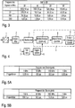
- a noise signal is superimposed on the measurement signal, which corresponds to a mean-free, white noise with the variance ⁇ n 2 , then there is no fixed trigger time t trigger as with a noise-free measurement signal, but according to FIG Fig. 1 jittering of the triggering time t trigger with a variance ⁇ t 2 that depends on the variance ⁇ n 2 of the noise signal.
- the trigger time t trigger of a noise-free measurement signal results from Fig. 1 and the derived therefrom trigger equation (1) with a trigger threshold u T of 1/2 and a slope steepness m of the measurement signal, a fixed value according to equation (2).
- a jittering trigger time t trigger results from a trigger threshold value u T of 1/2 and a slope steepness m of the measurement signal with a Mean of 1 2 ⁇ m and a variance ⁇ t 2 according to equation (5).
- the variance ⁇ t 2 of the jitter of the triggering time increases in the case of a measurement signal superimposed with a noise signal with an increasingly shallower rise m of the measurement signal. While in a high-frequency measurement signal with a high edge steepness m, the variance ⁇ t 2 of the jitter of the trigger point in accordance with Fig. 2A is comparatively low, the variance ⁇ t 2 of the jitter of the triggering time point is in accordance with a low-frequency measurement signal with a low edge steepness m Fig. 2B significantly higher and no longer negligible.
- a disadvantage of such a realization is the comparatively high circuit complexity (detection of the zero crossing, generation of the breakover voltage, initialization of the breakover voltage and detection of the setpoint passage).
- the object of the invention is therefore to develop a method and a device for digital triggering, with which the trigger inaccuracy is minimized with little effort in a measurement signal superimposed with a noise signal, in particular in the case of a low-frequency measurement signal.
- the object is achieved by a device for digital triggering with the features of claim 1 and by a method for digital triggering with the features of claim 2.
- the digital triggering is preceded by a low-pass filtering, which reduces the bandwidth of the measuring signal superimposed with a noise signal.
- the variance ⁇ n 2 of the noise signal is reduced, which leads to a minimization of the trigger error.
- the inventive device for digital triggering is in Fig. 4 and will be described below.
- the analog measurement signal with superimposed noise is converted in an analog / digital converter 1 into its corresponding digital data format.
- an equalization filter 2 an equalization of the linear or non-linearly distorted digitized measurement signal takes place.
- the signal at the output of the equalization filter 2 is compressed in a decimation unit 3 by passing only every n-th sample of the signal at the output of the equalization filter 2 to the recording unit 4.
- the signal at the output of the equalization filter 2 is supplied to a low-pass filter 5.
- the low-pass filter 5 in particular the higher-frequency noise signal compared with the measuring signal is band-limited according to the invention. In this way, the variance ⁇ n 2 of the noise signal is reduced.
- the band-limited measurement signal is compared with superimposed noise signal with adjustable threshold values for generating a trigger signal.
- the digital trigger signal is supplied to a recording controller 7 within the recording unit 4.
- the recording controller 7 the z. B. in an in Fig. 4 not shown ring buffer cyclically cached decimated samples of the superimposed with a noise signal measurement signal with respect to the trigger signal for the recording selected.
- the selected by the recording controller 7 samples of the superimposed with a noise signal measurement signal are stored in a subsequent acquisition memory 8 of the recording unit 4 and then on a visualization unit 9 z. B. a display, the recording unit 4 shown.
- the trigger errors of a device for digital triggering according to the prior art without low-pass filter for different frequencies of the measurement signal are listed in the table of Fig. 5B contain the trigger error of the inventive device for digital triggering for different frequencies of the measurement signal.
- the trigger error in a digital triggering device according to the invention significantly reduces over a large frequency range of the measurement signal compared to a device for digital triggering according to the prior art.
- the inventive method for digital triggering is in Fig. 6 shown.
- a first method step S10 the analog measurement signal superposed with a noise signal is converted in an analog-to-digital converter 1 into its corresponding digital data format.
- step S20 an equalization of the u.U. linear or non-linearly distorted digitized measurement signal superimposed with a noise signal.
- step S30 the digitized, equalized measurement signal superimposed with a noise signal is filtered in a low-pass filter.
- the method step S40 includes the generation of the trigger signal by threshold value comparison of the low-pass filtered, equalized, digitized measurement signal superimposed with a noise signal with a predetermined threshold value in a digital trigger unit.
- the rectified digitized measurement signal superimposed with a noise signal is compressed in the following method step S50 in a decimation unit by processing only every nth sample of the equalized digitized measurement signal superimposed with a noise signal.
- step S60 the recording of the compressed, equalized, digitized and superimposed with a noise signal measurement signal in response to the digital trigger signal.
- the invention is not limited to the illustrated embodiment. In particular, instead of a low-pass filtering, band-pass filtering with a bandwidth reducing the measuring signal superimposed with a noise signal can also be used.
Landscapes
- Physics & Mathematics (AREA)
- General Physics & Mathematics (AREA)
- Analogue/Digital Conversion (AREA)
- Compression, Expansion, Code Conversion, And Decoders (AREA)
- Measurement Of Mechanical Vibrations Or Ultrasonic Waves (AREA)
- Signal Processing Not Specific To The Method Of Recording And Reproducing (AREA)
Claims (2)
- Dispositif de déclenchement numérique d'un enregistrement d'un signal de mesure numérisé à signal de bruit superposé, comprenant une unité d'enregistrement numérique (4) et une unité de déclenchement numérique (6) déclenchant l'enregistrement du signal de mesure dans l'unité d'enregistrement (4) et à laquelle le signal de mesure est amené dans chaque cas, et un filtre passe-bas (5) monté en amont de l'unité de déclenchement numérique (6) pour limiter en largeur de bande le signal de bruit superposé sur le signal de mesure,
caractérisé en ce que
la largeur de bande du filtre passe-bas (5) est réglée en fonction de la pente du signal de mesure, afin de réduire la variance σt 2 de la guigue du signal de déclenchement numérique. - Procédé de déclenchement numérique d'un enregistrement numérique d'un signal de mesure numérisé à signal de bruit superposé, selon lequel un signal de déclenchement numérique est produit à partir du signal de mesure numérisé pour le déclenchement numérique de l'enregistrement numérique du signal de mesure et, avant la production du signal de mesure numérique, le signal de bruit superposé sur le signal de mesure numérisé est limité en largeur de bande par un filtrage passe-bas,
caractérisé en ce que
la largeur de bande du filtrage passe-bas est réglée en fonction de la pente du signal de mesure, afin de réduire la variance σt 2 de la guigue du signal de déclenchement numérique.
Applications Claiming Priority (2)
| Application Number | Priority Date | Filing Date | Title |
|---|---|---|---|
| DE102006021075A DE102006021075A1 (de) | 2006-05-05 | 2006-05-05 | Verfahren und Vorrichtung zur digitalen Triggerung eines mit einem Rauschsignal überlagerten Messsignals |
| PCT/EP2007/003453 WO2007128392A2 (fr) | 2006-05-05 | 2007-04-19 | Procédé et dispositif de déclencement numérique d'un signal de mesure à signal de bruit superposé |
Publications (2)
| Publication Number | Publication Date |
|---|---|
| EP2016428A2 EP2016428A2 (fr) | 2009-01-21 |
| EP2016428B1 true EP2016428B1 (fr) | 2017-11-01 |
Family
ID=38564907
Family Applications (1)
| Application Number | Title | Priority Date | Filing Date |
|---|---|---|---|
| EP07724390.5A Active EP2016428B1 (fr) | 2006-05-05 | 2007-04-19 | Procédé et dispositif de déclencement numérique d'un signal de mesure à signal de bruit superposé |
Country Status (4)
| Country | Link |
|---|---|
| US (1) | US8487607B2 (fr) |
| EP (1) | EP2016428B1 (fr) |
| DE (1) | DE102006021075A1 (fr) |
| WO (1) | WO2007128392A2 (fr) |
Cited By (1)
| Publication number | Priority date | Publication date | Assignee | Title |
|---|---|---|---|---|
| US11442089B2 (en) | 2019-10-09 | 2022-09-13 | Rohde & Schwarz Gmbh & Co. Kg | Apparatus and method for determining a trigger time |
Families Citing this family (7)
| Publication number | Priority date | Publication date | Assignee | Title |
|---|---|---|---|---|
| DE102006021075A1 (de) | 2006-05-05 | 2007-11-08 | Rohde & Schwarz Gmbh & Co. Kg | Verfahren und Vorrichtung zur digitalen Triggerung eines mit einem Rauschsignal überlagerten Messsignals |
| CN104422804B (zh) * | 2013-08-21 | 2018-07-13 | 苏州普源精电科技有限公司 | 一种具有噪声抑制功能的混合示波器 |
| JP6370667B2 (ja) * | 2014-10-15 | 2018-08-08 | 日置電機株式会社 | 波形表示装置 |
| CN110231505B (zh) * | 2019-06-06 | 2020-12-08 | 西安交通大学 | 一种基于三次样条插值的示波器波形抖动修正方法 |
| JP7774977B2 (ja) * | 2021-05-11 | 2025-11-25 | 株式会社アドバンテスト | 測定装置および測定方法 |
| DE102021130772A1 (de) | 2021-11-24 | 2023-05-25 | H-Next Gmbh | Verfahren und Vorrichtung zur Signal-Mustererkennung |
| CN115290125B (zh) * | 2022-10-10 | 2023-02-10 | 泉州昆泰芯微电子科技有限公司 | 注入随机噪声进行信号修调的方法及磁性编码器 |
Family Cites Families (10)
| Publication number | Priority date | Publication date | Assignee | Title |
|---|---|---|---|---|
| US4209843A (en) * | 1975-02-14 | 1980-06-24 | Hyatt Gilbert P | Method and apparatus for signal enhancement with improved digital filtering |
| US3704416A (en) * | 1970-07-13 | 1972-11-28 | Ibm | Sequential sampling system |
| US4553221A (en) * | 1970-12-28 | 1985-11-12 | Hyatt Gilbert P | Digital filtering system |
| US5053983A (en) * | 1971-04-19 | 1991-10-01 | Hyatt Gilbert P | Filter system having an adaptive control for updating filter samples |
| DE3418500C2 (de) | 1984-05-18 | 1986-06-26 | Deutsche Forschungs- und Versuchsanstalt für Luft- und Raumfahrt e.V., 5000 Köln | Verfahren und Vorrichtung zur Triggerung von elektrischen Signalen |
| US5272439A (en) * | 1992-02-21 | 1993-12-21 | University Of Connecticut | Method and apparatus for the detection and location of faults and partial discharges in shielded cables |
| JPH07234250A (ja) | 1994-02-25 | 1995-09-05 | Yokogawa Electric Corp | トリガ装置 |
| US6812688B2 (en) * | 2001-12-12 | 2004-11-02 | Tektronix, Inc. | Signal acquisition method and apparatus using integrated phase locked loop |
| US7072804B2 (en) * | 2004-09-28 | 2006-07-04 | Agilent Technologies, Inc. | Digital trigger filter for a real time digital oscilloscope |
| DE102006021075A1 (de) | 2006-05-05 | 2007-11-08 | Rohde & Schwarz Gmbh & Co. Kg | Verfahren und Vorrichtung zur digitalen Triggerung eines mit einem Rauschsignal überlagerten Messsignals |
-
2006
- 2006-05-05 DE DE102006021075A patent/DE102006021075A1/de not_active Withdrawn
-
2007
- 2007-04-19 US US12/299,751 patent/US8487607B2/en active Active
- 2007-04-19 EP EP07724390.5A patent/EP2016428B1/fr active Active
- 2007-04-19 WO PCT/EP2007/003453 patent/WO2007128392A2/fr not_active Ceased
Non-Patent Citations (2)
| Title |
|---|
| DESROCHERS E: "LOWPASS FILTER DISCRIMINATES STEP INPUT FROM NOISE", EDN ELECTRICAL DESIGN NEWS.(TEXAS INSTRUMENT), REED BUSINESS INFORMATION, HIGHLANDS RANCH, CO, US, vol. 48, no. 20, 18 September 2003 (2003-09-18), pages 92,96, XP001177659, ISSN: 0012-7515 * |
| JUNGERMAN R L ET AL: "Switched-radar scenarion generation with Femtosecond jitter", INTERNET CITATION, August 2005 (2005-08-01), XP002461834, Retrieved from the Internet <URL:http://rfdesign.com/mag/508RFDSF2.pdf> [retrieved on 20071211] * |
Cited By (1)
| Publication number | Priority date | Publication date | Assignee | Title |
|---|---|---|---|---|
| US11442089B2 (en) | 2019-10-09 | 2022-09-13 | Rohde & Schwarz Gmbh & Co. Kg | Apparatus and method for determining a trigger time |
Also Published As
| Publication number | Publication date |
|---|---|
| US8487607B2 (en) | 2013-07-16 |
| DE102006021075A1 (de) | 2007-11-08 |
| WO2007128392A3 (fr) | 2008-02-28 |
| US20100045260A1 (en) | 2010-02-25 |
| EP2016428A2 (fr) | 2009-01-21 |
| WO2007128392A2 (fr) | 2007-11-15 |
Similar Documents
| Publication | Publication Date | Title |
|---|---|---|
| EP2016428B1 (fr) | Procédé et dispositif de déclencement numérique d'un signal de mesure à signal de bruit superposé | |
| DE102013200941A1 (de) | Verfahren und Vorrichtung zur Bestimmung einer Triggerbedingung für ein seltenes Signalereignis | |
| WO2012152818A1 (fr) | Analyse de signaux en temps et fréquence | |
| EP1409965A1 (fr) | Procede et dispositif de correction de l'erreur dynamique d'un detecteur | |
| EP1391029A1 (fr) | Procede pour determiner la position angulaire de l'arbre d'entrainement d'un moteur a courant continu a commutation | |
| EP2850395B1 (fr) | Procédé de déparasitage d'un processus d'échantillonnage ainsi que dispositif pour exécuter ledit procédé | |
| DE3750001T2 (de) | Verfahren und Gerät zum Verarbeiten aufgezeichneter, wellenförmiger Signale. | |
| EP1794602B1 (fr) | Procédé et dispositif d'analyse spectrale d'un signal utile ou d'un signal de bruit | |
| DE10255687B4 (de) | Verfahren zur Verringerung des Crestfaktors eines Multiträgersignals | |
| DE3917309A1 (de) | Verfahren und einrichtung zum reduzieren von durch verstuemmelung verursachten artefakten | |
| DE602005005396T2 (de) | Filter zur Eliminierung der Überschwingungen | |
| DE19757296A1 (de) | Verfahren zum Bestimmen und Kompensieren der Übertragungsfunktion eines Meßgerätes, insbesondere eines Spektrum-Analysators | |
| DE3112243C2 (de) | Klirrfaktormeßgerät | |
| EP1592131A1 (fr) | Analyseur de spectre présentant simultanément une vitesse élevée et une haute résolution | |
| DE102008060385B4 (de) | Verfahren und Vorrichtung für eine zeitoptimierte Ermittlung des Frequenzganges von in einem Messobjekt erzeugten Harmonischen | |
| EP0777130A2 (fr) | Procédé digital de détection d'impulsions courtes et appareil pour la mise en oeuvre du procédé | |
| DE102006052842A1 (de) | Jittermessvorrichtung, Jittermessverfahren und Prüfvorrichtung | |
| DE102012208261A1 (de) | Verfahren zur Entstörung eines Abtastprozesses sowie eine Vorrichtung zur Durchführung des Verfahrens | |
| DE10242333A1 (de) | Verfahren zum Bestimmen der Hüllkurve eines modulierten Signals | |
| EP1436960B1 (fr) | Procede pour mesurer l'erreur de modulation de signaux de haute frequence modules par voie numerique | |
| DE102012208405A1 (de) | Messgerät und Verfahren zur verbesserten Abbildung von Spektralverläufen | |
| DE102010046098A1 (de) | Messvorrichtung mit einer Triggereinheit | |
| DE3309717C2 (fr) | ||
| EP3607693B1 (fr) | Procédé d'établissement d'une valeur numérique à partir d'un signal d'horloge et d'un signal de données | |
| DE102005036855B4 (de) | Verfahren und System zur Triggerung von digitalisierten Signalen |
Legal Events
| Date | Code | Title | Description |
|---|---|---|---|
| PUAI | Public reference made under article 153(3) epc to a published international application that has entered the european phase |
Free format text: ORIGINAL CODE: 0009012 |
|
| 17P | Request for examination filed |
Effective date: 20080910 |
|
| AK | Designated contracting states |
Kind code of ref document: A2 Designated state(s): AT BE BG CH CY CZ DE DK EE ES FI FR GB GR HU IE IS IT LI LT LU LV MC MT NL PL PT RO SE SI SK TR |
|
| AX | Request for extension of the european patent |
Extension state: AL BA HR MK RS |
|
| DAX | Request for extension of the european patent (deleted) | ||
| RBV | Designated contracting states (corrected) |
Designated state(s): DE FR GB |
|
| 17Q | First examination report despatched |
Effective date: 20161128 |
|
| REG | Reference to a national code |
Ref country code: DE Ref legal event code: R079 Ref document number: 502007015932 Country of ref document: DE Free format text: PREVIOUS MAIN CLASS: G01R0013020000 Ipc: G01D0003032000 |
|
| GRAP | Despatch of communication of intention to grant a patent |
Free format text: ORIGINAL CODE: EPIDOSNIGR1 |
|
| RIC1 | Information provided on ipc code assigned before grant |
Ipc: G01R 13/02 20060101ALI20170628BHEP Ipc: G01D 3/032 20060101AFI20170628BHEP |
|
| INTG | Intention to grant announced |
Effective date: 20170711 |
|
| GRAS | Grant fee paid |
Free format text: ORIGINAL CODE: EPIDOSNIGR3 |
|
| GRAA | (expected) grant |
Free format text: ORIGINAL CODE: 0009210 |
|
| AK | Designated contracting states |
Kind code of ref document: B1 Designated state(s): DE FR GB |
|
| REG | Reference to a national code |
Ref country code: GB Ref legal event code: FG4D Free format text: NOT ENGLISH |
|
| REG | Reference to a national code |
Ref country code: DE Ref legal event code: R096 Ref document number: 502007015932 Country of ref document: DE |
|
| REG | Reference to a national code |
Ref country code: FR Ref legal event code: PLFP Year of fee payment: 12 |
|
| REG | Reference to a national code |
Ref country code: DE Ref legal event code: R097 Ref document number: 502007015932 Country of ref document: DE |
|
| PLBE | No opposition filed within time limit |
Free format text: ORIGINAL CODE: 0009261 |
|
| STAA | Information on the status of an ep patent application or granted ep patent |
Free format text: STATUS: NO OPPOSITION FILED WITHIN TIME LIMIT |
|
| 26N | No opposition filed |
Effective date: 20180802 |
|
| P01 | Opt-out of the competence of the unified patent court (upc) registered |
Effective date: 20230525 |
|
| PGFP | Annual fee paid to national office [announced via postgrant information from national office to epo] |
Ref country code: DE Payment date: 20250417 Year of fee payment: 19 |
|
| PGFP | Annual fee paid to national office [announced via postgrant information from national office to epo] |
Ref country code: FR Payment date: 20250422 Year of fee payment: 19 |
|
| PGFP | Annual fee paid to national office [announced via postgrant information from national office to epo] |
Ref country code: GB Payment date: 20260324 Year of fee payment: 20 |