EP2016567B1 - Consigneur - Google Patents
Consigneur Download PDFInfo
- Publication number
- EP2016567B1 EP2016567B1 EP07724617A EP07724617A EP2016567B1 EP 2016567 B1 EP2016567 B1 EP 2016567B1 EP 07724617 A EP07724617 A EP 07724617A EP 07724617 A EP07724617 A EP 07724617A EP 2016567 B1 EP2016567 B1 EP 2016567B1
- Authority
- EP
- European Patent Office
- Prior art keywords
- deposit
- lock
- cam
- checking
- slot
- Prior art date
- Legal status (The legal status is an assumption and is not a legal conclusion. Google has not performed a legal analysis and makes no representation as to the accuracy of the status listed.)
- Active
Links
Images


Classifications
-
- G—PHYSICS
- G07—CHECKING-DEVICES
- G07F—COIN-FREED OR LIKE APPARATUS
- G07F7/00—Mechanisms actuated by objects other than coins to free or to actuate vending, hiring, coin or paper currency dispensing or refunding apparatus
- G07F7/06—Mechanisms actuated by objects other than coins to free or to actuate vending, hiring, coin or paper currency dispensing or refunding apparatus by returnable containers, i.e. reverse vending systems in which a user is rewarded for returning a container that serves as a token of value, e.g. bottles
- G07F7/0618—Mechanisms actuated by objects other than coins to free or to actuate vending, hiring, coin or paper currency dispensing or refunding apparatus by returnable containers, i.e. reverse vending systems in which a user is rewarded for returning a container that serves as a token of value, e.g. bottles by carts
- G07F7/0654—Mechanisms actuated by objects other than coins to free or to actuate vending, hiring, coin or paper currency dispensing or refunding apparatus by returnable containers, i.e. reverse vending systems in which a user is rewarded for returning a container that serves as a token of value, e.g. bottles by carts in which the lock functions according to a "pinching of the token" principle, i.e. the token is held between two members
Definitions
- the invention relates to a deposit lock and a method for testing a deposit with the features in the preamble of the method and device main claim.
- Deposit locks in various embodiments are known from practice.
- the deposit locks together with a coupling element form a deposit system and serve to secure shopping carts or the like.
- Such deposit systems aim to ensure that the customer brings his shopping cart back to the collection point and the Carbox in commercial transactions. This should be achieved through a deposit, which must be inserted into the deposit lock to unlock the lock part and remove the car can. When returning the car, the deposit lock is locked again by inserting a coupling element and the deposit is issued.
- Such deposit locks should be tamper-proof and be able to check the pledge, usually a coin, as accurately as possible on its authenticity.
- the prior art systems are not sufficiently accurate in the deposit test and not tamper-proof.
- the invention solves this problem with the features in the method and device main claim.
- the claimed deposit test has the advantage of providing greater inspection accuracy and tamper resistance than the prior art.
- the accuracy of the test can be increased if there is a translation between deposit scanning and rotary tester, because even very small size differences lead to a significant reaction of the rotary tester.
- the rotary tester which ultimately decides on the release or blocking of the trigger of the lock part, is hidden inside the locker and can not be accessed and manipulated externally with tools. Also, the rotary tester can not be outsmarted by raising the deposit scan with a tool because the release of the rotary tester occurs in an intermediate scan position that can not be met in a tampering attempt.
- the deposit lock has the advantage that it can be adjusted in a simple and cost-effective manner to a variety of deposit sizes. For this purpose, only a few parts, especially the rotary tester, the receiving slot and the deposit plunger to adjust. The other components of the deposit lock can remain the same. Due to the identical parts a very cost-effective production of the deposit lock is possible.
- the deposit lock allows on the one hand the aforementioned exact coin check. If only one specific deposit size is specified, extreme test accuracy can be achieved. On the other hand, the deposit lock offers the possibility of operating with several differently sized pawns or coins, whereby a high füraugtechnik can be achieved despite the deposit differences. As a result, the deposit lock has a very wide range of applications, whereby a wide variety of customer needs can be met with minimal effort.
- the operation with several different sized pledges or coins can be done in conjunction with a single receiving slot (deposit area) or several possibly parallel receiving slots (deposit selection).
- the range of permissible pledges or deposit sizes can be spread as far as possible in both variants and changed in a simple and cost-effective manner if necessary, as well as to different conditions of use, e.g. adjust different coin sizes in different countries. Even retrofits or conversions are possible at the deposit lock in the various design and function variants (individual deposit, pledge area and deposit selection) in a simple and cost-effective manner.
- the deposit lock can also be equipped with a very effective deposit barrier, which prevents unauthorized deposit collection.
- a lever ratio and a translation can be effective and implement small actuating movements in large blocking movements.
- the hidden accommodation of the deposit check in the case of the deposit lock is also favorable.
- the deposit check area is only accessible from the outside through narrow slits, which can also be adapted to the deposit size and provide a rough preselection of the deposit size.
- the deposit lock also has the advantage that the deposit can be pushed very deep into the slot and from the outside is very difficult to reach. When unlocking the deposit lock, it is safely ejected again by the forced guides.
- the recoverable backlash of the movable pawn lock parts are also favorable.
- the invention relates to a deposit lock (2) and a method for testing Pf skilled (11).
- the invention also deals with a deposit system (1), which consists of one or more deposit locks (2) and one or more coupling parts (3).
- the invention also relates to a cart, in particular a shopping cart or luggage cart, which is equipped with such a deposit system (1) or a deposit lock (2) and a coupling part (3).
- the car is not shown for clarity.
- a replacement part (15) of a shopping cart, such as a handle spar, is shown in cross-section as a substitute.
- the deposit lock (2) is operated with one or more Pf suitable (11), which may be of any type, shape and / or size. These can be, for example, coins that can have different values and different sizes.
- Pf suitable (11) can be, for example, coins that can have different values and different sizes.
- the deposit lock (1) can be operated with a single deposit (11) or a coin.
- FIGS. 2 to 6 clarify the training provided for this in detail. Alternatively, it is possible to use several different sized Pf section (11) or coins.
- the relevant embodiment of the deposit lock (2) is in the FIGS. 7 to 12 shown and described.
- the pledgets (11) are coins of the usual circular shape.
- the pledgets (11) may have a prismatic shape or any other shape.
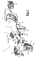
- FIG. 1 the components of a deposit lock (2) are shown in an exploded view.
- the deposit lock (2) comprises a lock part (4), a deposit (5), a deposit check (6) and a trigger (7) for releasing or blocking a coupling part (3), which in FIG. 1 the clarity omitted and in the drawings in FIGS. 2 to 12 is shown.
- the deposit lock (2) has a housing (12) in which the aforementioned components are housed.
- the housing (12) can be multi-part. It can e.g. a main housing, in which a plurality of guide elements for the lock part (4) are housed. Further, in the housing (12), a left and right mechanism carrier (26,27) are introduced. The parallel and shield-like formed mechanical support (26,27) have guide elements (31,34,52) for the recorded between them parts of the deposit test (6). In addition, components of the lock part (4) can be mounted and guided on the mechanical carriers (26, 27).
- the Pfandability (5) has its own housing (22), which can be coupled to the main housing (12) via a corresponding receptacle and also with the mechanics carriers (26,27) can be connected.
- the deposit lock (2) can be arranged on a carriage or any other type of carrier in any suitable manner.
- FIG. 2 shows a possible embodiment with the attachment to the handle rail (15) of a shopping cart.
- the deposit lock (2) can for this purpose have an adapter (14), which is for example mounted longitudinally adjustable on the underside of the housing (12) and can be adjusted to the handle spar (15) with a suitable clamping mechanism.
- the housing (12) has a corresponding cup-shaped Holmsuit on the underside, wherein the handle spar (15) between the spar holder and the adapter (14) can be clamped and fixed.
- any other attachment mechanisms are possible.
- the coupling part (3) can also be fastened to the shopping cart, eg at the deposit lock (2), with a short chain or the like.
- the coupling part (3) can be formed in any desired manner, for example as a flatter Socket, which can be inserted through insertion slot (13) on the housing front (12) and with the lock part (4) of the deposit lock (2) cooperates.
- the lock part (4) has a locking mechanism (19), which can be of any desired design and is actuated by a trigger (7). Its operation in turn depends on the deposit test (6).
- the locking mechanism (19) has e.g. at least one blocking element (20), for example a movably mounted blocking ball, which can engage in a blocking engagement with a receiving opening on the tongue of the coupling part (3). This engagement position can be secured by a lock (21), which can also be of any kind and which also disables manipulation of the lock part (4) by a tool inserted into the insertion slot (13).
- the spring-loaded latch (21) can be multi-level.
- the trigger (7) comprises a deposit slide (17), which is eg mounted translationally movable on the mechanism carriers (26, 27) and in a housing insert (16) and has a displacement direction parallel to the insertion direction (53) of the deposit (11). is aligned.
- the deposit slide (17) is actuated and moved by a deposit plunger (47) via a driver (45), whereby the slide movement can be blocked or released via the deposit check (6).
- the deposit slide (17) actuates the locking mechanism (19) and presses, for example, the blocking ball (20) in the receptacle on the coupling part (3).
- the lock (21) also acts on the deposit slide (17) and blocks its displacement movement, which can only be solved when inserting a correct deposit (11) in the deposit lock (2). In this case, the locking mechanism (19) is unlocked and released the coupling part (3) for removal.
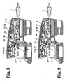
- the deposit check (6) has a deposit scan (9) for detecting the deposit size.
- the deposit scan (9) is e.g. essentially linearly movable. Alternatively, other movements, e.g. Pivoting movements possible.
- a rotary tester (10) is coupled, which is connected to the trigger (7).
- the rotary tester (10) can perform a pivoting movement and thereby assume different rotational positions, which are dependent on the deposit size and the movement of the deposit scanning (9).
- With the correct deposit size of the rotary tester (10) assumes a predetermined rotational position, in which he releases the trigger (7). In the embodiment shown, in this release position, the deposit slide (17) can be advanced by the deposit plunger (47) and the lock mechanism (19) can be unlocked.
- the rotary tester (10) locks the trigger (7).
- the implementation of the preferably linear movement of the deposit scanning (9) in the pivoting movement of the rotary tester (10) can be done with a gear ratio.
- the gear ratio can be chosen arbitrarily. Preferably, it is about 2: 1 or greater, e.g. 2.5: 1.
- One millimeter of linear movement of the deposit scan (9) is hereby translated into 2 mm or 2.5 mm pivot travel or arc path of the rotary tester (10).
- the rotary tester (10) releases the displacement movement of the deposit slide (17) as a function of its rotational position or blocks it.
- the rotary tester (10) may be formed in any suitable manner.
- the rotary tester (10) has a cam-slot arrangement (39). This has a test cam (40) and a cam receiver (44) with a test slot (42), wherein the cam receiver (44) and the fürnocke (40) are movable relative to each other. This is preferably a mutual relative rotation.
- the test cam (40) and the Test slit (42) are mutually adapted in size such that in a correct position (11) occupied passport position the test cam (40) can pass through the test slot (42).
- the cam receptacle (44) with the test slot (42) is arranged on the deposit slide (17), the test cam (40) being located on a deposit inquiry (32) explained below.
- the assignment and the kinematics can be reversed in an alternative embodiment.
- the deposit scan (9) is made according to FIG. 2 and 3 of a substantially linearly movable deposit jaw (28) with a touch plate (29), which is aligned substantially parallel to the insertion direction (53) of the deposit (11).
- the Pfandabtastung (9) is located inside the deposit (5) and is operated by the pledge (11).
- the Pfandage (5) has a housing (22) with at least one insertion opening for the pledge (11).
- the insertion opening is designed as a receiving slot (23), which is preferably arranged in a vertical position, for direct insertion of the deposit (11). It can also several, for example, two receiving slots (23) are arranged closely adjacent to each other. Alternatively, the insertion can be designed or arranged differently.
- a deposit introduction with a carrier for example a spring-loaded carriage, is possible.
- the dimensions of the receiving slot (23) and in particular the slot opening formed by solid walls are adapted to the intended deposit size and provide a rough preselection of the permissible deposit sizes and size limit upwards.
- the receiving slot (s) (23) have a preferably flat and substantially horizontally oriented bottom and a back and preferably substantially vertical end wall (25). In the receiving slot (23) protrude the touch plate (29) and the deposit plunger (47).
- the touch plate (29) is preferably arranged parallel to the bottom (24) and on its opposite side.
- the touch plate (29) extends for example about half the slot depth and is so long that it is permanently connected to the top of the imported deposit (11).
- the touch plate (29) may extend transversely across a plurality of parallel receiving slots (23). It is guided vertically adjustable transversely to its main plane in the housing (12) by means of a guide (31).
- the guide (31) can also be aligned obliquely to the plate plane.
- the touch panel (29) may have a groove on the underside.
- the deposit jaw (28) has two laterally attached to the touch plate (29) side arms (30) which engage with the guide (31) arranged on both sides.
- the deposit jaw (28) can be moved upwards by the deposit (11) against a restoring force.
- the restoring force can be formed, for example, by a spring, not shown in the drawings, which engage on one or both side arms (30) and can be arranged in the slot-like guide (31).
- FIG. 1 shows on the right side arm (30), for example, a receiving pin for attaching the spring.
- the touch plate (29) has a flat top and is here connected to a pivotable deposit inquiry (32) of the rotary tester (10).
- the deposit inquiry (32) is for example designed as a curved pivot lever (33) which is rotatably mounted in a housing-fixed pivoting guide (34).
- the pivot lever (33) has a first or front lever arm (37) which is directed to the touch plate (29) and here abuts with a rounded end of the lever.
- the pivot lever (33) further has a second or rear lever arm (38) on which the test cam (40) is arranged.
- the at least within the pivot guide (34) circular arc-shaped curved pivot lever (33) has a center of curvature, which represents the axis of rotation of the pivoting movements.
- the lever arms (37, 38) have a different length.
- the first or front lever arm (37) is shorter than the second or rear lever arm (38), forming a gear ratio.
- the distances between the test cam (40) arranged at the rear end of the second lever arm (38) and the front end of the first lever arm (37) with respect to the axis of rotation determine the transmission ratio, for example a size of approximately 2: 1 or more, eg 2.5 : 1 has.
- the deposit inquiry (32) and the pivot lever (33) also move against a restoring force, e.g. is formed by a spring (36) which cooperates with a subsequently explained in more detail deposit lock (8) and the locking arm (49).
- a spring (36) which cooperates with a subsequently explained in more detail deposit lock (8) and the locking arm (49).
- the spring (36) can also be supported elsewhere and in a stationary manner.
- the deposit lock (2) allows a deposit check in which the pledge size or deposit form is scanned very accurately and leads to a corresponding rotational position of the rotary tester (10). The accuracy can be increased by the aforementioned leverage. Small size or diameter deviations of the deposit (11) already lead to larger pivoting movements of the turnstile (10). FIGS. 2 to 6 clarify such an arrangement explained in more detail below.
- the deposit lock (2) may be tuned to an operation specifying a single particular type of deposit (11) or a single particular shape or size of a deposit (11). This is referred to below as single deposit control. Furthermore, an operation with various allowable deposit sizes and in particular coin diameters is possible.
- FIGS. 7 to 12 show this deposit lock variant, where in FIG. 7 the size deviation d of the pledges (11) is shown.
- two or more possibly parallel and adapted to the different deposit sizes receiving slots (23) may be present, which is referred to as a deposit selection or coin selection.
- This variant is called deposit area or coin area. In both variants, an exact deposit check can be carried out for each deposit size.
- FIG. 3 shows the deposit check (6) with the deposit scan (9) and the rotary tester (10) in an enlarged view.
- the test cam (40) is shown by the second lever arm (38).
- FIG. 1 shows the whole geometry.
- a cam receptacle (44) is arranged in the aforementioned manner, which is formed here as upwardly standing and concentric with the axis of rotation of the pivot lever (33) curved groove guide.
- the test cam (40) dives into the groove from the side and can pivot upwards and downwards in the groove in a circular arc movement.
- the wall of the cam receiver (44) has said test slot (42). This is eg horizontal or arranged parallel to the insertion direction (53).
- the slot direction is also aligned with the direction of movement of the deposit slide (17).
- the side walls of the guide slot (42) are aligned parallel and along the direction of displacement.
- the test cam (40) also has parallel side walls.
- test slot (42) is slightly larger than the width of the excnocke (40), so that in the fitting position, the cam and slot walls are aligned parallel and the pawn slide (17) in the direction of displacement to the coupling part (3) can be moved, the test slot (42) slides over the fixedly held cam (40).
- the width of the test slot (42) is smaller than the arc length of the groove in the cam receiver (44).
- the test slot (42) is also not at the groove end, but is a distance therefrom and lies in a range between the end positions of the relative movement path between excnocke (40) and cam receiver (44).
- FIG. 3 further illustrates a safety catch (41) on the fürnocke (40) and the test slot (42).
- the sketchnocke (44) at the slot end has a catch opening, which is formed by two arms or catch wedges (43) with funnel-like bevelled front walls.
- the walls of the cam receiver (44) also have beveled and tapered wall sections at the ends of the test slot (42) which form corresponding oblique catch wedges (43). Only when the test cam (40) in the direction of displacement is aligned exactly opposite the test slot (42), it can dive into the test slot (42) with a slider movement. If there is a misalignment, which can be very small, the catch wedges (43) on one side engage each other and get stuck by their inclination. The wedge effect enhances this entanglement effect, which brings the test cam (40) and the cam receptacle (44) in a blocking position and prevents a sliding movement of the deposit slide (17).
- FIG. 4 shows the situation with a single deposit control and with inserted coupling part (3) in a first operating step, in which a suitable deposit (11) is inserted into the receiving slot (23).
- a suitable deposit (11) is inserted into the receiving slot (23).
- the possibly on the floor (24) rolling pawn (11) pushes the touch plate (29) upwards.
- the restoring spring force of the touch plate (29) maintains the contact at the zenith of the coin circumference.
- the lifting movement of the touch plate (29) is converted into a rotational movement of the pivot lever (33) against the force of its spring (36), wherein in the case of a correct deposit (11) the strignocke (40) in alignment before the opening of the strigschlitzes (42) lie comes.
- FIG. 5 illustrates the following step, wherein the pledge (11) is pushed even deeper into the receiving slot (23) while pressing against the deposit plunger (47).
- the pledge (47) is according to FIG. 3 and 4 in a housing-fixed ram guide (48) movably mounted in the direction of movement of the deposit slide (17) and engages this via a driver (45) in a driving connection or thrust connection.
- the length of the deposit plunger (47) and its immersion depth in the receiving slot (23) are adapted to the correct deposit size.
- FIG. 4 and 5 show this process.
- FIG. 3 illustrates, it has a pivotable locking arm (49) having at its rear end adapted to the deposit size locking lug (51), which dive from above into the receiving slot (23) and engage behind the pledge (11) in the end position can.
- the pledge (11) is so deeply immersed in the end position in the receiving slot (23) that only a small part of its rear edge protrudes.
- the locking arm (49) is disposed in close proximity to the pivoting lever (33) and bent concentrically to its axis of rotation.
- the blocking arm (49) lies, for example, on the outside on the pivoting lever (33) and is guided in its pivoting movement in a housing-fixed arm guide (52).
- the spring (36) is according to FIG. 3 and 4 clamped between the pivot lever (33) and the locking arm (49). It is designed as a compression spring and spreads the two arms in opposite directions.
- the locking arm (49) has a groove (50) in which the spring (36) is inserted. At the rear end, the groove is open at the bottom.
- a radially projecting stop (35) of the pivot lever (33) in the groove (50) and serves as a rear stop for the spring (36).
- FIG. 2 and 3 show this end position.
- the blocking arm (49) can rotate back under the action of the spring (36), as a result of which the locking nose (51) returns to the retracted position and releases the deposit (11), which is pushed out by the deposit plunger (47).
- the under the force of the spring (36) and its own (not shown) restoring spring touch plate (29) in this case prevents the deposit (11) out.
- test cam (40) assumes an end position at the upper end of the groove in the cam receptacle (44), in which it engages behind the groove wall and blocks a sliding movement of the deposit slide (17). Due to the various restoring forces and springs, in particular the spring (36), the system is free of play.
- FIGS. 7 to 12 clarify the case of the deposit selection or the deposit area with different-sized allowable deposit diameters.
- the deposit plunger (47) may be multi-armed and, for example, have two parallel key arms which have a different length adapted to the respective deposit size.
- FIG. 1 shows this training, which can be used in particular in the deposit selection. In the individual deposit check or in the deposit area, the deposit plunger (47) can be one-armed.
- test slot (42) has a larger width, which is also greater than the width of the scholarnocke (40).
- the test slot (42) is located in a central position at a distance from the slot ends or the cam end positions in order to protect against theft.
- the position of the side walls of the test slot (42) is matched to the limits of the different deposit sizes. Accordingly, the side walls of the test cam (40) are adapted to these limits, wherein in the two marginal rotational positions, the side walls are aligned in each case in alignment with the adjacent slot wall.
- the touch plate (29) For the deposit control in the variant of the deposit area with a receiving slot (23) for different deposit sizes, the touch plate (29) the same training as in the individual deposit test according to FIGS. 2 to 6 have, because of the diameter differences d of the stroke of the touch panel (29) and the guide (31) can be extended.
- a common and both receiving slots (23) overlapping touch plate (29) with possibly several Pfand Adjustsnuten be present.
- the touch plate (29) may have a substantially planar extension and a prolonged stroke similar to the deposit area.
- the touch plate (29) on the underside of a step shape to adapt to the different deposit diameters and a flat top for connection to the deposit inquiry (32).
- the step shape compensates for the diameter differences d.
- a compensation of the differences in diameter d by raising the bottom (24) in the smaller deposit (11) in conjunction with a flat touch plate (29) done, so that in both cases the formation and function of the deposit test (6) and the deposit lock the the same as in the above-described embodiment of the individual deposit test can be.
- FIG. 8 clarifies the situation in the deposit area and the deposit selection with a flat touch plate (29) and extended stroke in the introduction of the larger deposit, which raises the touch plate (29) far enough and the pivot lever (33) rotates so far that the scholarnocke (40), the lower limit position occupies.
- its lower side wall is aligned with the lower diaphragm wall and allows the in FIG. 10 advancing the deposit slide (17) shown in the second step.
- FIG. 9 clarifies the situation with the smaller pledge (11).
- the sketchnocke (40) which has a the deposit size difference d taking into account the translation correspondingly smaller width than the slot width, located in the limit position for the small pledge (11) in alignment at the upper end of the slot and allows the in FIG. 11 shown moving the deposit slide (17).
- the deposit lock (8) comes to the function.
- the rotary tester (10) affects the different deposit size only on the rotational position of the rotary tester (10), but has no effect on the displacement of the deposit slide (17).
- the deposit lock (8) is operated in the same way for both coin sizes.
- FIGS. 10 and 11 clarify this feature.
- FIG. 12 is the also in the deposit selection and the deposit area functioning Matterlistungs remedy shown. Due to the central position of the test slot (42), the associated center position of the touch plate (29) must also be found here without aids, which is practically impossible. If the touch plate (29) is pressed against the upper stop, also comes in this case the educanocke (40) in the lower end of the curved groove in abutment and the catch (41) in stop and Blockadegna for the pawn shifter (17).
Landscapes
- Physics & Mathematics (AREA)
- General Physics & Mathematics (AREA)
- Lock And Its Accessories (AREA)
- Financial Or Insurance-Related Operations Such As Payment And Settlement (AREA)
- Handcart (AREA)
- Control Of Vending Devices And Auxiliary Devices For Vending Devices (AREA)
- Fluid-Damping Devices (AREA)
- Fuel-Injection Apparatus (AREA)
- Rigid Pipes And Flexible Pipes (AREA)
- Consolidation Of Soil By Introduction Of Solidifying Substances Into Soil (AREA)
Claims (20)
- Serrure de consignation à jetons pour chariots à provisions ou objets similaires, conçue pour recevoir une pièce d'accouplement (3), ladite serrure de consignation (2) comprenant une partie de verrouillage (4), un receveur (5) de jetons, un système (6) de contrôle de jetons et un déclencheur (7) destiné à la libération ou au blocage de ladite pièce d'accouplement (3), ledit système (6) de contrôle de jetons comportant un système (9) palpeur de jetons, dédié à la détection de la taille desdits jetons, et un vérificateur rotatif (10) couplé audit système (9) palpeur de jetons, sachant que ledit vérificateur rotatif (10), relié audit déclencheur (7), libère ou bloque ledit déclencheur (7) en fonction de la position qu'il a prise par rotation, caractérisée par le fait que le vérificateur rotatif (10) possède un ensemble (39) à came et à fente, ledit ensemble (39) à came et à fente comprenant une came de contrôle (40) et un logement (44) de came, muni d'une fente de contrôle (42), qui sont doués de mobilité relative et dont les tailles sont réciproquement adaptées de façon telle que ladite came de contrôle (40) puisse franchir ladite fente de contrôle (42) dans une position ajustée, en présence d'une taille de jeton correcte.
- Serrure de consignation selon la revendication 1, caractérisée par le fait que le système (9) palpeur de jetons est, pour l'essentiel, mobile linéairement.
- Serrure de consignation selon la revendication 1 ou 2, caractérisée par le fait que le mouvement exploratoire du système (9) palpeur de jetons peut être converti en un mouvement pivotant du vérificateur rotatif (10).
- Serrure de consignation selon l'une des revendications précédentes, caractérisée par le fait que ladite serrure de consignation (2) présente un système (8) de blocage de jetons.
- Serrure de consignation selon la revendication 4, caractérisée par le fait que le système (8) de blocage de jetons offre un bras pivotant de blocage (49), pourvu d'un mentonnet de blocage (51) adapté à la taille desdits jetons.
- Serrure de consignation selon l'une des revendications précédentes, caractérisée par le fait que le système (9) palpeur de jetons comporte une mâchoire de consignation (28) douée, pour l'essentiel, de mobilité linéaire et associée à une platine exploratrice (29) orientée, pour l'essentiel, parallèlement à la direction d'introduction (53).
- Serrure de consignation selon la revendication 6, caractérisée par le fait que la mâchoire de consignation (28) est mobile en opposition à une force de rappel, notamment à un ressort (36), et un interrogateur (32) de jetons peut être actionné en opposition à une force de rappel, notamment à un ressort (36).
- Serrure de consignation selon l'une des revendications précédentes, caractérisée par le fait que la fente de contrôle (42) est disposée dans la région située entre les positions extrêmes de la trajectoire de mouvement relatif du logement (44) de came et de la came de contrôle (40).
- Serrure de consignation selon l'une des revendications précédentes, caractérisée par le fait que, pour couvrir l'étendue d'une plage de consignations, la fente de contrôle (42) offre une largeur plus grande que la largeur de la came de contrôle (40), les extrémités de ladite fente de contrôle étant coordonnées avec les valeurs limites inférieure et supérieure des différentes tailles de jetons.
- Serrure de consignation selon l'une des revendications précédentes, caractérisée par le fait que l'interrogateur (32) de jetons est réalisé sous la forme d'un levier pivotant (33) et comprend un premier bras de levier (37), dirigé vers le système (9) palpeur de jetons, et un second bras de levier (38) dirigé vers l'ensemble (39) à came et à fente.
- Serrure de consignation selon la revendication 10, caractérisée par le fait que la came de contrôle (40) est disposée sur le second bras de levier (38) et le logement (44) de came, pourvu de la fente de contrôle (42), est disposé sur un curseur de consignation (17) du déclencheur (7).
- Serrure de consignation selon la revendication 11, caractérisée par le fait que le déclencheur (7) présente au moins un coulisseau de consignation (47) qui pénètre dans le receveur (5) de jetons et est en liaison d'entraînement avec le curseur de consignation (17).
- Serrure de consignation selon la revendication 11, caractérisée par le fait que le système (8) de blocage de jetons peut être actionné par le curseur de consignation (17) muni d'une came de manoeuvre (46), en fonction de la position dudit curseur.
- Serrure de consignation selon la revendication 10, caractérisée par le fait que le bras de blocage (49) et le levier pivotant (33) occupent des positions voisines et sont cintrés concentriquement.
- Serrure de consignation selon la revendication 14, caractérisée par le fait que le bras de blocage (49) et le levier pivotant (33) peuvent être écartés dans des sens opposés, sous l'action d'un ressort (36).
- Serrure de consignation selon la revendication 12, caractérisée par le fait que la mâchoire de consignation (28) et le coulisseau de consignation (47) s'engagent dans une fente réceptrice (23) du receveur (5) de jetons.
- Système de consignation composé d'au moins une serrure de consignation (2) à jetons et d'au moins une pièce d'accouplement (3), caractérisé par le fait que ladite serrure de consignation (2) est réalisée en conformité avec l'une des revendications 1 à 16.
- Chariot, notamment chariot à provisions ou chariot à bagages équipé d'une serrure de consignation (2) à jetons et d'une pièce d'accouplement (3), caractérisé par le fait que ladite serrure de consignation (2) est réalisée en conformité avec l'une des revendications 1 à 16.
- Procédé de contrôle d'un jeton de consigne (11) et d'actionnement d'une serrure de consignation (2) à jetons, en vue de libérer une pièce d'accouplement (3), ladite serrure de consignation (2) comprenant une partie de verrouillage (4), un receveur (5) de jetons, un système (6) de contrôle de jetons et un déclencheur (7) destiné à la libération ou au blocage de ladite pièce d'accouplement (3), la taille dudit jeton de consigne (11) étant détectée par un système (9) palpeur de jetons, dans ledit système (6) de contrôle de jetons, et convertie en un mouvement pivotant d'un vérificateur rotatif (10) couplé audit système (9) palpeur de jetons, ledit vérificateur rotatif (10), relié au déclencheur (7), libérant ou bloquant ledit déclencheur (7) en fonction de la position qu'il a prise par rotation, caractérisé par le fait qu'une came de contrôle (40) et une fente de contrôle (42) sont mises en alignement concordant par un mouvement rotatoire relatif réciproque, dans le vérificateur rotatif (10), en présence d'une taille de jeton correcte ; et sont animées d'un coulissement réciproque, en un mouvement de franchissement, par actionnement du déclencheur (7) de la partie de verrouillage (4).
- Procédé selon la revendication 19, caractérisé par le fait qu'un mouvement exploratoire, pour l'essentiel linéaire, est converti en un mouvement pivotant du vérificateur rotatif (10).
Applications Claiming Priority (2)
| Application Number | Priority Date | Filing Date | Title |
|---|---|---|---|
| DE102006020289A DE102006020289B4 (de) | 2006-04-27 | 2006-04-27 | Pfandschloss, Pfandsystem, Verfahren und Verwendung |
| PCT/EP2007/003687 WO2007124914A1 (fr) | 2006-04-27 | 2007-04-26 | Consigneur |
Publications (2)
| Publication Number | Publication Date |
|---|---|
| EP2016567A1 EP2016567A1 (fr) | 2009-01-21 |
| EP2016567B1 true EP2016567B1 (fr) | 2010-12-08 |
Family
ID=38326788
Family Applications (1)
| Application Number | Title | Priority Date | Filing Date |
|---|---|---|---|
| EP07724617A Active EP2016567B1 (fr) | 2006-04-27 | 2007-04-26 | Consigneur |
Country Status (5)
| Country | Link |
|---|---|
| EP (1) | EP2016567B1 (fr) |
| AT (1) | ATE491192T1 (fr) |
| DE (2) | DE102006020289B4 (fr) |
| ES (1) | ES2365224T3 (fr) |
| WO (1) | WO2007124914A1 (fr) |
Families Citing this family (4)
| Publication number | Priority date | Publication date | Assignee | Title |
|---|---|---|---|---|
| DE102009030123A1 (de) | 2009-06-24 | 2010-12-30 | Assies, Tobias | Münzpfandschloss, insbesondere für Einkaufskörbe |
| DE202009015317U1 (de) | 2009-11-12 | 2010-03-25 | Kief, Rainer | Schlüsselanhänger als Schlüssel und Schlüsselaufhänger |
| IT1403641B1 (it) * | 2011-01-21 | 2013-10-31 | Bailini | Dispositivo di bloccaggio, carrello per lo shopping utilizzante tale dispositivo di bloccaggio, procedimento realizzativo ed uso del dispositivo di bloccaggio |
| IT1403642B1 (it) * | 2011-01-21 | 2013-10-31 | Bailini | Dispositivo di bloccaggio, carrello per lo shopping utilizzante tale dispositivo di bloccaggio, procedimento realizzativo ed uso del dispositivo di bloccaggio |
Family Cites Families (5)
| Publication number | Priority date | Publication date | Assignee | Title |
|---|---|---|---|---|
| JPS5636472B2 (fr) * | 1972-02-24 | 1981-08-24 | ||
| DE4023396A1 (de) * | 1990-07-23 | 1992-01-30 | Systec Ausbausysteme Gmbh | Sicherungseinrichtung fuer transportwagen |
| FI88970C (fi) * | 1991-05-08 | 1993-07-26 | Protonor Eng Oy | Myntautomat |
| GB2276482A (en) * | 1993-03-25 | 1994-09-28 | John Edward Grainger | Shopping trolley lock |
| US5421445A (en) * | 1994-01-04 | 1995-06-06 | Alvarez Mata; Evelio | Coin lock for bar of supermarket cart |
-
2006
- 2006-04-27 DE DE102006020289A patent/DE102006020289B4/de not_active Expired - Fee Related
-
2007
- 2007-04-26 ES ES07724617T patent/ES2365224T3/es active Active
- 2007-04-26 DE DE502007005897T patent/DE502007005897D1/de active Active
- 2007-04-26 WO PCT/EP2007/003687 patent/WO2007124914A1/fr not_active Ceased
- 2007-04-26 EP EP07724617A patent/EP2016567B1/fr active Active
- 2007-04-26 AT AT07724617T patent/ATE491192T1/de active
Also Published As
| Publication number | Publication date |
|---|---|
| WO2007124914A1 (fr) | 2007-11-08 |
| DE502007005897D1 (de) | 2011-01-20 |
| ES2365224T3 (es) | 2011-09-26 |
| DE102006020289A1 (de) | 2007-11-08 |
| EP2016567A1 (fr) | 2009-01-21 |
| DE102006020289B4 (de) | 2009-07-30 |
| ATE491192T1 (de) | 2010-12-15 |
Similar Documents
| Publication | Publication Date | Title |
|---|---|---|
| DE3152578C2 (fr) | ||
| DE602004001174T2 (de) | Mit verriegelbarem Sicherungselement versehenes Werkzeug einer Abkantpresse | |
| DE112017002195B4 (de) | Elektrische Verbindungsvorrichtung, welche eine Verbindungs- Detektionsfunktion aufweist | |
| EP2016567B1 (fr) | Consigneur | |
| DE102008051480A1 (de) | Verbinder, welcher mit einer Rückhalteeinrichtung vereinigt ist und Ausbildungsverfahren hierfür | |
| EP1336709A1 (fr) | Dispositif de verrouillage pour empêcher l'ouverture simultanée de tiroirs superposés | |
| DE102007005176B4 (de) | Positionierungseinrichtung für Crimpwerkzeuge | |
| EP0572879B1 (fr) | Serrure de consigne pour chariot d'achat | |
| EP0557983B1 (fr) | Boucle pour ceinture de siège avec une barrette de serrage | |
| DE102008015655A1 (de) | Panikschloss | |
| DE102020131548A1 (de) | Tragstange, Haltevorrichtung und Verfahren zur Herstellung | |
| DE202006006997U1 (de) | Pfandschloss | |
| WO1996034369A1 (fr) | Verrouillage a piece de monnaie | |
| EP1035523B1 (fr) | Serrure de consigne pour chariot de transport | |
| EP0620340B1 (fr) | Combinaison d'une clé plate et d'une serrure cylindrique | |
| EP1008469B1 (fr) | Dispositif de sécurité | |
| DE19720557A1 (de) | Münzpfandschloß | |
| DE69300170T2 (de) | Pfandvorrichtung und damit versehene an seinesgleichen schachtelbare Einkaufswagen. | |
| WO2005076234A1 (fr) | Systeme de consigne | |
| EP0752328B1 (fr) | Attelage de remorque | |
| EP2730729B1 (fr) | Dispositif de verrouillage pour un compartiment de rangement et compartiment de rangement pour un véhicule automobile | |
| DE68915720T2 (de) | Schneid-, Einfüg- und Krimpwerkzeug für isolationsverdrängende elektrische Verbinder. | |
| DE69404224T2 (de) | Herausziehbare Halterung für elektronische Baugruppen | |
| DE202013008659U1 (de) | Höhenverstellbare Anhängerkupplung | |
| DE19527200A1 (de) | Schließzylinder mit Stiftzuhaltungen sowie Schlüssel für einen Schließzylinder mit Stiftzuhaltungen |
Legal Events
| Date | Code | Title | Description |
|---|---|---|---|
| PUAI | Public reference made under article 153(3) epc to a published international application that has entered the european phase |
Free format text: ORIGINAL CODE: 0009012 |
|
| 17P | Request for examination filed |
Effective date: 20081127 |
|
| AK | Designated contracting states |
Kind code of ref document: A1 Designated state(s): AT BE BG CH CY CZ DE DK EE ES FI FR GB GR HU IE IS IT LI LT LU LV MC MT NL PL PT RO SE SI SK TR |
|
| AX | Request for extension of the european patent |
Extension state: AL BA HR MK RS |
|
| RIN1 | Information on inventor provided before grant (corrected) |
Inventor name: STOECKLE, DIETER |
|
| 17Q | First examination report despatched |
Effective date: 20091026 |
|
| GRAP | Despatch of communication of intention to grant a patent |
Free format text: ORIGINAL CODE: EPIDOSNIGR1 |
|
| GRAS | Grant fee paid |
Free format text: ORIGINAL CODE: EPIDOSNIGR3 |
|
| GRAA | (expected) grant |
Free format text: ORIGINAL CODE: 0009210 |
|
| AK | Designated contracting states |
Kind code of ref document: B1 Designated state(s): AT BE BG CH CY CZ DE DK EE ES FI FR GB GR HU IE IS IT LI LT LU LV MC MT NL PL PT RO SE SI SK TR |
|
| REG | Reference to a national code |
Ref country code: GB Ref legal event code: FG4D Free format text: NOT ENGLISH |
|
| REG | Reference to a national code |
Ref country code: CH Ref legal event code: EP |
|
| REG | Reference to a national code |
Ref country code: IE Ref legal event code: FG4D |
|
| REF | Corresponds to: |
Ref document number: 502007005897 Country of ref document: DE Date of ref document: 20110120 Kind code of ref document: P |
|
| REG | Reference to a national code |
Ref country code: NL Ref legal event code: VDEP Effective date: 20101208 |
|
| PG25 | Lapsed in a contracting state [announced via postgrant information from national office to epo] |
Ref country code: LT Free format text: LAPSE BECAUSE OF FAILURE TO SUBMIT A TRANSLATION OF THE DESCRIPTION OR TO PAY THE FEE WITHIN THE PRESCRIBED TIME-LIMIT Effective date: 20101208 |
|
| LTIE | Lt: invalidation of european patent or patent extension |
Effective date: 20101208 |
|
| PG25 | Lapsed in a contracting state [announced via postgrant information from national office to epo] |
Ref country code: NL Free format text: LAPSE BECAUSE OF FAILURE TO SUBMIT A TRANSLATION OF THE DESCRIPTION OR TO PAY THE FEE WITHIN THE PRESCRIBED TIME-LIMIT Effective date: 20101208 Ref country code: BG Free format text: LAPSE BECAUSE OF FAILURE TO SUBMIT A TRANSLATION OF THE DESCRIPTION OR TO PAY THE FEE WITHIN THE PRESCRIBED TIME-LIMIT Effective date: 20110308 Ref country code: SI Free format text: LAPSE BECAUSE OF FAILURE TO SUBMIT A TRANSLATION OF THE DESCRIPTION OR TO PAY THE FEE WITHIN THE PRESCRIBED TIME-LIMIT Effective date: 20101208 Ref country code: SE Free format text: LAPSE BECAUSE OF FAILURE TO SUBMIT A TRANSLATION OF THE DESCRIPTION OR TO PAY THE FEE WITHIN THE PRESCRIBED TIME-LIMIT Effective date: 20101208 Ref country code: CY Free format text: LAPSE BECAUSE OF FAILURE TO SUBMIT A TRANSLATION OF THE DESCRIPTION OR TO PAY THE FEE WITHIN THE PRESCRIBED TIME-LIMIT Effective date: 20101208 Ref country code: FI Free format text: LAPSE BECAUSE OF FAILURE TO SUBMIT A TRANSLATION OF THE DESCRIPTION OR TO PAY THE FEE WITHIN THE PRESCRIBED TIME-LIMIT Effective date: 20101208 Ref country code: LV Free format text: LAPSE BECAUSE OF FAILURE TO SUBMIT A TRANSLATION OF THE DESCRIPTION OR TO PAY THE FEE WITHIN THE PRESCRIBED TIME-LIMIT Effective date: 20101208 |
|
| REG | Reference to a national code |
Ref country code: IE Ref legal event code: FD4D |
|
| PG25 | Lapsed in a contracting state [announced via postgrant information from national office to epo] |
Ref country code: CZ Free format text: LAPSE BECAUSE OF FAILURE TO SUBMIT A TRANSLATION OF THE DESCRIPTION OR TO PAY THE FEE WITHIN THE PRESCRIBED TIME-LIMIT Effective date: 20101208 Ref country code: IE Free format text: LAPSE BECAUSE OF FAILURE TO SUBMIT A TRANSLATION OF THE DESCRIPTION OR TO PAY THE FEE WITHIN THE PRESCRIBED TIME-LIMIT Effective date: 20101208 Ref country code: IS Free format text: LAPSE BECAUSE OF FAILURE TO SUBMIT A TRANSLATION OF THE DESCRIPTION OR TO PAY THE FEE WITHIN THE PRESCRIBED TIME-LIMIT Effective date: 20110408 Ref country code: EE Free format text: LAPSE BECAUSE OF FAILURE TO SUBMIT A TRANSLATION OF THE DESCRIPTION OR TO PAY THE FEE WITHIN THE PRESCRIBED TIME-LIMIT Effective date: 20101208 Ref country code: PT Free format text: LAPSE BECAUSE OF FAILURE TO SUBMIT A TRANSLATION OF THE DESCRIPTION OR TO PAY THE FEE WITHIN THE PRESCRIBED TIME-LIMIT Effective date: 20110408 Ref country code: GR Free format text: LAPSE BECAUSE OF FAILURE TO SUBMIT A TRANSLATION OF THE DESCRIPTION OR TO PAY THE FEE WITHIN THE PRESCRIBED TIME-LIMIT Effective date: 20110309 |
|
| PG25 | Lapsed in a contracting state [announced via postgrant information from national office to epo] |
Ref country code: RO Free format text: LAPSE BECAUSE OF FAILURE TO SUBMIT A TRANSLATION OF THE DESCRIPTION OR TO PAY THE FEE WITHIN THE PRESCRIBED TIME-LIMIT Effective date: 20101208 Ref country code: PL Free format text: LAPSE BECAUSE OF FAILURE TO SUBMIT A TRANSLATION OF THE DESCRIPTION OR TO PAY THE FEE WITHIN THE PRESCRIBED TIME-LIMIT Effective date: 20101208 Ref country code: SK Free format text: LAPSE BECAUSE OF FAILURE TO SUBMIT A TRANSLATION OF THE DESCRIPTION OR TO PAY THE FEE WITHIN THE PRESCRIBED TIME-LIMIT Effective date: 20101208 |
|
| REG | Reference to a national code |
Ref country code: ES Ref legal event code: FG2A Ref document number: 2365224 Country of ref document: ES Kind code of ref document: T3 Effective date: 20110926 |
|
| PLBE | No opposition filed within time limit |
Free format text: ORIGINAL CODE: 0009261 |
|
| STAA | Information on the status of an ep patent application or granted ep patent |
Free format text: STATUS: NO OPPOSITION FILED WITHIN TIME LIMIT |
|
| BERE | Be: lapsed |
Owner name: WANZL METALLWARENFABRIK G.M.B.H. Effective date: 20110430 |
|
| PG25 | Lapsed in a contracting state [announced via postgrant information from national office to epo] |
Ref country code: DK Free format text: LAPSE BECAUSE OF FAILURE TO SUBMIT A TRANSLATION OF THE DESCRIPTION OR TO PAY THE FEE WITHIN THE PRESCRIBED TIME-LIMIT Effective date: 20101208 |
|
| 26N | No opposition filed |
Effective date: 20110909 |
|
| PG25 | Lapsed in a contracting state [announced via postgrant information from national office to epo] |
Ref country code: MC Free format text: LAPSE BECAUSE OF NON-PAYMENT OF DUE FEES Effective date: 20110430 |
|
| REG | Reference to a national code |
Ref country code: CH Ref legal event code: PL |
|
| GBPC | Gb: european patent ceased through non-payment of renewal fee |
Effective date: 20110426 |
|
| PG25 | Lapsed in a contracting state [announced via postgrant information from national office to epo] |
Ref country code: MT Free format text: LAPSE BECAUSE OF FAILURE TO SUBMIT A TRANSLATION OF THE DESCRIPTION OR TO PAY THE FEE WITHIN THE PRESCRIBED TIME-LIMIT Effective date: 20101208 |
|
| REG | Reference to a national code |
Ref country code: DE Ref legal event code: R097 Ref document number: 502007005897 Country of ref document: DE Effective date: 20110909 |
|
| PG25 | Lapsed in a contracting state [announced via postgrant information from national office to epo] |
Ref country code: CH Free format text: LAPSE BECAUSE OF NON-PAYMENT OF DUE FEES Effective date: 20110430 Ref country code: LI Free format text: LAPSE BECAUSE OF NON-PAYMENT OF DUE FEES Effective date: 20110430 Ref country code: BE Free format text: LAPSE BECAUSE OF NON-PAYMENT OF DUE FEES Effective date: 20110430 |
|
| PG25 | Lapsed in a contracting state [announced via postgrant information from national office to epo] |
Ref country code: GB Free format text: LAPSE BECAUSE OF NON-PAYMENT OF DUE FEES Effective date: 20110426 |
|
| PG25 | Lapsed in a contracting state [announced via postgrant information from national office to epo] |
Ref country code: LU Free format text: LAPSE BECAUSE OF NON-PAYMENT OF DUE FEES Effective date: 20110426 |
|
| REG | Reference to a national code |
Ref country code: AT Ref legal event code: MM01 Ref document number: 491192 Country of ref document: AT Kind code of ref document: T Effective date: 20120426 |
|
| PG25 | Lapsed in a contracting state [announced via postgrant information from national office to epo] |
Ref country code: AT Free format text: LAPSE BECAUSE OF NON-PAYMENT OF DUE FEES Effective date: 20120426 |
|
| PG25 | Lapsed in a contracting state [announced via postgrant information from national office to epo] |
Ref country code: TR Free format text: LAPSE BECAUSE OF FAILURE TO SUBMIT A TRANSLATION OF THE DESCRIPTION OR TO PAY THE FEE WITHIN THE PRESCRIBED TIME-LIMIT Effective date: 20101208 |
|
| PG25 | Lapsed in a contracting state [announced via postgrant information from national office to epo] |
Ref country code: HU Free format text: LAPSE BECAUSE OF FAILURE TO SUBMIT A TRANSLATION OF THE DESCRIPTION OR TO PAY THE FEE WITHIN THE PRESCRIBED TIME-LIMIT Effective date: 20101208 |
|
| REG | Reference to a national code |
Ref country code: FR Ref legal event code: PLFP Year of fee payment: 10 |
|
| REG | Reference to a national code |
Ref country code: FR Ref legal event code: PLFP Year of fee payment: 11 |
|
| REG | Reference to a national code |
Ref country code: FR Ref legal event code: PLFP Year of fee payment: 12 |
|
| REG | Reference to a national code |
Ref country code: DE Ref legal event code: R081 Ref document number: 502007005897 Country of ref document: DE Owner name: WANZL GMBH & CO. KGAA, DE Free format text: FORMER OWNER: WANZL METALLWARENFABRIK GMBH, 89340 LEIPHEIM, DE |
|
| REG | Reference to a national code |
Ref country code: ES Ref legal event code: PC2A Owner name: WANZL GMBH & CO. KGAA Effective date: 20200916 |
|
| PGFP | Annual fee paid to national office [announced via postgrant information from national office to epo] |
Ref country code: DE Payment date: 20240430 Year of fee payment: 18 |
|
| PGFP | Annual fee paid to national office [announced via postgrant information from national office to epo] |
Ref country code: ES Payment date: 20240517 Year of fee payment: 18 |
|
| PGFP | Annual fee paid to national office [announced via postgrant information from national office to epo] |
Ref country code: IT Payment date: 20240430 Year of fee payment: 18 Ref country code: FR Payment date: 20240422 Year of fee payment: 18 |
|
| REG | Reference to a national code |
Ref country code: DE Ref legal event code: R119 Ref document number: 502007005897 Country of ref document: DE |
|
| PG25 | Lapsed in a contracting state [announced via postgrant information from national office to epo] |
Ref country code: DE Free format text: LAPSE BECAUSE OF NON-PAYMENT OF DUE FEES Effective date: 20251104 |
|
| PG25 | Lapsed in a contracting state [announced via postgrant information from national office to epo] |
Ref country code: FR Free format text: LAPSE BECAUSE OF NON-PAYMENT OF DUE FEES Effective date: 20250430 |
|
| PG25 | Lapsed in a contracting state [announced via postgrant information from national office to epo] |
Ref country code: IT Free format text: LAPSE BECAUSE OF NON-PAYMENT OF DUE FEES Effective date: 20250426 |