EP2016647B1 - Contact pour connexions électriques ou électroniques - Google Patents
Contact pour connexions électriques ou électroniques Download PDFInfo
- Publication number
- EP2016647B1 EP2016647B1 EP07728666A EP07728666A EP2016647B1 EP 2016647 B1 EP2016647 B1 EP 2016647B1 EP 07728666 A EP07728666 A EP 07728666A EP 07728666 A EP07728666 A EP 07728666A EP 2016647 B1 EP2016647 B1 EP 2016647B1
- Authority
- EP
- European Patent Office
- Prior art keywords
- contact
- pin
- hyperboloid
- resilient
- tensioning means
- Prior art date
- Legal status (The legal status is an assumption and is not a legal conclusion. Google has not performed a legal analysis and makes no representation as to the accuracy of the status listed.)
- Active
Links
Images
Classifications
-
- H—ELECTRICITY
- H01—ELECTRIC ELEMENTS
- H01R—ELECTRICALLY-CONDUCTIVE CONNECTIONS; STRUCTURAL ASSOCIATIONS OF A PLURALITY OF MUTUALLY-INSULATED ELECTRICAL CONNECTING ELEMENTS; COUPLING DEVICES; CURRENT COLLECTORS
- H01R13/00—Details of coupling devices of the kinds covered by groups H01R12/70 or H01R24/00 - H01R33/00
- H01R13/02—Contact members
- H01R13/22—Contacts for co-operating by abutting
- H01R13/24—Contacts for co-operating by abutting resilient; resiliently-mounted
- H01R13/2407—Contacts for co-operating by abutting resilient; resiliently-mounted characterized by the resilient means
- H01R13/2421—Contacts for co-operating by abutting resilient; resiliently-mounted characterized by the resilient means using coil springs
-
- H—ELECTRICITY
- H01—ELECTRIC ELEMENTS
- H01R—ELECTRICALLY-CONDUCTIVE CONNECTIONS; STRUCTURAL ASSOCIATIONS OF A PLURALITY OF MUTUALLY-INSULATED ELECTRICAL CONNECTING ELEMENTS; COUPLING DEVICES; CURRENT COLLECTORS
- H01R13/00—Details of coupling devices of the kinds covered by groups H01R12/70 or H01R24/00 - H01R33/00
- H01R13/02—Contact members
- H01R13/15—Pins, blades or sockets having separate spring member for producing or increasing contact pressure
- H01R13/187—Pins, blades or sockets having separate spring member for producing or increasing contact pressure with spring member in the socket
-
- H—ELECTRICITY
- H01—ELECTRIC ELEMENTS
- H01R—ELECTRICALLY-CONDUCTIVE CONNECTIONS; STRUCTURAL ASSOCIATIONS OF A PLURALITY OF MUTUALLY-INSULATED ELECTRICAL CONNECTING ELEMENTS; COUPLING DEVICES; CURRENT COLLECTORS
- H01R13/00—Details of coupling devices of the kinds covered by groups H01R12/70 or H01R24/00 - H01R33/00
- H01R13/02—Contact members
- H01R13/33—Contact members made of resilient wire
Definitions
- the present invention relates to a contact for electrical or electronic connections, and in particular relates to contacts where the contact pin is provided with resilient-tensioning means.
- Connectors in which the contacts are provided with resilient-tensioning means are known according to the state of the art; this type of assembly is normally designed to avoid deformations or damage to the contacts which are normally numerous in these connectors.
- One of the main problems of this type of contact consists in ensuring conduction in the terminal inside which the resilient-tensioning means, usually consisting of a helical spring, are inserted.
- the resilient-tensioning means usually consisting of a helical spring
- a contact for electrical or electronic connections comprising a movable contact pin provided with an end lug and with resilient-tensioning means which act in an axial direction on the said pin, the said pin being provided with a coaxial stem which extends at the end of said pin opposite to that intended for connection, said stem being inserted inside a contact means in the form of a scored hyperboloid; said pin, said resilient-tensioning means and said scored hyperboloid being enclosed inside a substantially cylindrical and substantially single-piece container body.
- the object of the present invention is therefore to provide a contact provided with resilient-tensioning means in which on the one hand conduction is ensured with the maximum continuity and efficiency and on the other hand the assembly is not affected by problems connected with the use of a given type of constructional solution.
- the invention therefore relates to a contact for electrical or electronic connections, according to claim 1.
- said container body is provided, at the end in which said scored hyperboloid is arranged, with a closing element which is forced onto said hyperboloid; in this case, the locating means for the resilient-tensioning means are shoulders which are formed by means of milling or similar methods inside said container.
- said container body is single-piece, the hyperboloid is introduced inside the container and the locating means are obtained by means of constriction of the walls of said container following introduction of the hyperboloid.
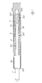
- Figure 1 shows a first embodiment of the contact according to the present invention
- 1 denotes the pin of said contact.
- This pin is provided with an end lug 101 which is inserted inside the tubular container body 2, the exit edge of which in the vicinity of the pin is folded inwards in the form of the flange 102, so as to fasten the pin to said body 2.
- the free end 211 of the stem 201 co-operates with the hyperboloid 3 which is inserted by means of its support 103 in the end of the body 2, so as to bear against the shoulder 202.
- the other end of the hyperboloid 3 and its support 103 are inserted, forced, inside the blind cavity 312 of the terminal 302 which therefore completes the constructional form of the contact.
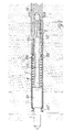
- Figure 2 shows a second embodiment of the contact according to the present invention; parts which are the same are indicated by the same numbers.
- the container body is formed as a single hollow cylindrical element as one piece with the terminal 105; the hyperboloid 3 with its support 103 is inserted in the bottom of the cavity 305 of said body 5.
- the constriction 205 separates the hyperboloid 3 from the spring 4, while the same constriction allows the end 211 of the stem 201 connected to the end lug 101 of the pin 1 to pass through.
- the end lug finally, is locked in position inside the body 5 owing to the constriction 105 formed at the end of the body directed towards the pin 1.
- the pin 1 and its end lug 101 may be easily moved along their axial path allowed by the spring 4, without this resulting in a variation in the conduction efficiency of the contact; in fact, the end 211 of the stem 201 co-operates constantly with the hyperboloid 3, without there being problems due to the movement of the stem 201 itself.
- the fact that the stem is contained within the body 2 or 5, which also houses, partly or completely, the hyperboloid 3, guarantees an axial movement which is guided with the maximum precision, avoiding risks of distortions due to misalignment and consequent nonuniform wear.
- the manufacture and assembly of the contact shown in Figure 1 consists in forming, inside the body 2, the shoulder 202 which is obtained by means of milling or similar procedures; then, on the one hand the spring 4 and on the other hand the hyperboloid 3 with its support 103 are introduced. At this point the pin 1 with its end lug 101 and the stem 201, which passes through the spring 4, the shoulder 202 and is introduced inside the hyperboloid, are inserted; the end opposite to that where the hyperboloid 3 is situated is then clamped so as to form the flange 102. Then, the cavity 312 of the terminal 302 is forced onto the portion of the hyperboloid 3 still projecting outside the body 2, thus forming in this way the complete contact.
- the body 5 is single-piece and at the blind end is provided with the terminal 105.
- the hyperboloid 3 with its support 103 is introduced firstly into the cavity 305 of the body 5; then the wall of the body 5 is deformed so as to create the constriction 205 which at the same time locks the hyperboloid 3 in its seat and ensures location of the spring 4 which is inserted inside the cavity 305. Then it is the turn of the assembly consisting of pin 1, end lug 101 and stem 201, with final tightening obtained by deforming again the wall of the body 5 towards the exit edge of the cavity 305, so as to create the constriction 105.
- the contact designed in this way represents a notable improvement in the context of contacts provided with resilient-tensioning means and is clearly applicable in all those sectors relating to electrical or electronic connections where a high degree of precision and reliability must be combined with mechanical strength and safety.
Landscapes
- Connector Housings Or Holding Contact Members (AREA)
- Coupling Device And Connection With Printed Circuit (AREA)
- Connections Effected By Soldering, Adhesion, Or Permanent Deformation (AREA)
- Multi-Conductor Connections (AREA)
Claims (5)
- Contact pour connexions électriques ou électroniques, comprenant une broche de contact mobile (1,), doté d'un ergot d'extrémité (101) et de moyens de mise en tension élastique (4) qui agissent dans une direction axiale de ladite broche (1), ladite broche étant dotée d'une tige coaxiale (201) qui s'étend à l'extrémité de ladite broche (1) opposée à celle prévue pour la connexion, ladite tige (201) étant introduite à l'intérieur d'un moyen de contact (3) se présentant sous la forme d'un hyperboloïde rainuré (3) ; ladite broche, lesdits moyens de mise en tension élastique (4) et ledit hyperboloïde rainuré (3) étant enfermés à l'intérieur d'un corps de récipient (2, 5) sensiblement cylindrique et sensiblement en une seule pièce, caractérisé par le fait que ledit hyperboloïde rainuré (3) est fixé intérieurement audit corps (2, 5) dans une position à l'extrémité opposée dudit corps (2, 5) par rapport à la position de ladite broche mobile (1) et lesdits moyens de mise en tension élastique (4) sont enveloppés autour de ladite tige (201) d'une manière telle qu'une extrémité desdits moyens de mise en tension élastique (4) est toujours en contact contre ledit ergot d'extrémité (101) et que l'extrémité opposée desdits moyens de mise en tension élastique (4) est toujours en contact contre des moyens de positionnement (202, 205) agencés intérieurement dans ledit corps (2, 5).
- Contact selon la revendication 1, dans lequel ledit corps de récipient (2) est doté, à l'extrémité à laquelle ledit hyperboloïde rainuré (3) est agencé, d'un élément de fermeture (302) qui est relié à la borne dudit contact et est forcé sur ledit hyperboloïde (3).
- Contact selon la revendication 2, dans lequel les moyens de positionnement pour les moyens de mise en tension élastique (4) sont un épaulement (202) qui est formé au moyen d'un fraisage ou de procédés analogues, à l'intérieur dudit corps de récipient (2).
- Contact selon la revendication 1, dans lequel ledit corps de récipient (5) est en une seule pièce, dotée d'une cavité cylindrique borgne (305), et a la borne (105) dudit contact à l'extrémité fermée.
- Contact selon la revendication 4, dans lequel les moyens de positionnement (5) sont obtenus au moyen de rétrécissement des parois du récipient (5) lui-même, à la suite de l'introduction de l'hyperboloïde (3).
Applications Claiming Priority (2)
| Application Number | Priority Date | Filing Date | Title |
|---|---|---|---|
| IT000052A ITGE20060052A1 (it) | 2006-05-05 | 2006-05-05 | Contatto per connessioni elettriche od elettroniche. |
| PCT/EP2007/054212 WO2007128729A1 (fr) | 2006-05-05 | 2007-04-30 | Contact pour connexions électriques ou électroniques |
Publications (2)
| Publication Number | Publication Date |
|---|---|
| EP2016647A1 EP2016647A1 (fr) | 2009-01-21 |
| EP2016647B1 true EP2016647B1 (fr) | 2013-03-20 |
Family
ID=38234470
Family Applications (1)
| Application Number | Title | Priority Date | Filing Date |
|---|---|---|---|
| EP07728666A Active EP2016647B1 (fr) | 2006-05-05 | 2007-04-30 | Contact pour connexions électriques ou électroniques |
Country Status (5)
| Country | Link |
|---|---|
| US (1) | US7857671B2 (fr) |
| EP (1) | EP2016647B1 (fr) |
| CA (1) | CA2651093C (fr) |
| IT (1) | ITGE20060052A1 (fr) |
| WO (1) | WO2007128729A1 (fr) |
Families Citing this family (10)
| Publication number | Priority date | Publication date | Assignee | Title |
|---|---|---|---|---|
| US7805838B2 (en) * | 2007-08-02 | 2010-10-05 | Hypertronics Corporation | Method of forming an electrical connector |
| JP4828617B2 (ja) * | 2009-04-20 | 2011-11-30 | ソニー エリクソン モバイル コミュニケーションズ, エービー | スプリングコネクタ及び端末装置 |
| GB201000344D0 (en) * | 2010-01-11 | 2010-02-24 | Cambridge Silicon Radio Ltd | An improved test probe |
| DE202010003649U1 (de) * | 2010-03-16 | 2010-07-15 | Rosenberger Hochfrequenztechnik Gmbh & Co. Kg | Hochstromsteckverbinder |
| CN101938056B (zh) * | 2010-07-06 | 2013-09-04 | 吴远泽 | 一种插孔电连接器制造方法 |
| FR2971892A1 (fr) * | 2011-02-22 | 2012-08-24 | Souriau | Contact electrique et ensemble connecteur a fort nombre de manoeuvres |
| CA3070124C (fr) | 2015-11-12 | 2022-03-01 | Hunting Titan, Inc. | Ensemble cartouche de piston de contact |
| CN106505348B (zh) * | 2016-11-16 | 2018-06-29 | 李慧敏 | 一种笼式双曲线弹簧结构及插座 |
| CN106887735A (zh) * | 2017-03-03 | 2017-06-23 | 中航光电科技股份有限公司 | 一种电连接器及其线簧插孔 |
| CN111355076A (zh) * | 2018-12-21 | 2020-06-30 | 泰科电子(上海)有限公司 | 电连接器壳体、电连接器、电连接器组件 |
Family Cites Families (16)
| Publication number | Priority date | Publication date | Assignee | Title |
|---|---|---|---|---|
| US2237362A (en) * | 1940-04-20 | 1941-04-08 | Otto A Rieman | Electrical connector |
| US4397519A (en) | 1981-05-12 | 1983-08-09 | Pylon Company, Inc. | Electrical contact construction |
| US4504780A (en) * | 1982-08-25 | 1985-03-12 | Marsella John R | Test probe |
| US4885533B1 (en) * | 1988-09-09 | 1998-11-03 | Qa Technology Co Inc | Electrical circuit test probe having an elongate cylindrical retaining and sliding bearing region |
| US5009613A (en) * | 1990-05-01 | 1991-04-23 | Interconnect Devices, Inc. | Spring contact twister probe for testing electrical printed circuit boards |
| US5529522A (en) * | 1995-03-17 | 1996-06-25 | Huang; Chung-Chuan | Electrical connector |
| JP2003526874A (ja) * | 1998-11-25 | 2003-09-09 | リカ エレクトロニクス インターナショナル インコーポレイテッド | 電気接触装置 |
| US6102746A (en) * | 1999-04-30 | 2000-08-15 | Hypertronics Corporation | Coaxial electrical connector with resilient conductive wires |
| US6213787B1 (en) * | 1999-12-16 | 2001-04-10 | Advanced Interconnections Corporation | Socket/adapter system |
| DE10109719C1 (de) * | 2001-02-28 | 2002-10-24 | Harting Automotive Gmbh & Co | Steckverbinder |
| US6848922B2 (en) * | 2003-03-10 | 2005-02-01 | Hypertronics Corporation | Socket contact with integrally formed arc arresting portion |
| US6861862B1 (en) * | 2003-03-17 | 2005-03-01 | John O. Tate | Test socket |
| DE20315894U1 (de) | 2003-10-16 | 2003-12-18 | Feinmetall Gmbh | Als Federkontaktstift ausgebildeter Hochstromstift |
| DE102004033864A1 (de) * | 2004-07-13 | 2006-02-16 | Era-Contact Gmbh | Elektrischer Druckkontakt |
| JP2006066305A (ja) | 2004-08-30 | 2006-03-09 | Yokowo Co Ltd | スプリングコネクタ |
| ITGE20060051A1 (it) * | 2006-05-05 | 2007-11-06 | Hypertac S P A | Dispositivo di connessione per collegamenti elettrici od elettronici. |
-
2006
- 2006-05-05 IT IT000052A patent/ITGE20060052A1/it unknown
-
2007
- 2007-04-30 CA CA2651093A patent/CA2651093C/fr active Active
- 2007-04-30 EP EP07728666A patent/EP2016647B1/fr active Active
- 2007-04-30 US US12/299,568 patent/US7857671B2/en active Active
- 2007-04-30 WO PCT/EP2007/054212 patent/WO2007128729A1/fr not_active Ceased
Also Published As
| Publication number | Publication date |
|---|---|
| US20090203268A1 (en) | 2009-08-13 |
| EP2016647A1 (fr) | 2009-01-21 |
| CA2651093A1 (fr) | 2007-11-15 |
| WO2007128729A1 (fr) | 2007-11-15 |
| US7857671B2 (en) | 2010-12-28 |
| CA2651093C (fr) | 2014-12-02 |
| ITGE20060052A1 (it) | 2007-11-06 |
Similar Documents
| Publication | Publication Date | Title |
|---|---|---|
| EP2016647B1 (fr) | Contact pour connexions électriques ou électroniques | |
| EP2961004A1 (fr) | Connecteur électrique coaxial radiofréquence avec un élément de contact | |
| US9905968B2 (en) | Coaxial connector with floating mechanism | |
| JP6025224B2 (ja) | 電源端子コネクタ及びシステム | |
| US6952859B2 (en) | Spring hinge | |
| EP2615699A1 (fr) | Connecteur RF | |
| US11171446B2 (en) | Contact for plug connector | |
| US8597065B2 (en) | Sleeve for electrical connectors and method of assembling | |
| KR20110018979A (ko) | 진공 벨로우즈 조립체 제조방법 | |
| RS54060B1 (sr) | Kontaktni element za električni uređaj utičnog priključka | |
| US20110298577A1 (en) | Fuse with counter-bore body | |
| BRPI0609164A2 (pt) | conjunto de cabeçote de suporte de superfìcie dotado de uma superfìcie de alinhamento planar | |
| US9236693B2 (en) | Device for connection of a thermocouple to a safety electromagnet and gas tap assembly in a cooking range | |
| US10283288B2 (en) | Vacuum switching apparatus, and contact assembly and method of securing an electrical contact to an electrode therefor | |
| US7393252B2 (en) | Female electrical contact element and method for making a female electrical contact element | |
| US9350117B2 (en) | Thermocouple and thermocouple connector | |
| US20020187685A1 (en) | Screw terminal | |
| US1291933A (en) | Electrical-circuit-closing contact. | |
| US10559897B1 (en) | Push-in electrical terminal with insulation contact | |
| US20140374632A1 (en) | Thermocouple connector adapted to an electromagnetic gas valve, and thermocouple comprising the connector | |
| US12261402B2 (en) | Spring connector | |
| JP2010257708A (ja) | 電気コネクタ | |
| US20060121762A1 (en) | Elbow-shaped electric plug | |
| CN101364503B (zh) | 一种超小型射频继电器接触系统 | |
| KR200376444Y1 (ko) | 통형상 퓨즈 |
Legal Events
| Date | Code | Title | Description |
|---|---|---|---|
| PUAI | Public reference made under article 153(3) epc to a published international application that has entered the european phase |
Free format text: ORIGINAL CODE: 0009012 |
|
| 17P | Request for examination filed |
Effective date: 20081031 |
|
| AK | Designated contracting states |
Kind code of ref document: A1 Designated state(s): AT BE BG CH CY CZ DE DK EE ES FI FR GB GR HU IE IS IT LI LT LU LV MC MT NL PL PT RO SE SI SK TR |
|
| AX | Request for extension of the european patent |
Extension state: AL BA HR MK RS |
|
| 17Q | First examination report despatched |
Effective date: 20090312 |
|
| DAX | Request for extension of the european patent (deleted) | ||
| GRAP | Despatch of communication of intention to grant a patent |
Free format text: ORIGINAL CODE: EPIDOSNIGR1 |
|
| GRAS | Grant fee paid |
Free format text: ORIGINAL CODE: EPIDOSNIGR3 |
|
| GRAA | (expected) grant |
Free format text: ORIGINAL CODE: 0009210 |
|
| AK | Designated contracting states |
Kind code of ref document: B1 Designated state(s): AT BE BG CH CY CZ DE DK EE ES FI FR GB GR HU IE IS IT LI LT LU LV MC MT NL PL PT RO SE SI SK TR |
|
| REG | Reference to a national code |
Ref country code: GB Ref legal event code: FG4D |
|
| REG | Reference to a national code |
Ref country code: CH Ref legal event code: EP |
|
| REG | Reference to a national code |
Ref country code: IE Ref legal event code: FG4D |
|
| REG | Reference to a national code |
Ref country code: AT Ref legal event code: REF Ref document number: 602573 Country of ref document: AT Kind code of ref document: T Effective date: 20130415 |
|
| REG | Reference to a national code |
Ref country code: DE Ref legal event code: R096 Ref document number: 602007029180 Country of ref document: DE Effective date: 20130516 |
|
| PG25 | Lapsed in a contracting state [announced via postgrant information from national office to epo] |
Ref country code: ES Free format text: LAPSE BECAUSE OF FAILURE TO SUBMIT A TRANSLATION OF THE DESCRIPTION OR TO PAY THE FEE WITHIN THE PRESCRIBED TIME-LIMIT Effective date: 20130701 Ref country code: LT Free format text: LAPSE BECAUSE OF FAILURE TO SUBMIT A TRANSLATION OF THE DESCRIPTION OR TO PAY THE FEE WITHIN THE PRESCRIBED TIME-LIMIT Effective date: 20130320 Ref country code: BG Free format text: LAPSE BECAUSE OF FAILURE TO SUBMIT A TRANSLATION OF THE DESCRIPTION OR TO PAY THE FEE WITHIN THE PRESCRIBED TIME-LIMIT Effective date: 20130620 Ref country code: SE Free format text: LAPSE BECAUSE OF FAILURE TO SUBMIT A TRANSLATION OF THE DESCRIPTION OR TO PAY THE FEE WITHIN THE PRESCRIBED TIME-LIMIT Effective date: 20130320 |
|
| REG | Reference to a national code |
Ref country code: AT Ref legal event code: MK05 Ref document number: 602573 Country of ref document: AT Kind code of ref document: T Effective date: 20130320 |
|
| REG | Reference to a national code |
Ref country code: LT Ref legal event code: MG4D |
|
| PG25 | Lapsed in a contracting state [announced via postgrant information from national office to epo] |
Ref country code: GR Free format text: LAPSE BECAUSE OF FAILURE TO SUBMIT A TRANSLATION OF THE DESCRIPTION OR TO PAY THE FEE WITHIN THE PRESCRIBED TIME-LIMIT Effective date: 20130621 Ref country code: LV Free format text: LAPSE BECAUSE OF FAILURE TO SUBMIT A TRANSLATION OF THE DESCRIPTION OR TO PAY THE FEE WITHIN THE PRESCRIBED TIME-LIMIT Effective date: 20130320 Ref country code: FI Free format text: LAPSE BECAUSE OF FAILURE TO SUBMIT A TRANSLATION OF THE DESCRIPTION OR TO PAY THE FEE WITHIN THE PRESCRIBED TIME-LIMIT Effective date: 20130320 Ref country code: SI Free format text: LAPSE BECAUSE OF FAILURE TO SUBMIT A TRANSLATION OF THE DESCRIPTION OR TO PAY THE FEE WITHIN THE PRESCRIBED TIME-LIMIT Effective date: 20130320 |
|
| REG | Reference to a national code |
Ref country code: NL Ref legal event code: VDEP Effective date: 20130320 |
|
| PG25 | Lapsed in a contracting state [announced via postgrant information from national office to epo] |
Ref country code: BE Free format text: LAPSE BECAUSE OF FAILURE TO SUBMIT A TRANSLATION OF THE DESCRIPTION OR TO PAY THE FEE WITHIN THE PRESCRIBED TIME-LIMIT Effective date: 20130320 |
|
| PG25 | Lapsed in a contracting state [announced via postgrant information from national office to epo] |
Ref country code: NL Free format text: LAPSE BECAUSE OF FAILURE TO SUBMIT A TRANSLATION OF THE DESCRIPTION OR TO PAY THE FEE WITHIN THE PRESCRIBED TIME-LIMIT Effective date: 20130320 Ref country code: EE Free format text: LAPSE BECAUSE OF FAILURE TO SUBMIT A TRANSLATION OF THE DESCRIPTION OR TO PAY THE FEE WITHIN THE PRESCRIBED TIME-LIMIT Effective date: 20130320 Ref country code: PT Free format text: LAPSE BECAUSE OF FAILURE TO SUBMIT A TRANSLATION OF THE DESCRIPTION OR TO PAY THE FEE WITHIN THE PRESCRIBED TIME-LIMIT Effective date: 20130722 Ref country code: RO Free format text: LAPSE BECAUSE OF FAILURE TO SUBMIT A TRANSLATION OF THE DESCRIPTION OR TO PAY THE FEE WITHIN THE PRESCRIBED TIME-LIMIT Effective date: 20130320 Ref country code: IS Free format text: LAPSE BECAUSE OF FAILURE TO SUBMIT A TRANSLATION OF THE DESCRIPTION OR TO PAY THE FEE WITHIN THE PRESCRIBED TIME-LIMIT Effective date: 20130720 Ref country code: CZ Free format text: LAPSE BECAUSE OF FAILURE TO SUBMIT A TRANSLATION OF THE DESCRIPTION OR TO PAY THE FEE WITHIN THE PRESCRIBED TIME-LIMIT Effective date: 20130320 Ref country code: AT Free format text: LAPSE BECAUSE OF FAILURE TO SUBMIT A TRANSLATION OF THE DESCRIPTION OR TO PAY THE FEE WITHIN THE PRESCRIBED TIME-LIMIT Effective date: 20130320 Ref country code: SK Free format text: LAPSE BECAUSE OF FAILURE TO SUBMIT A TRANSLATION OF THE DESCRIPTION OR TO PAY THE FEE WITHIN THE PRESCRIBED TIME-LIMIT Effective date: 20130320 |
|
| PG25 | Lapsed in a contracting state [announced via postgrant information from national office to epo] |
Ref country code: PL Free format text: LAPSE BECAUSE OF FAILURE TO SUBMIT A TRANSLATION OF THE DESCRIPTION OR TO PAY THE FEE WITHIN THE PRESCRIBED TIME-LIMIT Effective date: 20130320 Ref country code: CY Free format text: LAPSE BECAUSE OF FAILURE TO SUBMIT A TRANSLATION OF THE DESCRIPTION OR TO PAY THE FEE WITHIN THE PRESCRIBED TIME-LIMIT Effective date: 20130320 |
|
| REG | Reference to a national code |
Ref country code: CH Ref legal event code: PL |
|
| PG25 | Lapsed in a contracting state [announced via postgrant information from national office to epo] |
Ref country code: MC Free format text: LAPSE BECAUSE OF FAILURE TO SUBMIT A TRANSLATION OF THE DESCRIPTION OR TO PAY THE FEE WITHIN THE PRESCRIBED TIME-LIMIT Effective date: 20130320 |
|
| PLBE | No opposition filed within time limit |
Free format text: ORIGINAL CODE: 0009261 |
|
| STAA | Information on the status of an ep patent application or granted ep patent |
Free format text: STATUS: NO OPPOSITION FILED WITHIN TIME LIMIT |
|
| REG | Reference to a national code |
Ref country code: IE Ref legal event code: MM4A |
|
| PG25 | Lapsed in a contracting state [announced via postgrant information from national office to epo] |
Ref country code: DK Free format text: LAPSE BECAUSE OF FAILURE TO SUBMIT A TRANSLATION OF THE DESCRIPTION OR TO PAY THE FEE WITHIN THE PRESCRIBED TIME-LIMIT Effective date: 20130320 Ref country code: LI Free format text: LAPSE BECAUSE OF NON-PAYMENT OF DUE FEES Effective date: 20130430 Ref country code: CH Free format text: LAPSE BECAUSE OF NON-PAYMENT OF DUE FEES Effective date: 20130430 |
|
| 26N | No opposition filed |
Effective date: 20140102 |
|
| REG | Reference to a national code |
Ref country code: DE Ref legal event code: R097 Ref document number: 602007029180 Country of ref document: DE Effective date: 20140102 |
|
| PG25 | Lapsed in a contracting state [announced via postgrant information from national office to epo] |
Ref country code: IE Free format text: LAPSE BECAUSE OF NON-PAYMENT OF DUE FEES Effective date: 20130430 |
|
| PG25 | Lapsed in a contracting state [announced via postgrant information from national office to epo] |
Ref country code: MT Free format text: LAPSE BECAUSE OF FAILURE TO SUBMIT A TRANSLATION OF THE DESCRIPTION OR TO PAY THE FEE WITHIN THE PRESCRIBED TIME-LIMIT Effective date: 20130320 |
|
| PG25 | Lapsed in a contracting state [announced via postgrant information from national office to epo] |
Ref country code: HU Free format text: LAPSE BECAUSE OF FAILURE TO SUBMIT A TRANSLATION OF THE DESCRIPTION OR TO PAY THE FEE WITHIN THE PRESCRIBED TIME-LIMIT; INVALID AB INITIO Effective date: 20070430 Ref country code: LU Free format text: LAPSE BECAUSE OF NON-PAYMENT OF DUE FEES Effective date: 20130430 |
|
| REG | Reference to a national code |
Ref country code: FR Ref legal event code: PLFP Year of fee payment: 10 |
|
| REG | Reference to a national code |
Ref country code: FR Ref legal event code: PLFP Year of fee payment: 11 |
|
| REG | Reference to a national code |
Ref country code: FR Ref legal event code: PLFP Year of fee payment: 12 |
|
| P01 | Opt-out of the competence of the unified patent court (upc) registered |
Effective date: 20230528 |
|
| PGFP | Annual fee paid to national office [announced via postgrant information from national office to epo] |
Ref country code: DE Payment date: 20250305 Year of fee payment: 19 |
|
| PGFP | Annual fee paid to national office [announced via postgrant information from national office to epo] |
Ref country code: TR Payment date: 20250424 Year of fee payment: 19 |
|
| PGFP | Annual fee paid to national office [announced via postgrant information from national office to epo] |
Ref country code: GB Payment date: 20260312 Year of fee payment: 20 |
|
| PGFP | Annual fee paid to national office [announced via postgrant information from national office to epo] |
Ref country code: IT Payment date: 20260320 Year of fee payment: 20 |
|
| PGFP | Annual fee paid to national office [announced via postgrant information from national office to epo] |
Ref country code: FR Payment date: 20260309 Year of fee payment: 20 |