EP2016653B1 - Bobine d'allumage, en particulier pour un moteur à combustion interne d'un véhicule automobile - Google Patents
Bobine d'allumage, en particulier pour un moteur à combustion interne d'un véhicule automobile Download PDFInfo
- Publication number
- EP2016653B1 EP2016653B1 EP07727839A EP07727839A EP2016653B1 EP 2016653 B1 EP2016653 B1 EP 2016653B1 EP 07727839 A EP07727839 A EP 07727839A EP 07727839 A EP07727839 A EP 07727839A EP 2016653 B1 EP2016653 B1 EP 2016653B1
- Authority
- EP
- European Patent Office
- Prior art keywords
- contact
- ignition coil
- contact sleeve
- sleeve
- retaining element
- Prior art date
- Legal status (The legal status is an assumption and is not a legal conclusion. Google has not performed a legal analysis and makes no representation as to the accuracy of the status listed.)
- Active
Links
Images

Classifications
-
- H—ELECTRICITY
- H01—ELECTRIC ELEMENTS
- H01F—MAGNETS; INDUCTANCES; TRANSFORMERS; SELECTION OF MATERIALS FOR THEIR MAGNETIC PROPERTIES
- H01F38/00—Adaptations of transformers or inductances for specific applications or functions
- H01F38/12—Ignition, e.g. for IC engines
-
- H—ELECTRICITY
- H01—ELECTRIC ELEMENTS
- H01F—MAGNETS; INDUCTANCES; TRANSFORMERS; SELECTION OF MATERIALS FOR THEIR MAGNETIC PROPERTIES
- H01F38/00—Adaptations of transformers or inductances for specific applications or functions
- H01F38/12—Ignition, e.g. for IC engines
- H01F2038/122—Ignition, e.g. for IC engines with rod-shaped core
-
- H—ELECTRICITY
- H01—ELECTRIC ELEMENTS
- H01F—MAGNETS; INDUCTANCES; TRANSFORMERS; SELECTION OF MATERIALS FOR THEIR MAGNETIC PROPERTIES
- H01F27/00—Details of transformers or inductances, in general
- H01F27/02—Casings
- H01F27/04—Leading of conductors or axles through casings, e.g. for tap-changing arrangements
-
- H—ELECTRICITY
- H01—ELECTRIC ELEMENTS
- H01F—MAGNETS; INDUCTANCES; TRANSFORMERS; SELECTION OF MATERIALS FOR THEIR MAGNETIC PROPERTIES
- H01F27/00—Details of transformers or inductances, in general
- H01F27/40—Structural association with built-in electric component, e.g. fuse
-
- H—ELECTRICITY
- H01—ELECTRIC ELEMENTS
- H01F—MAGNETS; INDUCTANCES; TRANSFORMERS; SELECTION OF MATERIALS FOR THEIR MAGNETIC PROPERTIES
- H01F41/00—Apparatus or processes specially adapted for manufacturing or assembling magnets, inductances or transformers; Apparatus or processes specially adapted for manufacturing materials characterised by their magnetic properties
- H01F41/02—Apparatus or processes specially adapted for manufacturing or assembling magnets, inductances or transformers; Apparatus or processes specially adapted for manufacturing materials characterised by their magnetic properties for manufacturing cores, coils, or magnets
- H01F41/04—Apparatus or processes specially adapted for manufacturing or assembling magnets, inductances or transformers; Apparatus or processes specially adapted for manufacturing materials characterised by their magnetic properties for manufacturing cores, coils, or magnets for manufacturing coils
- H01F41/10—Connecting leads to windings
-
- H—ELECTRICITY
- H01—ELECTRIC ELEMENTS
- H01F—MAGNETS; INDUCTANCES; TRANSFORMERS; SELECTION OF MATERIALS FOR THEIR MAGNETIC PROPERTIES
- H01F5/00—Coils
- H01F5/04—Arrangements of electric connections to coils, e.g. leads
Definitions
- the invention relates to an ignition coil, in particular for an internal combustion engine of a motor vehicle according to the preamble of claim 1.
- Such an ignition coil is from the DE 102 51 840 A1 known.
- the known ignition coil of the end portion of a secondary bobbin is received together with a contact sleeve of a cup-like end portion of a high voltage bolt ( FIG. 4 ).
- the high-voltage pin protrudes up to a stop on the secondary coil body zoom, which in turn serves as a stop for the contact sleeve.
- contact sleeve and high-voltage pin end in the same plane.
- the contact sleeve Since the contact sleeve has relatively sharp corners and edges as a result of their formation as a stamped part, cracks can be caused by these regions during operation of the ignition coil due to the different thermal expansion coefficients of the materials under varying temperatures. If the cracks extend over a larger area in the ignition coil housing, there is a risk of flashovers that affect the functioning of the ignition coil.
- the ignition coil according to the invention in particular for an internal combustion engine of a motor vehicle, with the features of claim 1 has the advantage that the extent of cracks is limited or limited in thermomechanical stress of the ignition coil. This is achieved according to the invention essentially in that the hold-down element surrounding the contact sleeve projects beyond or covers the contact sleeve that cracks emanating from corners or edges of the contact sleeve still terminate within the hold-down element, and can not expand further outside the hold-down element in the housing of the ignition coil.
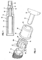
- the ignition coil 10 has an existing plastic, substantially sleeve-shaped housing 11 from.
- a secondary coil body 13 is inserted with a secondary winding 14.
- the high voltage carrying secondary winding 14 provides the ignition energy for a spark plug, not shown, of an internal combustion engine.
- the secondary coil body 13 has a smaller diameter portion 16, on which the one contacting the spark plug one end of the secondary winding 14 is wound.
- About the end portion 17 of the section 16 is a made of electrically conductive metal contact sleeve 18 is pushed.
- the contact sleeve 18 has a circular or annular portion 19, emanate from the bent contact tabs 20.
- the contact sleeve 18 is preferably produced by a stamping process in which the contact tabs 20 are bent from the region 19 after punching.
- the contact tabs 20 contact areas 21, which after the Sliding the contact sleeve 18 on the end portion 17 of the secondary coil body 13 in register with the arranged in section 16 secondary winding 14 are.
- the contact tabs 20 are on the side facing away from the region 19 of the contact portions 21 radially bent slightly outwards and end in hold-down sections 22. From area 19 of the contact sleeve 18 protrude at uniform angular intervals in the embodiment, three triangular contact ribs 24 inside.
- the hold-down element 25 is made in the illustrated embodiment of sheet metal by a non-cutting forming process, and has on the contact sleeve 18 side facing a radially outwardly widening insertion region 26.
- the material of the hold-down element 25 is flanged so that a rounded inlet edge 27 results without sharp corners or edges.
- the length of the hold-down element 25 is dimensioned such that when reaching in the FIG. 3 illustrated end position of the hold-down element 25 of the insertion 26 is viewed with its leading edge 27 in the direction of the secondary bobbin 13 behind the contact plates 20.
- the contact tabs 20 are not only covered by the hold-down element 25, but the hold-down element 25 still extends by a certain length, for example by a third or half the length of the contact tabs 20 beyond the contact tabs 20.
- a pin-shaped suppression resistor 31 is inserted in the sleeve-shaped end of the end portion 17 of the secondary coil body 13.
- the interference resistor 31 is integrally connected to a high voltage terminal 32, which in turn electrically contacts the spark plug, not shown.
- the merging of suppression resistor 31 and secondary coil body 13 takes place when mounted on the secondary coil body 13 contact sleeve 18 and hold-down element 25. In this case, the suppression resistor 31 first passes through an opening 33 of the hold-down element 25 to subsequently penetrate through the annular portion 19 of the contact sleeve 18.
- the formation of the contact ribs 24th on the region 19 of the contact sleeve 18 is such that the contact ribs 24 come into operative connection with the circumference of the Entstörwiderstands 31 and thereby penetrate the outer protective layer, so that an electrical connection between the contact sleeve 18 and the high voltage terminal 32 via the suppression resistor 31.
- the housing 11 After mounting the components of the ignition coil 10, the housing 11 is filled with a thermosetting insulating resin, which fills the gaps in the ignition coil 10, and in particular ensures electrical insulation between the voltage-bearing components.
- This insulating resin inter alia also fills the annular space 35 between the hold-down element 25 and the secondary bobbin 13 ( FIG. 3 ).
- the contact sleeve 18 Due to the punching process, the contact sleeve 18 usually has a plurality of relatively sharp corners or edges, in particular the contact tabs 22. From these areas, a risk of cracking in the insulating resin is caused by thermomechanical stresses. If these cracks extend between components having different voltage levels, there is the risk of voltage flashovers which impair the function of the ignition coil 10.
- the hold-down element 25 can not only, as described in the exemplary embodiment, consist of an electrically conductive or non-conductive metal, but can for example also be made of plastic.
- the hold-down element and the high voltage terminal as a combined, one-piece, consisting of conductive metal component 36 are formed.
- contact ribs 24a are provided on the contact sleeve 18a, which are arranged radially outwardly projecting on the contact sleeve 18a.
- the electrical connection is produced in such a way that, when the component 36 is pushed over onto the contact sleeve 18a, the contact ribs 24a make electrical contact with the component 36 on its inner wall.
- the length of the component 36 such that its insertion 37 clearly overlap the contact tabs 22a of the contact sleeve 18a in the final position of the component 36 and thus emanating from the contact sleeve 18a propagation of cracks in the insulating resin outside of the component 36 can be avoided.
Landscapes
- Engineering & Computer Science (AREA)
- Power Engineering (AREA)
- Ignition Installations For Internal Combustion Engines (AREA)
Claims (6)
- Bobine d'allumage (10), en particulier pour un moteur à combustion interne d'un véhicule automobile, comprenant un enroulement secondaire (14) disposé sur un corps de bobine (13) pour la production d'une haute tension sur une bougie d'allumage, comprenant une douille de contact (18 ; 18a) en contact électrique avec l'enroulement secondaire (14), laquelle peut être glissée sur une région d'extrémité (17) du corps de bobine (13) et comprend au moins un élément de contact (22 ; 22a) pour l'enroulement secondaire (14), et comprenant un élément de retenue (25 ; 36) pouvant être glissé sur la douille de contact (18 ; 18a), lequel agit sur l'au moins un élément de contact (22 ; 22a) de la douille de contact (28 ; 18a), l'élément de retenue (25 ; 36), dans sa position finale, et considéré dans la direction axiale du corps de bobine (13), faisant saillie au-delà de l'au moins un élément de contact (22 ; 22a) de la douille de contact (18 ; 18a) et recouvrant l'au moins un élément de contact (22 ; 22a), caractérisée en ce que la douille de contact (18) comprend au moins un élément de contact (24) faisant saillie radialement vers l'intérieur à partir d'une région annulaire (19) de la douille de contact (18) et en ce que l'au moins un élément de contact (24) est électriquement en connexion fonctionnelle avec une résistance d'anti-parasitage (31) qui pour sa part est connectée à une borne de haute tension (32) pouvant être accouplée à la bougie d'allumage.
- Bobine d'allumage selon la revendication 1, caractérisée en ce que l'élément de retenue (25 ; 36) est réalisé de manière arrondie dans sa région d'entrée (26 ; 37) du côté tourné vers le corps de bobine (13).
- Bobine d'allumage selon la revendication 2, caractérisée en ce que l'élément de retenue (25) est constitué de métal et en ce que la région d'entrée (26) est réalisée de manière rabattue.
- Bobine d'allumage selon l'une quelconque des revendications 1 à 3, caractérisée en ce que l'élément de retenue fait partie intégrante d'une borne de haute tension (36) pour la bougie d'allumage.
- Bobine d'allumage selon la revendication 4, caractérisée en ce que la douille de contact (18a) comprend au moins un élément de contact (24a) faisant saillie radialement vers l'extérieur, lequel peut être mis en contact électrique avec la borne de haute tension (36).
- Bobine d'allumage selon l'une quelconque des revendications 1 à 5, caractérisée en ce que la douille de contact (18 ; 18a) comprend des contacts (22 ; 22a) de type languette pour l'enroulement secondaire (14), et en ce que l'élément de retenue (25 ; 36), dans sa position finale, et considéré dans la direction du corps de bobine (13), dépasse au-delà des contacts (22 ; 22a), en particulier en ce que la région de l'élément de retenue (25 ; 36) dépassant au-delà des contacts (22 ; 22a) dépasse au-delà des contacts (22 ; 22a) d'un tiers jusqu'à la moitié de leur longueur.
Applications Claiming Priority (2)
| Application Number | Priority Date | Filing Date | Title |
|---|---|---|---|
| DE102006020170A DE102006020170A1 (de) | 2006-05-02 | 2006-05-02 | Zündspule, insbesondere für eine Brennkraftmaschine eines Kraftfahrzeugs |
| PCT/EP2007/053371 WO2007125008A1 (fr) | 2006-05-02 | 2007-04-05 | Bobine d'allumage, en particulier pour un moteur à combustion interne d'un véhicule automobile |
Publications (2)
| Publication Number | Publication Date |
|---|---|
| EP2016653A1 EP2016653A1 (fr) | 2009-01-21 |
| EP2016653B1 true EP2016653B1 (fr) | 2013-02-13 |
Family
ID=38255112
Family Applications (1)
| Application Number | Title | Priority Date | Filing Date |
|---|---|---|---|
| EP07727839A Active EP2016653B1 (fr) | 2006-05-02 | 2007-04-05 | Bobine d'allumage, en particulier pour un moteur à combustion interne d'un véhicule automobile |
Country Status (6)
| Country | Link |
|---|---|
| US (1) | US8439023B2 (fr) |
| EP (1) | EP2016653B1 (fr) |
| JP (1) | JP4881431B2 (fr) |
| CN (1) | CN101432937B (fr) |
| DE (1) | DE102006020170A1 (fr) |
| WO (1) | WO2007125008A1 (fr) |
Families Citing this family (3)
| Publication number | Priority date | Publication date | Assignee | Title |
|---|---|---|---|---|
| JP4701835B2 (ja) | 2004-07-27 | 2011-06-15 | 株式会社デンソー | スティック形点火コイル |
| US9356433B2 (en) | 2012-05-10 | 2016-05-31 | Denso International America, Inc. | Ignition coil captured resistor |
| DE102012221897A1 (de) * | 2012-11-29 | 2014-06-05 | Robert Bosch Gmbh | Elektrische Kontaktanordnung zur Kontaktierung einer Spule |
Family Cites Families (20)
| Publication number | Priority date | Publication date | Assignee | Title |
|---|---|---|---|---|
| US3716038A (en) * | 1971-03-31 | 1973-02-13 | Motorola Inc | High voltage coil boot |
| DE3830763C2 (de) * | 1988-09-09 | 1998-04-09 | Siemens Ag | Elektrische Verbindungsvorrichtung |
| JP3473817B2 (ja) * | 1996-10-18 | 2003-12-08 | 株式会社デンソー | 内燃機関用点火コイル |
| JP3709934B2 (ja) * | 1996-10-18 | 2005-10-26 | 株式会社デンソー | 内燃機関用点火コイル |
| JPH10149933A (ja) * | 1996-11-19 | 1998-06-02 | Hitachi Ltd | 点火コイル及びこれを用いた内燃機関 |
| JPH11238637A (ja) * | 1998-02-23 | 1999-08-31 | Toyota Motor Corp | 点火装置 |
| JPH11265832A (ja) * | 1998-03-17 | 1999-09-28 | Toyota Motor Corp | 内燃機関用点火コイル |
| JP4051591B2 (ja) * | 1999-07-08 | 2008-02-27 | 株式会社デンソー | 点火コイル |
| US6178957B1 (en) * | 1999-09-08 | 2001-01-30 | Visteon Global Technologies, Inc. | Pencil ignition coil assembly module |
| US6522232B2 (en) * | 2001-04-26 | 2003-02-18 | Delphi Technologies, Inc. | Ignition apparatus having reduced electric field HV terminal arrangement |
| JP4032692B2 (ja) * | 2001-10-16 | 2008-01-16 | 株式会社デンソー | 点火コイル |
| JP3918610B2 (ja) * | 2002-04-01 | 2007-05-23 | 株式会社デンソー | 内燃機関用点火装置 |
| DE10251841A1 (de) * | 2002-11-07 | 2004-05-19 | Robert Bosch Gmbh | Elektrische Kontaktierung dünner Lackdrähte von Sekundärwicklungen von Zündspulen |
| DE10251840A1 (de) | 2002-11-07 | 2004-05-19 | Robert Bosch Gmbh | Elektrische Kontaktierung dünner Lackdrähte von Sekundärwicklungen von Zündspulen |
| DE10304138B3 (de) * | 2003-02-03 | 2004-07-15 | Robert Bosch Gmbh | Zündspule mit einer Verbindungseinrichtung zur Kontaktierung mit einer Zündkerze |
| DE102004002935A1 (de) | 2004-01-21 | 2005-08-11 | Robert Bosch Gmbh | Elektrische Kontaktierung dünner Lackdrähte von Sekundärwicklungen von Zündspulen mit Kontaktkrone und Kontaktelement |
| DE102004003216B3 (de) * | 2004-01-22 | 2005-08-25 | Era Ag | Zündspule für eine Brennkraftmaschine |
| US7142080B2 (en) * | 2004-02-09 | 2006-11-28 | Denso Corporation | Stick-type ignition coil and terminal assembly therefor |
| JP4701835B2 (ja) | 2004-07-27 | 2011-06-15 | 株式会社デンソー | スティック形点火コイル |
| JP4064382B2 (ja) * | 2004-08-03 | 2008-03-19 | 阪神エレクトリック株式会社 | 内燃機関用点火コイル |
-
2006
- 2006-05-02 DE DE102006020170A patent/DE102006020170A1/de not_active Withdrawn
-
2007
- 2007-04-05 JP JP2009508287A patent/JP4881431B2/ja active Active
- 2007-04-05 EP EP07727839A patent/EP2016653B1/fr active Active
- 2007-04-05 US US12/299,279 patent/US8439023B2/en active Active
- 2007-04-05 CN CN2007800158051A patent/CN101432937B/zh active Active
- 2007-04-05 WO PCT/EP2007/053371 patent/WO2007125008A1/fr not_active Ceased
Also Published As
| Publication number | Publication date |
|---|---|
| US20090301450A1 (en) | 2009-12-10 |
| CN101432937A (zh) | 2009-05-13 |
| EP2016653A1 (fr) | 2009-01-21 |
| JP2009535828A (ja) | 2009-10-01 |
| WO2007125008A1 (fr) | 2007-11-08 |
| DE102006020170A1 (de) | 2007-11-08 |
| JP4881431B2 (ja) | 2012-02-22 |
| US8439023B2 (en) | 2013-05-14 |
| CN101432937B (zh) | 2012-06-27 |
Similar Documents
| Publication | Publication Date | Title |
|---|---|---|
| EP3022804B1 (fr) | Dispositif de mise en contact électrique d'un blindage de câble électrique avec un boîtier, et câble électrique préfabriqué | |
| DE102009035897B4 (de) | Zündkerze sowie Zündanordnung umfassend eine Zündspule und -kerze | |
| EP3608521B1 (fr) | Tige de soutien et catalyseur | |
| EP2165070B1 (fr) | Bobine d'allumage | |
| WO2012095252A1 (fr) | Bobine d'allumage, en particulier pour moteurs de petites dimensions | |
| EP3363064B1 (fr) | Pôle de batterie et unité de contact électrique pour établir une connexion électrique entre un pôle de batterie et le système électrique d'un véhicule | |
| EP2016653B1 (fr) | Bobine d'allumage, en particulier pour un moteur à combustion interne d'un véhicule automobile | |
| EP2050171B1 (fr) | Bougie d'allumage a espace de montage reduit | |
| WO2017121524A1 (fr) | Bougie d'allumage comprenant une encoche ou une rainure dans l'isolateur ou dans le boîtier | |
| EP1563520B1 (fr) | Etablissement d'un contact electrique entre des fils laques fins d'enroulements secondaires de bobines d'allumage | |
| EP1563519B1 (fr) | Mise en contact electrique de fils laques fins d'enroulements secondaires de bobines d'allumage | |
| DE102004007357B4 (de) | HF-Steckkontakt mit einer Crimphülse und Crimphülse für einen HF-Steckkontakt | |
| EP2761710B1 (fr) | Bougie d'allumage améliorée | |
| DE10004313B4 (de) | Dieselkraftstoff-Einspritzdüse | |
| DE10020558C1 (de) | Glühstift | |
| DE102015101568A1 (de) | Koronazündeinrichtung mit einer Abschirmung aus Schalenelemen | |
| DE102016211166A1 (de) | Metallglühstiftkerze und Dichtungskörper dafür | |
| DE29520528U1 (de) | Verbindungsvorrichtung für Zündanlagen von Kraftfahrzeugen | |
| DE102008040285A1 (de) | Bauraumoptimierte Zündkerze | |
| DE102020211352A1 (de) | Vorkammerzündkerze mit verbesserter Masseelektrode | |
| DE29617417U1 (de) | Stabspule für Zündanlagen | |
| DE102018125456A1 (de) | Zündkerze sowie Verfahren zum Herstellen einer Elektrode | |
| DE102018110580A1 (de) | Zündkerze für eine Brennkraftmaschine | |
| DE1121149B (de) | Loesbare Verbindung fuer zwei elektrische Leiter | |
| DE102004049287A1 (de) | Verbindung einer Zündkerze mit einer Zündspule |
Legal Events
| Date | Code | Title | Description |
|---|---|---|---|
| PUAI | Public reference made under article 153(3) epc to a published international application that has entered the european phase |
Free format text: ORIGINAL CODE: 0009012 |
|
| 17P | Request for examination filed |
Effective date: 20081202 |
|
| AK | Designated contracting states |
Kind code of ref document: A1 Designated state(s): AT BE BG CH CY CZ DE DK EE ES FI FR GB GR HU IE IS IT LI LT LU LV MC MT NL PL PT RO SE SI SK TR |
|
| AX | Request for extension of the european patent |
Extension state: AL BA HR MK RS |
|
| RBV | Designated contracting states (corrected) |
Designated state(s): DE |
|
| 17Q | First examination report despatched |
Effective date: 20100806 |
|
| DAX | Request for extension of the european patent (deleted) | ||
| GRAP | Despatch of communication of intention to grant a patent |
Free format text: ORIGINAL CODE: EPIDOSNIGR1 |
|
| GRAS | Grant fee paid |
Free format text: ORIGINAL CODE: EPIDOSNIGR3 |
|
| GRAA | (expected) grant |
Free format text: ORIGINAL CODE: 0009210 |
|
| AK | Designated contracting states |
Kind code of ref document: B1 Designated state(s): DE |
|
| REG | Reference to a national code |
Ref country code: DE Ref legal event code: R096 Ref document number: 502007011298 Country of ref document: DE Effective date: 20130404 |
|
| PLBE | No opposition filed within time limit |
Free format text: ORIGINAL CODE: 0009261 |
|
| STAA | Information on the status of an ep patent application or granted ep patent |
Free format text: STATUS: NO OPPOSITION FILED WITHIN TIME LIMIT |
|
| 26N | No opposition filed |
Effective date: 20131114 |
|
| REG | Reference to a national code |
Ref country code: DE Ref legal event code: R097 Ref document number: 502007011298 Country of ref document: DE Effective date: 20131114 |
|
| PGFP | Annual fee paid to national office [announced via postgrant information from national office to epo] |
Ref country code: DE Payment date: 20250624 Year of fee payment: 19 |