EP2016688B1 - Vierpolige übertragung - Google Patents
Vierpolige übertragung Download PDFInfo
- Publication number
- EP2016688B1 EP2016688B1 EP07733630A EP07733630A EP2016688B1 EP 2016688 B1 EP2016688 B1 EP 2016688B1 EP 07733630 A EP07733630 A EP 07733630A EP 07733630 A EP07733630 A EP 07733630A EP 2016688 B1 EP2016688 B1 EP 2016688B1
- Authority
- EP
- European Patent Office
- Prior art keywords
- antennas
- polarisations
- antenna
- pair
- spatial
- Prior art date
- Legal status (The legal status is an assumption and is not a legal conclusion. Google has not performed a legal analysis and makes no representation as to the accuracy of the status listed.)
- Not-in-force
Links
- 230000005540 biological transmission Effects 0.000 title claims abstract description 50
- 238000004891 communication Methods 0.000 claims abstract description 44
- 230000009977 dual effect Effects 0.000 claims abstract description 21
- 238000000034 method Methods 0.000 claims abstract description 18
- 238000000926 separation method Methods 0.000 description 29
- 230000010363 phase shift Effects 0.000 description 15
- 230000004044 response Effects 0.000 description 11
- 230000008878 coupling Effects 0.000 description 10
- 238000010168 coupling process Methods 0.000 description 10
- 238000005859 coupling reaction Methods 0.000 description 10
- 238000004088 simulation Methods 0.000 description 10
- 239000011159 matrix material Substances 0.000 description 7
- 238000010586 diagram Methods 0.000 description 4
- 239000006185 dispersion Substances 0.000 description 3
- 230000000694 effects Effects 0.000 description 3
- 230000003068 static effect Effects 0.000 description 3
- 230000008901 benefit Effects 0.000 description 2
- 239000000835 fiber Substances 0.000 description 2
- 230000003595 spectral effect Effects 0.000 description 2
- 238000003491 array Methods 0.000 description 1
- 238000005452 bending Methods 0.000 description 1
- 230000008859 change Effects 0.000 description 1
- 238000001514 detection method Methods 0.000 description 1
- 230000004069 differentiation Effects 0.000 description 1
- 238000009434 installation Methods 0.000 description 1
- 230000002452 interceptive effect Effects 0.000 description 1
- 238000002955 isolation Methods 0.000 description 1
- 230000008569 process Effects 0.000 description 1
- 230000003362 replicative effect Effects 0.000 description 1
- 238000007493 shaping process Methods 0.000 description 1
- 238000001228 spectrum Methods 0.000 description 1
Images


Classifications
-
- H—ELECTRICITY
- H04—ELECTRIC COMMUNICATION TECHNIQUE
- H04B—TRANSMISSION
- H04B7/00—Radio transmission systems, i.e. using radiation field
- H04B7/02—Diversity systems; Multi-antenna system, i.e. transmission or reception using multiple antennas
- H04B7/10—Polarisation diversity; Directional diversity
-
- H—ELECTRICITY
- H01—ELECTRIC ELEMENTS
- H01Q—ANTENNAS, i.e. RADIO AERIALS
- H01Q21/00—Antenna arrays or systems
- H01Q21/24—Combinations of antenna units polarised in different directions for transmitting or receiving circularly and elliptically polarised waves or waves linearly polarised in any direction
Definitions
- the present invention relates to improved methods and apparatus for transmitting multiple signals on a single frequency, particularly for communications over fixed wireless point-to-point communications links.
- Such fixed links include radio and microwave communication arrangements which communicate on a line-of-sight arrangement between transmit and receive antennas. Examples include communications between mobile telephone masts and their networks, and dedicated point-to-point links between buildings.
- Such fixed links may be used as an alternative to an optic fibre path, in situations where installation of an optic fibre link would be impractical, for example due to inhospitable terrain or a temporary nature of the required link.
- the present invention may, however, be applied to any point-to-point fixed link.
- MIMO is an abbreviation for "Multiple In, Multiple Ouf”. It signifies a communications arrangement in which multiple signals can be transmitted and received over a single communications link on a single frequency. This is typically achieved by use of multiple transmit antennas, and multiple receive antennas, and provides improved spectral efficiency as compared to more conventional arrangements where only one signal could be transmitted on a given link at a given frequency. Certain examples will now be described.
- FIG. 1 schematically illustrates a MIMO communications arrangement of the prior art.
- a fixed link communication arrangement comprises a pair of antennas 10a and 10b at a transmitter location 10, and a pair of antennas 12a, 12b at a receiver location 12.
- each pair of antennas would be spaced by a distance d in a direction orthogonal to a line of sight between locations 10, 12.
- both antenna pairs would be vertically spaced; alternatively, both antenna pairs would be horizontally spaced.
- Arrangements in which one antenna pair is horizontally spaced and the other antenna pair is vertically spaced are possible, but are not presently preferred. Arrangements in which the spacing of the antennas of each pair is neither vertical nor horizontal, but intermediate, are also possible.
- each of the locations 10, 12, will typically provide both receive and transmit functions, but the functions are separated for the purposes of the present explanation.
- Fig. 1 is not drawn to scale, but some dimensions are exaggerated for the purposes of explanation.
- Paths 14, 16, 18, 20 are co-spatial paths: antenna 10a is transmitting to corresponding antenna 12a, and antenna 10b is transmitting to corresponding antenna 12b.
- the length of these paths is equal to l , the distance between the locations.
- cross-spatial path 18 results from antenna 10b transmitting to opposite antenna 12a
- cross-spatial path 20 results from antenna 10a transmitting to opposite antenna 12b.
- the difference in path length, a will in reality be very small.
- This difference in path length a will cause a difference in phase of received signals. For example, if the communications in question use a wavelength ⁇ of 0.0020m, then this difference in path length a will cause difference in the phase of signals received at the antennas 12a, 12b of one quarter wavelength ( ⁇ /4).
- four different signals may be transmitted by the arrangement of Fig. 1 . In a typical arrangement, one signal is transmitted on each of the paths 14, 16, 18, 20. Of course, each antenna will receive all of the transmitted signals, but phase differences can be used to distinguish between them at each antenna.
- a first co-spatial path 14 travels from antenna 10a to antenna 12a.
- a first cross-spatial path 18 travels from antenna 10b to antenna 12a.
- the signal on first cross-spatial path 18 will phase lag the signal on first co-spatial path 14 at the receiving antenna 12a, by an amount corresponding to the difference in path lengths, a .
- this may be one quarter wavelength ( ⁇ /4), corresponding to a 90° phase difference.
- the signals on first co-spatial path 14 and on the first cross-spatial path 18 may be separated and decoded to extract respective signals.
- a second co-spatial path 16 travels from antenna 10b to antenna 12b.
- a second cross-spatial path 20 travels from antenna 10a to antenna 12b.
- the signal on second cross-spatial path 20 will lag behind the signal on first co-spatial path 16 at the receiving antenna 12b, by an amount corresponding to the difference in path lengths, a . In the example mentioned above, this may be one quarter wavelength ( ⁇ /4), corresponding to a 90° phase difference.
- the signals on the second co-spatial path 16 and on the second cross-spatial path 20 may be separated and decoded to extract respective further signals.
- the attainable phase difference at the receive antennas 12a, 12b will of course depend on the wavelength/frequency of the transmission, the separation d between the transmit antennas, and the separation between the receive antennas, which is conveniently, but not necessarily, fixed at the same separation d as between the transmit antennas.
- the separation d between antennas is preferably kept relatively small, for example in the region of 1m.
- performance of the cross-channel encoding and decoding is improved by having a large phase difference between co-spatial and cross-spatial signals.
- a relatively high frequency/short wavelength is required.
- 38GHz is commonly used for fixed point-to-point links, which provides a wavelength of about 0.008m.
- 7.5GHz is also commonly used for fixed point-to-point links, with a wavelength of about 0.04m. Even higher frequencies are likely to experience atmospheric effects which degrade the transmission.
- the difference in path length a is identical for first and second co-spatial channels 18, 20, this need not be the case.
- the antennas 10a and 10b are separated in a direction parallel to the line of sight between locations 10, 12, in addition to being separated in a direction orthogonal to the line of sight between locations 10, 12 then the difference in path length will be different for first and second cross-spatial channels 18, 20. This need not be a problem, provided that the encoding and/or decoding operations take this into account.
- MIMO communication arrangements have in the past been applied to mobile telephony, for example in communications between base stations and the network, and to wireless LAN networks. Unlike certain other communications arrangements, MIMO communications paths work best with a significant amount of scatter. The diversity introduced by a significant amount of scatter has been found to assist the process of separating the different channels from one another.
- Point-to-point links as described above, very little scattering occurs. This is due to the fact that such point-to-point links are arranged on a line of sight, so the scope for multiple paths and reflection and diffraction around objects is minimal. Some scattering may be provided by multiple paths introduced over long-distance point-to-point fixed links by so-called "ducting", where a gradient in atmospheric refractive index causes the bending of radio or microwave paths, so providing further paths of greater length than the direct line-of-sight path. Point-to-point links have therefore been regarded as a challenging context for the use of MIMO communication arrangements.
- Fig. 1 The preceding description illustrates how four signals, including two cross-spatial signals, may be transmitted on four paths between pairs of antennas as illustrated in Fig. 1 . These numbers may easily be doubled, to eight signals, including four cross-spatial signals, by replicating the arrangement of Fig. 1 in a second polarisation. This is most simply achieved by using dual-polarised antennas for each of the transmit and receive antennas 10a, 10b, 12a, 12b, each providing or receiving both horizontal and vertical polarisation signals. Transmissions of a certain polarisation will be picked up by the receive antenna of the corresponding polarisation, with a tolerable level of interference from signals of the other polarisation, referred to as cross-polarisation interference.
- Each polarisation will provide an arrangement similar to that illustrated in Fig. 1.
- Fig. 2A schematically shows a pair of transmit antennas 10a', 10b', suitable for use as transmit antennas in such an arrangement.
- Each transmit antenna comprises a horizontally polarised antenna and a vertically polarised antenna.
- a similar arrangement is made for the receive antennas.
- Such dual polarisation antennas may be embodied as a dish antenna, as will be apparent to those skilled in the relevant art.
- Use of such dual polarisation cross-channel MIMO communications is referred to as"dual-dual polar" communication.
- the antennas To achieve the quoted levels of cross-spatial interference in a practical link would necessitate the antennas to be widely separated at least equal to the product of the antenna beam width and the link distance. As an example employing antennas with a 1° 3dB beam width in azimuth, then the separation required to achieve 6dB cross-spatial isolation on a 10km link is a rather impractical 174m.
- Such MIMO point-to point links suffer from the problem that a relatively large phase difference is required for effective decoding, and that such a large phase difference requires a large separation d between antennas at the transmit 10 and receive 12 locations.
- the separation d is reduced, the phase difference between co-spatial and cross-spatial paths will reduce, leading to more difficulties in decoding the received transmissions.
- United States patent 7006804 describes high-speed two-way point-to-point transmission. Pairs of dual polar antennas are used, one for transmission and one for reception.
- the present invention provides methods and apparatus which enable improved MIMO communication methods to be employed in point-to-point fixed links.
- the present invention allows effective MIMO communication with reduced phase difference between co-spatial and cross-spatial paths, allowing antennas to be situated with reduced spacing d , or reducing the frequency of operation of antennas with a given spacing d , while maintaining channel capacity.
- the present invention provides methods and apparatus which enable improved MIMO communication, allowing several signals to be transmitted and received on a single frequency, over a fixed point-to-point link, with antennas separated by a limited separation d , employing different polarisation of signals over transmission paths.
- the present invention provides a novel type of antenna arrangement for use in a fixed point-to-point link, this antenna arrangement enabling effective MIMO encoding and decoding of multiple signals on a fixed point-to-point link, while maintaining a reasonably small physical separation between antennas at the transmit location and the receive location.
- the antenna arrangement of the invention is arranged to provide sufficient phase shift between the different signals transmitted on any one frequency, while limiting the required separation between antennas.
- the present invention improves upon the dual-dual polar MIMO transmission method described above in relation to Figs. 1 and 2A .
- one of the two transmit antennas and one of the two receive antennas are oriented so that that antenna transmits orthogonal +45° and - 45° polarisations, while the other antenna transmits orthogonal vertical and horizontal polarisations.
- This configuration is referred to as quad polar transmission, as four different polarisations are involved.
- the antenna configurations used at the receiver are the same as used at the transmitter and are depicted in Figure 2B .
- a pair of quad polar antennas 10a" and 10b" are illustrated in Fig. 2B . These antennas are suitable for use as transmission antennas 10a, 10b in an arrangement as shown in Fig. 1 .
- the transmit antennas do not simply provide horizontal and vertical polarisation, as was the case with dual-dual polarisation. Instead, one antenna, 10a”, provides horizontal and vertical polarisation, while the other antenna 10b", provides two orthogonal polarisations each intermediate between the horizontal and vertical polarisations-for example, +45° and -45° polarisations as compared to the polarisations of the other antenna.
- each of the +45° and -45° polarisations interfere equally with both the horizontal and vertical polarisation of the other antenna.
- each of the horizontal and vertical polarisations interferes equally with both the +45° and -45° polarisations of the other antenna. This makes it easier to detect the interfering signals and to cancel them out, by methods known in themselves to those skilled in the art. This in turn means that a reduced phase shift, and so a reduced difference in path length a can be used. Path length differences a corresponding to ⁇ /8 or ⁇ /16 have been found to be sufficient. The effect of this is that the antenna array at transmit 10 and receive 12 locations may be made smaller, as the antennas may be placed closer together by reducing the separation d .
- +45° and -45° polarisations of the second antenna 10b" with respect to the orthogonal polarisations of the first antenna 10a" is not necessary, as other intermediate orthogonal polarisations may be used.
- an arrangement of +30° and -60° polarisations would provide benefits over the dual-dual arrangement of Fig. 2A , since the +30° and -60° polarisations would interfere with vertical and horizontal polarisations, although not to equal extents.
- orthogonal polarisations defined by orthogonally arranged transmit and receive antennas may in some arrangements be replaced with non-orthogonal polarisations.
- one antenna may be provided with polarisations of +30° and -30° as compared to the vertical.
- polarisations of +30° and -30° as compared to the vertical.
- the channel impulse response matrix under these propagation conditions can then be described by a matrix of complex attenuations, as no time dispersion exists.
- each of these sixteen possible propagation paths is characterised by its own amplitude/attenuation and phase shift.
- a simplified model has been obtained.
- Equation [1] the channel impulse response may be calculated, as shown below in Equation [1], showing the channel impulse response of each of the sixteen possible propagation paths mentioned above.
- H ⁇ 1 - ⁇ 0 ⁇ 0 ⁇ e j ⁇ 0 1 - ⁇ 1 ⁇ e j ⁇ ⁇ 1 ⁇ e j ⁇ ⁇ + ⁇ 1 ⁇ 0 ⁇ e j ⁇ 0 1 - ⁇ 0 ⁇ 1 ⁇ e j ⁇ ⁇ + ⁇ 1 1 - ⁇ 1 ⁇ e j ⁇ 1 - ⁇ 1 ⁇ e j ⁇ ⁇ 1 ⁇ e j ⁇ ⁇ + ⁇ 1 1 - ⁇ 0 ⁇ 0 ⁇ e j ⁇ 0 ⁇ 1 ⁇ e j ⁇ ⁇ + ⁇ 1 1 - ⁇ 0 ⁇ ⁇ e j ⁇ 0 ⁇ 1 ⁇ e j ⁇ ⁇ + ⁇ 1 1 - ⁇ 0 ⁇
- the amplitude of cross-polar coupling between different polarisations received via the co-spatial path is denoted by ⁇ 0 .
- the amplitude and phase shift due to cross-polar coupling received via the cross-spatial paths are given by ⁇ 1 and ⁇ 1 , respectively.
- the theoretical capacity of the two transmission schemes may be evaluated as a function of ⁇ , the phase shift of the cross-spatial path relative to the co-spatial path.
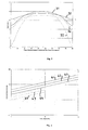
- Fig. 3 illustrates MIMO capacity C MIMO and zero-forcing capacity C ZF for dual-dual polar transmission and quad polar transmission versus the relative phase between co-spatial and cross-spatial paths.
- the MIMO capacities C MIMO represent the theoretical capacity for an ideal receiver in each case, while the zero-forcing capacities C ZF correspond to the capacity which can be realised in practice using a simple practical receiver.
- Curve 31 shows MIMO capacity C MIMO of a dual-dual polar communications link over a range of phase differences between co-spatial and cross-spatial paths of 0 to 180°, with a signal-to-noise ratio of 12dB and -20dB cross-polar interference in units of bits per second per Hz of bandwidth b/s/Hz.
- curve 32 shows the corresponding MIMO capacity C MIMO of a quad polar communications link
- curve 33 shows the corresponding zero forcing capacity C ZF of a dual-dual polar communications link
- curve 34 shows the corresponding zero forcing capacity C ZF of a quad polar communications link.
- Fig. 3 show that the optimum phase difference between the cross-spatial path and the co-spatial path is 90° for both dual-dual polar transmission and quad polar transmission.
- the zero-forcing capacity 33 drops to zero for the dual-dual polar transmission but is only reduced from its peak value in the case of quad polar transmission 34.
- the peak capacity of dual-dual polar transmission 31 is slightly higher than that of quad polar transmission 33.
- the capacities 32, 34 of quad polar transmission are significantly higher than the corresponding capacities 31, 33 of dual-dual transmission at phase differences below 40° and above 140°.
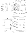
- the actual antenna separations d required to achieve a 90° phase difference ( ⁇ /4 path length difference) between the cross-spatial path and the co-spatial path have been evaluated for typical link lengths l used in the 7.5 and 38GHz bands, and the results plotted in Fig. 4 . Also shown in Fig. 4 are the antenna separations required for 45° phase difference ( ⁇ /8 path length difference) and 22.5° phase difference ( ⁇ /16 path length difference).
- Line 41 shows required antenna separation d for providing a 90° phase difference ( ⁇ /4 path length difference) between the cross-spatial path and the co-spatial path for link lengths l in the range of 1-100km in the 7.5GHz band.
- Line 42 shows required antenna separation d for providing a 45° phase difference ( ⁇ /8 path length difference) between the cross-spatial path and the co-spatial path for link lengths l in the range of 1-100km in the 7.5GHz band.
- Line 43 shows required antenna separation d for providing a 22.5 phase difference ( ⁇ /16 path length difference) between the cross-spatial path and the co-spatial path for link lengths l in the range of 1-100km in the 7.5GHz band.
- Line 44 shows required antenna separation d for providing a 90° phase difference ( ⁇ /4 path length difference) between the cross-spatial path and the co-spatial path for link lengths l in the range of 1-10km in the 38GHz band.
- Line 45 shows required antenna separation d for providing a 45° phase difference ( ⁇ /8 path length difference) between the cross-spatial path and the co-spatial path for link lengths l in the range of 1-10km in the 38GHz band.
- Line 46 shows required antenna separation d for providing a 22.5° phase difference ( ⁇ /16 path length difference) between the cross-spatial path and the co-spatial path for link lengths l in the range of 1-10km in the 38GHz band.
- antenna separations of no more than a few metres are desirable. If an upper limit on the antenna separation is set at 3m, then link lengths of 3 to 9km could be supported at 38GHz, depending upon the relative phase required between co-spatial and cross-spatial paths. At 7.5GHz, antenna separations of 10-20m are required for typical link lengths used in this frequency band.
- the four channels illustrated represent the vertical, horizontal, +45° and - 45° antennas of the described embodiment of the present invention. Similar simulations could be used to model the four channels represented by the vertical and horizontal polarisations of each of the antennas in a dual-dual transmission.
- Blocks of sample data are generated for each of the four channels in modulators 52.
- the blocks are filtered through respective transmit filters 53.
- the transmit filters apply pulse shaping and define the spectrum of the transmitted signal, to simulate real transmission conditions.
- the blocks are then processed through a channel model 56, which applies the propagation conditions as defined in the channel impulse response matrix H , at equation [1] above.
- the channel model 56 is capable of incorporating time dispersion effects on all paths.
- a quantity of white Gaussian noise 59 is added to each channel, to simulate the noise generated within the receiver and received at the antenna terminals.
- the channel impulse response coefficients, as defined in equation [1] are estimated using a block least squares channel estimator 57. In one arrangement of the simulation, knowledge of the block of modulated data symbols is assumed. In a practical embodiment, this would not be possible and other algorithms for computation of tap weights would be used.
- the filter coefficients of a minimum mean square error Decision Feedback Equaliser for the MIMO channel (MIMO-DFE) 58 are calculated, for example by using the method described in N. Al-Dhahir and A.H. Sayed, "The Finite-Length Multi-Input Multi-Output MMSE DFE", IEEE Transactions on Signal Processing, Vol. 48, No. 10, October 2000, pp2921-2935 for obtaining the coefficients.
- the MIMO-DFE is one example of a practical receiver which could be used to receive communications according to the present invention. Other known receivers could alternatively be used.
- the MIMO-DFE 58 of Fig. 5 is shown in more detail. It comprises a 4x4 matrix of transversal filters (Forward Filter) 62 that essentially performs most of the cross-spatial and cross-polar interference cancellation, to remove interference between channels and to attempt to remove inter-symbol interference. Decision devices 68 act on incoming decision variables and are used to obtain estimates 66 of the transmitted modulated symbols, which are the outputs of the 4x4 MIMO DFE.
- Forward Filter Transversal filters
- Further cancellation of inter-symbol cross-spatial and cross-polar interference can be performed using a 4 ⁇ 4 matrix of transversal filters of the feedback filter 64 whose inputs 66 are previous symbol decisions from decision devices 68.
- the decision variables used by decision devices 68 are then modified by subtraction 71 of outputs 69 of the feedback filter 64 from outputs 70 of the forward filter 62.
- Residual interference will exist at decision instants and it is possible to consider not just a simple decision device, but also more complex decision devices using serial interference cancellation [for example, as discussed in G.D. Golden, G.J. Foschini, R.A. Valenzuela and P.W. Wolniansky, "Detection Algorithm and Initial Laboratory Results using the V-BLAST Space-Time Communications Architecture", Electronics Letters, Vol. 35, No. 7, January 1999, pp14-15 ], or the optimum decision device that makes a joint decision considering the residual interference.
- FIG. 7 illustrates static channel simulation results for various communications links, in terms of variation of bit error rate (BER) with signal-to-noise ratio.
- BER bit error rate
- Line 70 shows a reference 64-bit quadrature amplitude modulation scheme
- Line 71 shows a dual-dual polar communications link with a phase offset of 90°
- Line 72 shows a quad polar communications link according to the invention, with a phase offset of 90°
- Line 73 shows a quad polar communications link according to the invention, with a phase offset of 45°
- Line 74 shows a dual-dual polar communications link with a phase offset of 45°
- Line 75 shows a dual-dual polar communications link with a phase offset of 22.5°
- Line 76 shows a quad polar communications link according to the invention, with a phase offset of 22.5°
- Line 77 shows a single polar dual antenna receiver communications link.
- the present invention accordingly provides improved methods and apparatus for MIMO communications across wireless fixed links, wherein a pair of spaced dual polar antennas are used for transmission, and another such pair are used for reception, wherein orthogonal polarisations of one of each pair of antennas are oriented intermediate between the orthogonal polarisations of the other of each pair of antennas.
- Improved communications are provided with polarisation offsets between the antennas of each pair in at least the range 22.5° to 67.5°.
Landscapes
- Engineering & Computer Science (AREA)
- Computer Networks & Wireless Communication (AREA)
- Signal Processing (AREA)
- Radio Transmission System (AREA)
- Optical Communication System (AREA)
- Variable-Direction Aerials And Aerial Arrays (AREA)
- Ultra Sonic Daignosis Equipment (AREA)
- Mobile Radio Communication Systems (AREA)
- Materials For Photolithography (AREA)
- ing And Chemical Polishing (AREA)
Claims (10)
- Vorrichtung für MIMO-Kommunikation über einen drahtlosen festen Link, umfassend ein erstes Paar (10) von Dual-Polar-Antennen, die in einer zur Richtung (l) des festen Link orthogonalen Richtung (d) voneinander beabstandet sind, und ein zweites solches Paar (12) für den Empfang, dadurch gekennzeichnet, dass die Polarisationen einer Dual-Polar-Antenne (10a") jedes Paares (10, 12) von Dual-Polar-Antennen intermediär zwischen den Polarisationen der anderen Dual-Polar-Antenne (10b") des betreffenden selben Paares (10) orientiert sind.
- Vorrichtung nach Anspruch 1, wobei jede Dual-Polar-Antenne mit orthogonalen Polarisationen angeordnet ist.
- Vorrichtung nach Anspruch 2, wobei Polarisationsverschiebungen zwischen den orthogonalen Polarisationen der Antennen jedes Paares in dem Bereich von 22,5° bis 67,5° liegen.
- Vorrichtung nach Anspruch 3, wobei Polarisationsverschiebungen zwischen den orthogonalen Polarisationen der Antennen jedes Paares in dem Bereich von 30° bis 60° liegen.
- Vorrichtung nach Anspruch 4, wobei Polarisationsverschiebungen zwischen den orthogonalen Polarisationen der Antennen jedes Paares 45° betragen.
- Verfahren für MIMO-Kommunikation über einen drahtlosen festen Link, wobei ein erstes Paar (10) von Dual-Polar-Antennen, die in einer zur Richtung (/) des festen Link orthogonalen Richtung beabstandet sind (d), für die Übertragung verwendet werden und ein zweites solches Paar (12) für den Empfang verwendet wird, dadurch gekennzeichnet, dass Polarisationen einer Dual-Polar-Antenne (10a") jedes Paares (10, 12) von Dual-Polar-Antennen intermediär zwischen den Polarisationen der anderen Dual-Polar-Antenne (10b") des betreffenden selben Paares orientiert werden, wobei das Verfahren die folgenden Schritte umfasst:- das Übertragen erster und zweiter Signale mit ersten und zweiten Polarisationen von einer ersten Dual-Polar-Antenne (10a") des ersten Paares (10);- das Übertragen dritter und vierter Signale mit dritten und vierten Polarisationen von einer zweiten Dual-Polar-Antenne (10b") des ersten Paares, derart, dass die dritten und vierten Polarisationen intermediär zwischen den ersten und zweiten Polarisationen orientiert sind und die ersten, zweiten, dritten und vierten Signale gleiche Frequenz haben;- das Empfangen der ersten, zweiten, dritten und vierten Signale in dem zweiten Paar (12) von Dual-Polar-Antennen;- das Trennen der empfangenen ersten, zweiten, dritten und vierten Signale in Übereinstimmung mit den Phasen- und Polarisationscharakteristiken der empfangen Signale; und- das Extrahieren von Daten aus den ersten, zweiten, dritten und vierten Signalen.
- Verfahren nach Anspruch 6, wobei jede Dual-Polar-Antenne mit orthogonalen Polarisationen angeordnet wird, so dass erste und zweite Polarisationen zueinander orthogonal sind und dritte und vierte Polarisationen zueinander orthogonal sind.
- Verfahren nach Anspruch 7, wobei Polarisationsverschiebungen zwischen den orthogonalen Polarisationen der Antennen jedes Paares in dem Bereich von 22,5° bis 67,5° liegen.
- Verfahren nach Anspruch 8, wobei Polarisationsverschiebungen zwischen den orthogonalen Polarisationen der Antennen jedes Paares in dem Bereich von 30° bis 60° liegen.
- Verfahren nach Anspruch 9, wobei Polarisationsverschiebungen zwischen den orthogonalen Polarisationen der Antennen jedes Paares 45° betragen.
Applications Claiming Priority (2)
| Application Number | Priority Date | Filing Date | Title |
|---|---|---|---|
| GBGB0609310.8A GB0609310D0 (en) | 2006-05-11 | 2006-05-11 | Improving spectral efficiency of fixed link services-transmitting four co-channel channels |
| PCT/GB2007/050208 WO2007132260A1 (en) | 2006-05-11 | 2007-04-23 | Quad polar transmission |
Publications (2)
| Publication Number | Publication Date |
|---|---|
| EP2016688A1 EP2016688A1 (de) | 2009-01-21 |
| EP2016688B1 true EP2016688B1 (de) | 2011-02-16 |
Family
ID=36637275
Family Applications (1)
| Application Number | Title | Priority Date | Filing Date |
|---|---|---|---|
| EP07733630A Not-in-force EP2016688B1 (de) | 2006-05-11 | 2007-04-23 | Vierpolige übertragung |
Country Status (7)
| Country | Link |
|---|---|
| US (1) | US20080218412A1 (de) |
| EP (1) | EP2016688B1 (de) |
| JP (1) | JP2009536797A (de) |
| AT (1) | ATE498951T1 (de) |
| DE (1) | DE602007012535D1 (de) |
| GB (1) | GB0609310D0 (de) |
| WO (1) | WO2007132260A1 (de) |
Families Citing this family (15)
| Publication number | Priority date | Publication date | Assignee | Title |
|---|---|---|---|---|
| JP2008124974A (ja) * | 2006-11-15 | 2008-05-29 | Nec Corp | 無線通信システム及び無線通信装置 |
| CN101884187B (zh) * | 2007-11-30 | 2015-09-09 | 日本电气株式会社 | 无线通信系统、接收装置、发送装置、无线通信方法、接收方法和发送方法 |
| US20100060520A1 (en) * | 2008-09-09 | 2010-03-11 | Walker Glenn A | Receiver device and method of receiving a plurality of signals |
| JP5493083B2 (ja) * | 2010-09-27 | 2014-05-14 | 日本電信電話株式会社 | 偏波多重伝送システム、送信装置、受信装置、偏波多重伝送方法、受信方法、及び、送信方法 |
| JP5493082B2 (ja) * | 2010-09-27 | 2014-05-14 | 日本電信電話株式会社 | 偏波多重伝送システム、送信装置、受信装置、偏波多重伝送方法、受信方法、及び、送信方法 |
| JP5493084B2 (ja) * | 2010-09-27 | 2014-05-14 | 日本電信電話株式会社 | 偏波多重伝送システム、受信装置、偏波多重伝送方法、及び、受信方法 |
| JP5693299B2 (ja) * | 2011-03-03 | 2015-04-01 | キヤノン株式会社 | 通信装置およびその制御方法、並びにプログラム |
| US9281979B2 (en) * | 2013-02-26 | 2016-03-08 | Intel Corporation | Millimeter-wave line of sight MIMO communication system for indoor applications |
| ITMI20131108A1 (it) * | 2013-07-02 | 2015-01-03 | Siae Microelettronica Spa | Metodo, apparecchiatura e sistema di ricostruzione di terne di segnali trasmessi su ponti radio mimo a tre antenne per polarizzazione di trasmissione |
| US20160149634A1 (en) * | 2014-11-24 | 2016-05-26 | Vivint, Inc. | Quad-polarized sector and dimensional antenna for high throughput |
| USD794615S1 (en) | 2015-09-25 | 2017-08-15 | Taoglas Group Holdings | Single fin antenna |
| USD803196S1 (en) | 2015-09-25 | 2017-11-21 | Taoglas Group Holdings Limited | Dual fin antenna |
| EP3147997A1 (de) | 2015-09-25 | 2017-03-29 | Taoglas Group Holdings | Rippenartige antennenanordnungen |
| EP3147999A1 (de) | 2015-09-25 | 2017-03-29 | Taoglas Group Holdings | Rippenartige antennenanordnungen |
| KR102482876B1 (ko) * | 2018-01-30 | 2022-12-29 | 삼성전자 주식회사 | Mimo 채널에 대한 폴라 코드 생성 장치 및 방법 |
Family Cites Families (5)
| Publication number | Priority date | Publication date | Assignee | Title |
|---|---|---|---|---|
| US6646615B2 (en) * | 2000-12-08 | 2003-11-11 | Lucent Technologies Inc. | Method and apparatus for wireless communication utilizing electrical and magnetic polarization |
| US6870515B2 (en) * | 2000-12-28 | 2005-03-22 | Nortel Networks Limited | MIMO wireless communication system |
| US6784845B1 (en) * | 2002-05-20 | 2004-08-31 | Sprint Communications Company L.P. | Antenna system for receiving and/or transmitting signals of multiple polarizations |
| US7006804B1 (en) | 2002-07-10 | 2006-02-28 | At&T Corp. | High-speed two-way point-to-point transmission |
| FR2844119B1 (fr) * | 2002-08-27 | 2005-02-18 | Nortel Networks Ltd | Procede d'emission de signaux radio en diversite de polarisation, station et terminal de radiocommunication pour la mise en oeuvre du procede |
-
2006
- 2006-05-11 GB GBGB0609310.8A patent/GB0609310D0/en not_active Ceased
-
2007
- 2007-04-23 DE DE602007012535T patent/DE602007012535D1/de active Active
- 2007-04-23 US US12/064,272 patent/US20080218412A1/en not_active Abandoned
- 2007-04-23 WO PCT/GB2007/050208 patent/WO2007132260A1/en not_active Ceased
- 2007-04-23 EP EP07733630A patent/EP2016688B1/de not_active Not-in-force
- 2007-04-23 JP JP2009508502A patent/JP2009536797A/ja not_active Abandoned
- 2007-04-23 AT AT07733630T patent/ATE498951T1/de not_active IP Right Cessation
Also Published As
| Publication number | Publication date |
|---|---|
| EP2016688A1 (de) | 2009-01-21 |
| JP2009536797A (ja) | 2009-10-15 |
| GB0609310D0 (en) | 2006-06-21 |
| DE602007012535D1 (de) | 2011-03-31 |
| ATE498951T1 (de) | 2011-03-15 |
| WO2007132260A1 (en) | 2007-11-22 |
| US20080218412A1 (en) | 2008-09-11 |
Similar Documents
| Publication | Publication Date | Title |
|---|---|---|
| US20080218412A1 (en) | Quad Polar Transmission | |
| EP1843485B1 (de) | MIMO Raummultiplexsystem mit einer dynamischen Fähigkeit zum selektieren einer Antennenstrahlkombination. | |
| Ganesan et al. | On the performance of spatial modulation OFDM | |
| EP2156632B1 (de) | Bestimmung einer kanalmatrix durch störungsmessung | |
| US20160119059A1 (en) | System and a method for free space optical communications | |
| Degen et al. | Performance evaluation of MIMO systems using dual-polarized antennas | |
| Jang et al. | Antenna selection schemes in bidirectional full-duplex MIMO systems | |
| Kaur et al. | Performance comparison of MIMO systems over AWGN and Rician channels with zero forcing receivers | |
| CN108650007A (zh) | 一种基于空频自适应滤波的高可靠信道均衡方法 | |
| Ekwe et al. | Effective fading reduction techniques in wireless communication system | |
| EP1198150B1 (de) | Verfahren zur Abschätzung eines Abwärtskanals | |
| de Figueiredo et al. | Uplink performance evaluation of massive MU-MIMO systems | |
| Matsue et al. | Digitalized cross-polarization interference canceller for multilevel digital radio | |
| Degen et al. | Performance of polarisation multiplexing in mobile radio systems | |
| Kalbasi et al. | Hybrid time-frequency layered space-time receivers for severe time-dispersive channels | |
| Shen et al. | Channel improvement for line-of-sight MIMO using dual-beam reflectarray | |
| CN100557988C (zh) | 降低频率复用率的无线通信系统 | |
| Zhao et al. | Analysis of polarization diversity scheme with channel codes | |
| Sur et al. | Channel capacity analysis of MIMO system in correlated Nakagami-m fading environment | |
| Kaur et al. | Performance comparison of MIMO systems over AWGN and rayleigh channels with zero forcing receivers | |
| Anoh et al. | Performance evaluation of spatial modulation and QOSTBC for MIMO systems | |
| Kozlowski et al. | Phased array antennas in MIMO receiver | |
| Shao et al. | A modified V-BLAST system for performance improvement through introducing different delay offsets to each spatially multiplexed data streams | |
| Fedosov et al. | Investigation of the Influence of Spatial Correlation on the Performance of the MIMO System When Using the Adaptation Algorithm | |
| KR102089664B1 (ko) | 양방향 중계 시스템의 통신 방법 및 그 시스템 |
Legal Events
| Date | Code | Title | Description |
|---|---|---|---|
| PUAI | Public reference made under article 153(3) epc to a published international application that has entered the european phase |
Free format text: ORIGINAL CODE: 0009012 |
|
| 17P | Request for examination filed |
Effective date: 20080123 |
|
| AK | Designated contracting states |
Kind code of ref document: A1 Designated state(s): AT BE BG CH CY CZ DE DK EE ES FI FR GB GR HU IE IS IT LI LT LU LV MC MT NL PL PT RO SE SI SK TR |
|
| AX | Request for extension of the european patent |
Extension state: AL BA HR MK RS |
|
| 17Q | First examination report despatched |
Effective date: 20090311 |
|
| GRAP | Despatch of communication of intention to grant a patent |
Free format text: ORIGINAL CODE: EPIDOSNIGR1 |
|
| DAX | Request for extension of the european patent (deleted) | ||
| GRAS | Grant fee paid |
Free format text: ORIGINAL CODE: EPIDOSNIGR3 |
|
| GRAA | (expected) grant |
Free format text: ORIGINAL CODE: 0009210 |
|
| AK | Designated contracting states |
Kind code of ref document: B1 Designated state(s): AT BE BG CH CY CZ DE DK EE ES FI FR GB GR HU IE IS IT LI LT LU LV MC MT NL PL PT RO SE SI SK TR |
|
| REG | Reference to a national code |
Ref country code: GB Ref legal event code: FG4D |
|
| REG | Reference to a national code |
Ref country code: CH Ref legal event code: EP |
|
| REG | Reference to a national code |
Ref country code: IE Ref legal event code: FG4D |
|
| REF | Corresponds to: |
Ref document number: 602007012535 Country of ref document: DE Date of ref document: 20110331 Kind code of ref document: P |
|
| REG | Reference to a national code |
Ref country code: DE Ref legal event code: R096 Ref document number: 602007012535 Country of ref document: DE Effective date: 20110331 |
|
| REG | Reference to a national code |
Ref country code: NL Ref legal event code: VDEP Effective date: 20110216 |
|
| LTIE | Lt: invalidation of european patent or patent extension |
Effective date: 20110216 |
|
| PG25 | Lapsed in a contracting state [announced via postgrant information from national office to epo] |
Ref country code: LT Free format text: LAPSE BECAUSE OF FAILURE TO SUBMIT A TRANSLATION OF THE DESCRIPTION OR TO PAY THE FEE WITHIN THE PRESCRIBED TIME-LIMIT Effective date: 20110216 Ref country code: PT Free format text: LAPSE BECAUSE OF FAILURE TO SUBMIT A TRANSLATION OF THE DESCRIPTION OR TO PAY THE FEE WITHIN THE PRESCRIBED TIME-LIMIT Effective date: 20110616 Ref country code: SE Free format text: LAPSE BECAUSE OF FAILURE TO SUBMIT A TRANSLATION OF THE DESCRIPTION OR TO PAY THE FEE WITHIN THE PRESCRIBED TIME-LIMIT Effective date: 20110216 Ref country code: GR Free format text: LAPSE BECAUSE OF FAILURE TO SUBMIT A TRANSLATION OF THE DESCRIPTION OR TO PAY THE FEE WITHIN THE PRESCRIBED TIME-LIMIT Effective date: 20110517 Ref country code: LV Free format text: LAPSE BECAUSE OF FAILURE TO SUBMIT A TRANSLATION OF THE DESCRIPTION OR TO PAY THE FEE WITHIN THE PRESCRIBED TIME-LIMIT Effective date: 20110216 Ref country code: ES Free format text: LAPSE BECAUSE OF FAILURE TO SUBMIT A TRANSLATION OF THE DESCRIPTION OR TO PAY THE FEE WITHIN THE PRESCRIBED TIME-LIMIT Effective date: 20110527 |
|
| PG25 | Lapsed in a contracting state [announced via postgrant information from national office to epo] |
Ref country code: NL Free format text: LAPSE BECAUSE OF FAILURE TO SUBMIT A TRANSLATION OF THE DESCRIPTION OR TO PAY THE FEE WITHIN THE PRESCRIBED TIME-LIMIT Effective date: 20110216 Ref country code: BE Free format text: LAPSE BECAUSE OF FAILURE TO SUBMIT A TRANSLATION OF THE DESCRIPTION OR TO PAY THE FEE WITHIN THE PRESCRIBED TIME-LIMIT Effective date: 20110216 Ref country code: PL Free format text: LAPSE BECAUSE OF FAILURE TO SUBMIT A TRANSLATION OF THE DESCRIPTION OR TO PAY THE FEE WITHIN THE PRESCRIBED TIME-LIMIT Effective date: 20110216 Ref country code: SI Free format text: LAPSE BECAUSE OF FAILURE TO SUBMIT A TRANSLATION OF THE DESCRIPTION OR TO PAY THE FEE WITHIN THE PRESCRIBED TIME-LIMIT Effective date: 20110216 Ref country code: AT Free format text: LAPSE BECAUSE OF FAILURE TO SUBMIT A TRANSLATION OF THE DESCRIPTION OR TO PAY THE FEE WITHIN THE PRESCRIBED TIME-LIMIT Effective date: 20110216 Ref country code: FI Free format text: LAPSE BECAUSE OF FAILURE TO SUBMIT A TRANSLATION OF THE DESCRIPTION OR TO PAY THE FEE WITHIN THE PRESCRIBED TIME-LIMIT Effective date: 20110216 Ref country code: BG Free format text: LAPSE BECAUSE OF FAILURE TO SUBMIT A TRANSLATION OF THE DESCRIPTION OR TO PAY THE FEE WITHIN THE PRESCRIBED TIME-LIMIT Effective date: 20110516 Ref country code: CY Free format text: LAPSE BECAUSE OF FAILURE TO SUBMIT A TRANSLATION OF THE DESCRIPTION OR TO PAY THE FEE WITHIN THE PRESCRIBED TIME-LIMIT Effective date: 20110216 |
|
| PG25 | Lapsed in a contracting state [announced via postgrant information from national office to epo] |
Ref country code: DK Free format text: LAPSE BECAUSE OF FAILURE TO SUBMIT A TRANSLATION OF THE DESCRIPTION OR TO PAY THE FEE WITHIN THE PRESCRIBED TIME-LIMIT Effective date: 20110216 Ref country code: EE Free format text: LAPSE BECAUSE OF FAILURE TO SUBMIT A TRANSLATION OF THE DESCRIPTION OR TO PAY THE FEE WITHIN THE PRESCRIBED TIME-LIMIT Effective date: 20110216 |
|
| PG25 | Lapsed in a contracting state [announced via postgrant information from national office to epo] |
Ref country code: MC Free format text: LAPSE BECAUSE OF NON-PAYMENT OF DUE FEES Effective date: 20110430 Ref country code: RO Free format text: LAPSE BECAUSE OF FAILURE TO SUBMIT A TRANSLATION OF THE DESCRIPTION OR TO PAY THE FEE WITHIN THE PRESCRIBED TIME-LIMIT Effective date: 20110216 Ref country code: CZ Free format text: LAPSE BECAUSE OF FAILURE TO SUBMIT A TRANSLATION OF THE DESCRIPTION OR TO PAY THE FEE WITHIN THE PRESCRIBED TIME-LIMIT Effective date: 20110216 Ref country code: SK Free format text: LAPSE BECAUSE OF FAILURE TO SUBMIT A TRANSLATION OF THE DESCRIPTION OR TO PAY THE FEE WITHIN THE PRESCRIBED TIME-LIMIT Effective date: 20110216 |
|
| REG | Reference to a national code |
Ref country code: CH Ref legal event code: PL |
|
| PLBE | No opposition filed within time limit |
Free format text: ORIGINAL CODE: 0009261 |
|
| STAA | Information on the status of an ep patent application or granted ep patent |
Free format text: STATUS: NO OPPOSITION FILED WITHIN TIME LIMIT |
|
| PG25 | Lapsed in a contracting state [announced via postgrant information from national office to epo] |
Ref country code: MT Free format text: LAPSE BECAUSE OF FAILURE TO SUBMIT A TRANSLATION OF THE DESCRIPTION OR TO PAY THE FEE WITHIN THE PRESCRIBED TIME-LIMIT Effective date: 20110216 |
|
| 26N | No opposition filed |
Effective date: 20111117 |
|
| PG25 | Lapsed in a contracting state [announced via postgrant information from national office to epo] |
Ref country code: LI Free format text: LAPSE BECAUSE OF NON-PAYMENT OF DUE FEES Effective date: 20110430 Ref country code: CH Free format text: LAPSE BECAUSE OF NON-PAYMENT OF DUE FEES Effective date: 20110430 |
|
| REG | Reference to a national code |
Ref country code: IE Ref legal event code: MM4A |
|
| REG | Reference to a national code |
Ref country code: DE Ref legal event code: R097 Ref document number: 602007012535 Country of ref document: DE Effective date: 20111117 |
|
| PG25 | Lapsed in a contracting state [announced via postgrant information from national office to epo] |
Ref country code: IE Free format text: LAPSE BECAUSE OF NON-PAYMENT OF DUE FEES Effective date: 20110423 |
|
| PGFP | Annual fee paid to national office [announced via postgrant information from national office to epo] |
Ref country code: GB Payment date: 20120309 Year of fee payment: 6 |
|
| PGFP | Annual fee paid to national office [announced via postgrant information from national office to epo] |
Ref country code: DE Payment date: 20120420 Year of fee payment: 6 |
|
| PGFP | Annual fee paid to national office [announced via postgrant information from national office to epo] |
Ref country code: FR Payment date: 20120507 Year of fee payment: 6 |
|
| PGFP | Annual fee paid to national office [announced via postgrant information from national office to epo] |
Ref country code: IT Payment date: 20120430 Year of fee payment: 6 |
|
| PG25 | Lapsed in a contracting state [announced via postgrant information from national office to epo] |
Ref country code: LU Free format text: LAPSE BECAUSE OF NON-PAYMENT OF DUE FEES Effective date: 20110423 |
|
| PG25 | Lapsed in a contracting state [announced via postgrant information from national office to epo] |
Ref country code: IS Free format text: LAPSE BECAUSE OF FAILURE TO SUBMIT A TRANSLATION OF THE DESCRIPTION OR TO PAY THE FEE WITHIN THE PRESCRIBED TIME-LIMIT Effective date: 20110216 |
|
| PG25 | Lapsed in a contracting state [announced via postgrant information from national office to epo] |
Ref country code: TR Free format text: LAPSE BECAUSE OF FAILURE TO SUBMIT A TRANSLATION OF THE DESCRIPTION OR TO PAY THE FEE WITHIN THE PRESCRIBED TIME-LIMIT Effective date: 20110216 |
|
| PG25 | Lapsed in a contracting state [announced via postgrant information from national office to epo] |
Ref country code: HU Free format text: LAPSE BECAUSE OF FAILURE TO SUBMIT A TRANSLATION OF THE DESCRIPTION OR TO PAY THE FEE WITHIN THE PRESCRIBED TIME-LIMIT Effective date: 20110216 |
|
| GBPC | Gb: european patent ceased through non-payment of renewal fee |
Effective date: 20130423 |
|
| PG25 | Lapsed in a contracting state [announced via postgrant information from national office to epo] |
Ref country code: GB Free format text: LAPSE BECAUSE OF NON-PAYMENT OF DUE FEES Effective date: 20130423 Ref country code: DE Free format text: LAPSE BECAUSE OF NON-PAYMENT OF DUE FEES Effective date: 20131101 |
|
| REG | Reference to a national code |
Ref country code: FR Ref legal event code: ST Effective date: 20131231 |
|
| REG | Reference to a national code |
Ref country code: DE Ref legal event code: R119 Ref document number: 602007012535 Country of ref document: DE Effective date: 20131101 |
|
| PG25 | Lapsed in a contracting state [announced via postgrant information from national office to epo] |
Ref country code: IT Free format text: LAPSE BECAUSE OF NON-PAYMENT OF DUE FEES Effective date: 20130423 Ref country code: FR Free format text: LAPSE BECAUSE OF NON-PAYMENT OF DUE FEES Effective date: 20130430 |