EP2016818A1 - Dispositif de levage et procédé de commande d'un tel dispositif de levage - Google Patents
Dispositif de levage et procédé de commande d'un tel dispositif de levage Download PDFInfo
- Publication number
- EP2016818A1 EP2016818A1 EP08012083A EP08012083A EP2016818A1 EP 2016818 A1 EP2016818 A1 EP 2016818A1 EP 08012083 A EP08012083 A EP 08012083A EP 08012083 A EP08012083 A EP 08012083A EP 2016818 A1 EP2016818 A1 EP 2016818A1
- Authority
- EP
- European Patent Office
- Prior art keywords
- pressure
- control
- link
- upper link
- length
- Prior art date
- Legal status (The legal status is an assumption and is not a legal conclusion. Google has not performed a legal analysis and makes no representation as to the accuracy of the status listed.)
- Granted
Links
- 238000000034 method Methods 0.000 title claims abstract description 15
- 230000000903 blocking effect Effects 0.000 claims description 16
- 238000006073 displacement reaction Methods 0.000 claims description 5
- 238000009412 basement excavation Methods 0.000 description 12
- 230000008859 change Effects 0.000 description 10
- 230000006870 function Effects 0.000 description 10
- 238000002789 length control Methods 0.000 description 10
- 238000003825 pressing Methods 0.000 description 5
- 230000033228 biological regulation Effects 0.000 description 4
- 238000010586 diagram Methods 0.000 description 4
- 230000001276 controlling effect Effects 0.000 description 3
- 230000006378 damage Effects 0.000 description 3
- 238000007667 floating Methods 0.000 description 3
- 239000012530 fluid Substances 0.000 description 3
- 239000000446 fuel Substances 0.000 description 3
- 230000001105 regulatory effect Effects 0.000 description 3
- 230000008901 benefit Effects 0.000 description 2
- 238000010276 construction Methods 0.000 description 2
- 238000011217 control strategy Methods 0.000 description 2
- 230000008878 coupling Effects 0.000 description 2
- 238000010168 coupling process Methods 0.000 description 2
- 238000005859 coupling reaction Methods 0.000 description 2
- 230000000694 effects Effects 0.000 description 2
- 238000004904 shortening Methods 0.000 description 2
- 238000011144 upstream manufacturing Methods 0.000 description 2
- 208000027418 Wounds and injury Diseases 0.000 description 1
- 230000003213 activating effect Effects 0.000 description 1
- 230000004913 activation Effects 0.000 description 1
- 238000009530 blood pressure measurement Methods 0.000 description 1
- 230000009849 deactivation Effects 0.000 description 1
- 230000007423 decrease Effects 0.000 description 1
- 230000001419 dependent effect Effects 0.000 description 1
- 238000011161 development Methods 0.000 description 1
- 230000018109 developmental process Effects 0.000 description 1
- 230000002349 favourable effect Effects 0.000 description 1
- 208000014674 injury Diseases 0.000 description 1
- 238000005259 measurement Methods 0.000 description 1
- 230000007246 mechanism Effects 0.000 description 1
- 230000008569 process Effects 0.000 description 1
- 238000005086 pumping Methods 0.000 description 1
- 230000009467 reduction Effects 0.000 description 1
- 239000007787 solid Substances 0.000 description 1
- 230000007704 transition Effects 0.000 description 1
- 230000003827 upregulation Effects 0.000 description 1
Images



Classifications
-
- A—HUMAN NECESSITIES
- A01—AGRICULTURE; FORESTRY; ANIMAL HUSBANDRY; HUNTING; TRAPPING; FISHING
- A01B—SOIL WORKING IN AGRICULTURE OR FORESTRY; PARTS, DETAILS, OR ACCESSORIES OF AGRICULTURAL MACHINES OR IMPLEMENTS, IN GENERAL
- A01B63/00—Lifting or adjusting devices or arrangements for agricultural machines or implements
- A01B63/02—Lifting or adjusting devices or arrangements for agricultural machines or implements for implements mounted on tractors
- A01B63/10—Lifting or adjusting devices or arrangements for agricultural machines or implements for implements mounted on tractors operated by hydraulic or pneumatic means
- A01B63/111—Lifting or adjusting devices or arrangements for agricultural machines or implements for implements mounted on tractors operated by hydraulic or pneumatic means regulating working depth of implements
Definitions
- the invention relates to a hoist according to the preamble of patent claim 1 and a method for driving a hoist.
- Modern tractors take over in addition to their conventional task as a tractor and the power supply and control of attached to a hoist or saddled devices. This latter function is perceived on the one hand by a PTO of the tractor or by the working hydraulics.
- increasingly electrically actuated directional control valves for controlling the working functions of the attachments are used in the working hydraulics.
- the control of these hydraulic functions is usually carried out via a very compact control block, in which the control is combined with all essential directional and control valves to a single unit.
- EHR electrohydraulic hoist control
- the Heckhubwerke used in known tractors have hinged on the tractor chassis lower link, at the end portions of the attachment is recognized.
- the adjustment of the lower links takes place via lifting cylinders, which are adjustable via the EHR control blocks.
- the hoist can be additionally provided with a hydraulically adjustable top link whose length is also hydraulically adjustable.
- Such hoists are for example in the DE 603 03 482 T2 or the DE 103 50 651 B3 described.
- the nominal lengths of the upper link are entered during the adjustment of the lifting mechanism in the so-called teach-in method and then controlled during the hoist control, so that the upper link assumes a dependent of the respective hoist position desired length and thus the attachment, for example, in the steep excavation or can be raised in Parallelaushub or lowered in a different trajectory. It was found that such a length control of the upper link is not sufficient under certain operating conditions.
- the programming in the teach-in process is relatively expensive, with a considerable effort is required to adapt the deposited trajectory to slightly changed operating conditions.
- the adjustment can be done in dependence on the pressure or on the length of the top link, which are detected via pressure sensors, the pressures in the supply lines to pressure chambers of a hydraulic cylinder used for the adjustment of the top link and the piston travel via suitable sensors and evaluated by a control unit.
- the adjustment of the lower link via a length and / or pressure control, so that both the control engineering and the device technical effort is considerable.
- the invention has for its object to provide a hoist and a method for driving a hoist, with the reliability of the hoist is improved.
- the hoist has an electro-hydraulically adjustable lower link assembly and at least one pressure-controlled adjustable upper link whose pressure chambers are connected via a continuously adjustable directional control valve assembly with a pump or a tank.
- the upper link is provided with a blocking block, which in each case has a pressure chamber of the upper link associated unlockable check valves, so that a leak-free clamping of the upper link is made possible.
- the to Pressure control required pressure sensor for detecting the pressure in the respective pressure chamber are arranged in the pressure medium flow path between the top link pressure chambers and the directional control valve arrangement.
- control of the upper link via a single proportional valve, via which the two pressure chambers are connected to the tank or to the pump.
- the pressure transducers are arranged in the pressure medium flow path between the blocking block and the pressure chambers. That In this solution, the pressure transducers are integrated into the top link construction; one takes into account that these pressure sensors are relatively exposed due to the attachment to the upper link and thus must be protected against external damage.
- this disadvantage is outweighed by the advantage that the pressure in the pressure chambers can be detected very precisely with a short time delay even when the top link is clamped.
- the blocking valves of the blocking block are each bypassed by a bypass line with a throttle, these elements are preferably integrated in the blocking block. That A small control oil volume flow is deliberately allowed via the bypass lines via this bypass line, even when the upper link is clamped in, so that after a predetermined pressure compensation time the pressure in the supply lines to the upper link corresponds to the pressure in the pressure chambers of the upper link.
- suitable shut-off valves for leakage-oil-free clamping of the upper link must then be provided in the lines, since the upper link is slowly adjusted as a function of the applied load by the control oil volume flow via the bypass line. In contrast to the prior art described above, however, this adjustment does not occur abruptly even when a line break, but very slowly, so that damage to the hoist or injury to persons is almost impossible.
- sink modules are used, which are integrated in the directional control valve arrangement.
- control loop of the upper link is designed so that a length control is possible.
- the top link is provided with a displacement sensor for detecting the top link length.
- the proportional valve for controlling the upper link is preferably designed as a LS-way valve of a control block.
- an intermittent pressure control method can be used according to the independent claim 10. Accordingly, when the top link is under pressure, the pressure is detected by the pressure transducers and from this, and depending on the load direction (pulling, pushing load, upper link lengthening / shortening), a desired top link length is calculated, at which the desired target pressure is established at the top link.
- the top link length is set to this desired length and the top link stopped and then again the pressure at the top link detected and calculated from a new target top link length, in this calculation, the now measured actual pressure and - weighted - the previously calculated " old "Should upper link length be received. This cycle is repeated until the target pressure at the top link is reached.
- FIG. 1 Based FIG. 1 the basic structure of a working hydraulics of a tractor 1 will be explained.
- This has a Heckhubwerk 2 and possibly a front lifting 4, both of which are hydraulically operated.
- the pressure medium supply suct via a mobile control block of the type described above, via the lifting cylinder 8, 10 of the two hoists 2, 4 and a top link cylinder 12 with a hydraulic pump 14 or a tank 16 are connected.
- the two lifting cylinders 8, 10 are shown simply acting, which are extended when pressure fluid supply and due to the weight of the hoist and the attachment / Aufsattei convinceds-again lowered:
- 10 can of course also double-acting lifting cylinder can be used, which can also be operated in the working area "pressing" in which, for example, an active plowing is possible. This operating state can also be used, for example, to lift the tractor back to change the rear, large wheels.
- the control block 6 includes each hydraulic consumer of the tractor associated directional control valves 18 which are controlled by a control unit 20.
- the setpoint values for actuating the lifting cylinders 8, 10 are input via a front control unit 22 and a rear control panel 24, for example, which are arranged in the interior of the tractor cabin 26 or are set via push buttons 28 located on the front or rear of the tractor.
- a plurality of sensors for example pressure sensors, speed sensors, position sensors, force sensors or speed sensors are provided on the tractor 1, the signals of which are processed by the control unit 16.
- a conventional Heckhubwerk 2 usually has two lower links 30, each on the one hand hinged to the tractor chassis and on the other hand an attachment, such as a plow 32 are supported.
- the angle of attack of the attachment or Aufsattelelless is adjusted by a hydraulic top link, which is formed in principle by the double-acting upper link cylinder 12, the piston rod on the attachment - in the present case on the plow 32 - attacks.
- electro-hydraulic hitch control The adjustment of the lower link 30 with respect to the tractor chassis via a control loop, which is commonly referred to as electro-hydraulic hitch control and essentially consists of the required to adjust the lower link 30 way valves 18, the control unit 20, the lifting cylinder 8 and Wegaufillon for detecting the lower link position ,
- electro-hydraulic hitch control also detects the tensile forces that are absorbed by a force pin which is inserted into the articulation of the lower link 30 to the chassis.
- the operator can effect a manual adjustment of the top link 12 or a change in the control characteristic via a control panel 36 arranged in the tractor cabin 26.
- buttons 28 are provided for adjusting the top link length at the rear of the tractor.
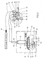
- FIG. 2 shows a hydraulic circuit diagram of a circuit via which the hydraulic top link 12 can be supplied via the directional control valve 18 with pressure medium in order to adjust the top link length.
- the hydraulic top link 12 is practically designed as a hydraulic cylinder whose piston divides the cylinder into a cylinder chamber 38 and an annular space 40.
- a piston rod 42 is executed at its free end portion with a coupling 44 to which the attachment or semi-mounted device is attached.
- circuit is designed as a LS system.
- the pump pressure is always adjusted so that it is above the highest load pressure of the hydraulic consumers by a predetermined pressure difference.
- LS-way valves consist of a pilot-operated proportional valve 44 to which a LS pressure compensator 46 is assigned. Both components are usually integrated in a valve disc of a mobile control block.
- the adjustment of the proportional valve 44 is electro-hydraulic, for example via pressure reducing valves 48 which are adjustable via a proportional solenoid.
- the directional control valve 18 usually has a pressure connection P connected to the hydraulic pump 14, an LS (load pressure) connection LS, a return connection R connected to the tank 16, and two working connections A, B.
- a pumping chute 50 leads from the pressure connection P of the directional control valve disk Input terminal of the pressure compensator 46, which is acted upon in the opening direction by the force of a pressure compensator spring 52 and the load pressure on the upper link 12, wherein this load pressure is tapped via an LS line 54.
- the pressure compensator 46 is acted upon in the direction of a reduction in the opening cross section by the pressure at the outlet of the pressure compensator, which is tapped off via a control channel 56 from an inlet channel 58 connecting the outlet connection of the pressure compensator 46 to an input connection P of the proportional valve 44.
- the proportional valve 44 is biased via a Zentrierfederanssen in a locking position zero, in which the pressure port P, a tank port T and two working ports A, B are shut off.
- the tank connection T is connected to the tank connection T via a drainage channel 59.
- a valve spool of the proportional valve 44 By adjusting a valve spool of the proportional valve 44 in the direction of its positions a, the pressure medium connection between the pressure port P and the working port A and from the working port B to the tank port T is opened.
- the pressure connection P is connected to the working connection flange corresponding to the working connection A with the tank connection T.
- a floating position c is set, in which the two working ports A; B are connected together with the tank connection T, so that the upper link is freely adjustable. In this floating position, the pressure port P is shut off.
- the working port A is connected via a feed line 60 to the working port A of the directional control valve 18 and the working port B of the proportional valve 44 is connected via a return port 62 to the working port B of the directional valve disc 18 of the directional control valve.
- the flow channel 60 can also serve as a return channel 62.
- the load pressure acting on the pressure compensator in the opening direction is tapped via a shuttle valve 64 from the two channels 60, 62, which lie in the pressure medium flow or in the pressure medium return, depending on the control of the proportional valve 44.
- an inlet orifice plate is adjusted, wherein the pressure drop across the inlet orifice plate can be kept constant independently of the load via the pressure compensator 46 - this pressure drop corresponds to the pressure equivalent of the spring 52.
- the two working ports A, B of the valve disc are connected via working lines 66, 68 with the hydraulic top link 12.
- this hydraulic top link 12 is designed with a blocking block 69 with two shut-off valves 70, 72 which are releasable from the respective pressure at the inlet of the other shut-off valve 72, 70.
- the blocking block is placed on the top link 12, so that results in a very compact design.
- the two working lines 66, 68 are connected to the two inputs P, Q of the blocking block 69, the output terminals C, D are connected via supply lines 74, 76 with the annular space 40 and the cylinder space 38.
- the pressure in these pressure chambers 38, 40 is detected in each case via pressure sensors 78, 80 and the effective length of the upper link 12 via a displacement sensor 82.
- the hydraulic connection of the upper link 12 with the tractor can also be done via conventional Schnellkuppelan getting or by solid fittings.
- the individual electronic components such as the electronic control devices, display devices, sensors, pilot valves, etc. are connected to each other via a suitable bus system such as a CAN bus, so that electronic functions with high complexity can be realized.
- a suitable bus system such as a CAN bus
- the proportional valve 44 is adjusted in the direction of its position indicated by a, so that pressure medium via the pressure compensator 46, the controlled inlet orifice (proportional valve 44), the flow channel 60, the working line 66, the blocking block 69 flows to the cylinder chamber 38 , so that the piston of the hydraulic top link 12 is moved to the right and thus its effective length is increased.
- the corresponding displaced from the annular space 40 pressure fluid flows through the supply line 74, the pressure in the flow-controlled shut-off valve 70, the working line 68, the return passage 62, the proportional valve 44 and the drain passage 59 to the tank 16 down.
- the pressures which occur in the pressure chambers 38, 40 are detected by the two sensors 78, 80 and taken into account in a regulation which will be described in more detail below. Accordingly, the stroke of the upper link 12 is detected via the position transducer 82 and fed as an actual signal to the electronic control unit 20 of the upper link control.
- Such a displacement transducer 82 may be embodied, for example, as a magnetostrictive position sensor, which enables a non-contact position measurement after the physical phenomenon of the magnetostriction.
- dargesellten solution is that can be dispensed with in the usual way in the directional control valve 18 integrated mechanical check valves for leak oil-free clamping of the upper link 12, so that in the lines 66, 68, 60, 62 no pressures are clamped.
- the control pressure in the control oil supply line 98 can be switched off, so that an unwanted adjustment of the proportional valve 44 can be prevented.
- the length of the upper link 12 can be adjusted manually to adjust the inclination of the attachment.
- the attachment can be moved path-controlled, each stroke position of the lower link 30 is a setpoint is assigned for the top link length, so that the attachment can be raised, for example, in the steep excavation or parallel excavation.
- the third possibility is to activate the pressure control of the upper link during the electrohydraulic linkage control, so that the relief or load of follower devices of the attachment / semi-trailer device can be regulated.
- the path control and the pressure control can both be activated.
- a length control of the hydraulic top link 12 with a direct setpoint specification is practically not useful by the operator, the above-mentioned manual length adjustment over the control panel is safer than a length control, as for example when releasing the button for actuating the top link - similar to the electro-hydraulic Hoist control - an immediate stop of movement takes place. If the setpoint was set by the driver, the top link would be adjusted in the direction of this setpoint. That for manual length adjustment no length control of the top link is required.
- FIG. 3 shows an enlarged view of the control panel 36, which is arranged within reach of the operator in the tractor cab 26.
- a display with adjustment potentiometers and buttons may be used.
- This control panel 36 has essentially three controls: two buttons 86, 87 for manually adjusting the length of the upper link 12, wherein the upper link length is increased via the button 37 marked with + and the top link length is shortened via the button 36 marked with.
- the control panel 36 further has actuators, such as a knob of a potentiometer 88, for activating the length control of the upper link 12 so that there is correspondingly a path control of the linkage.
- actuators such as a knob of a potentiometer 88
- the top link 12 is shortened during the lifting of the hoist 2, so that the steepness of the excavation is increased.
- the upper link 12 is extended, so that the attachment can be kept parallel to the ground depending on the setting (parallel excavation).
- potentiometer 90 With a further potentiometer 90, the pressure control for the upper link 12 is activated accordingly, wherein by adjusting the potentiometer 90 to the left in FIG. 3 is pulled with the top link 12 on the attachment while through a Twist to the right with the top link is pressed. As explained in more detail below, both regulations can be activated.
- the manual adjustment of the top link length can also be made via the arranged on the rear or on the fenders of the tractor 1 button 28, where pairs of buttons of the electro-hydraulic hitch control and other pairs of buttons are assigned to the top link length adjustment.
- the function or effect of these buttons corresponds exactly to the buttons 86, 87 in FIG. 3 ,
- the + key 87 is actuated, so that the upper link 12 is extended as long as the key is pressed.
- the button 86 is correspondingly shortened the top link, wherein when you release the respective key 86, 87 immediately stops the top link movement.
- the volumetric flow setpoint is slowly increased to the proportional valve 44 in a ramp, for example, an increase to about 20 l / min within 4 sec. This slow up-regulation of the volumetric flow setpoint enables very accurate positioning. In principle, the operator of this ramp-like start-up of the volume flow from the operation of conventional rear and front hoists known so that the top link adjustment can be done safely and intuitively.
- buttons 86, 87 or even buttons of the EHR hoist control are operated simultaneously, no actuating signal is considered correct - there is no adjustment of the hoist. This adjustment can only be done by pressing a single button 86, 87 again.
- the implement can be performed when lifting along a certain trajectory. These trajectories are essentially the "steep excavation” and the "parallel excavation".
- the degree of steepness ie the amount by which the top link is to shorten when changing the bearing of the lower link 30, is set on the potentiometer 88.
- the upper link 12 is correspondingly extended during the lifting, so that the attachment 32 is mounted flatter on the tractor 1, that is to say in the case in which no upper link extension takes place.
- the extent to which the device is flatter at the respective hoist height is adjusted by turning the potentiometer 88 to the right.
- the device 32 remains parallel to the ground when the potentiometer 88 is properly adjusted.
- top link pressure control set via the potentiometer 90
- an axle load change on the tractor and on the attachment 32 can take place.
- the aim of this pressure control is a fuel saving, since, for example, by a Schuachslasterhöhung less slippage and thus a higher travel speed and, accordingly, a higher area performance, i. a larger machined surface per unit time is feasible and thus consumed correspondingly less fuel.
- the top-link pressure control it is possible to set a tensile force or a compressive force acting on the implement 32, the height of the force being set via the potentiometer 90. That when the potentiometer 90 is moved to its "OFF" position, a pressure of 0 bar is not regulated, but the pressure control is switched off.
- the hoist is manually moved to a predetermined basic position, which may depend on the type of attachment / Aufsattel advocatess.
- the hoist 2 is lowered by manual control of the lifting cylinder 8 until a working position is reached.
- the length of the top link is then manually set by the operator via the buttons 86, 87 and after setting the reference length of the top link and the hoist position (with respect to the tractor 1) automatically stored as a reference value pair in the memory of the controller 20.
- the operator does not have to make any manual presets.
- the hoist 2 can be actuated according to the various operating strategies. Basically, these operating strategies provide that the top link in the automatic functions depending on the setting of the potentiometer 88, 90 depending is adjusted from the reference length when the electrohydraulic hoist control (EHR) is activated. As already stated, the position of the lower links 30 with respect to the tractor 1 is set via the EHR. Depending on the selected control strategy, the length of the top link (top link path control) or the pressure on the hydraulic top link 12 can be controlled via the top link automatic.
- EHR electrohydraulic hoist control
- the top link 12 changes its length when the hoist 2 is actuated via the EHR.
- the potentiometer 88 depending on the distance of the current position of the lower link 30 is changed to the stored with the reference length position of the length command value of the upper link 12, wherein the size of the strignsollwert Sung, based on the manually set reference length and reference position of the hoist via the potentiometer 88 is specified. That in the so-called top link path control is carried out a position control of the lower link 30 and a length control of the upper link 12 in dependence on the Hubwerkslage and the set via the potentiometer 88 characteristic (rough excavation / Parallelaushub).
- the top link length is adjusted to set a predetermined pressure setpoint or a desired pressure difference in the pressure chambers 38, 40 of the top link 12.
- This pressure control operates only during the regular operation of the EHR, i. Position, traction or mixed control of the lower links 30.
- the pressure control is interrupted immediately when the EHR is switched off, the hoist is in the transport position or the hoist is locked. An interruption also occurs when the external buttons are pressed and in the case of an error message in the system control.
- the adjustment of the pressure control, the axle load distribution on the tractor and the device can be influenced to optimize the work or the fuel consumption.
- the path control When pressure control is activated, the path control is automatically activated, as otherwise it may happen that the implement is not excavated sufficiently during excavation or that it is not pulled in properly when pulling it in. The path control then works especially when lifting without changing the top link length, so that no steep or parallel excavation takes place.
- the top link 12 is initially set to the reference length via the path control.
- the path control is then released from the pressure control, the adjusted pressure being preset via the potentiometer 90.
- the web control and the pressure control can be activated in parallel by adjusting the potentiometer 88, 90; Also in this case, the top link length is set to the reference length and then replaced the web control of the pressure control. This detachment takes place in a several seconds continuous transition. For a plow 32 this is necessary, for example, since the rear plowshares must first move in (long top link) in order to be able to absorb a force from the ground downwards. Only then can you pull back on the top link (short top link 12) in order to be able to direct these shear forces to the rear axle of the tractor 1.
- the operational safety in the operation of the hoist 8 can be significantly increased by the measures described below, and it is difficult in many cases, to separate the working functions of the safety functions described below.
- the potentiometer 88 may well be moved out of its "OFF" position - according to the safety function, it is ensured that the upper link, if necessary, does not move in a regulated manner.
- the EHR button 28 are actuated, in addition to the adjustment of the lower link 30 also the provision of the upper link 12 from Steilaushub or Parallelaushub in the previously manually set reference position of the upper link 12.
- This is a one-time deferral , which is preferably only when pressing the EHR-lowering button.
- lifting no more track control and the top link length remains unchanged. This is necessary, for example, when a steeply lifted plow 32 remains steep when lowered for dismounting. Then a complex manual double adjustment of lower link 30 and upper link 12 would be necessary. Instead, according to the described safety strategy, the top link 12 moves rapidly into its reference length, while the hoist 2 gradually decreases.
- the top link length is not changed. It can not be switched without re-unlocking the EHR in the pressure control or path control of the upper link 12.
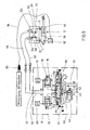
- FIG. 5 another embodiment of a top link automatic is explained.
- the basic construction of this embodiment corresponds to that of FIG. 2 , so that only the essential differences are explained here.
- the adjustment of the hydraulic top link 12 via a directional control valve section 18 of the mobile control block which has a proportional valve 44 with upstream LS-pressure compensator 46.
- the LS-pressure compensator by the spring 52 and the load pressure on the upper link 12 in the opening direction and the pressure in the inlet channel 58, that is applied upstream of the metering orifice in the closing direction.
- the proportional valve 44 are two sink modules 92, 94 assigned, each serving in their spring-biased home position as a pilot check valve for leak oil-free clamping of the upper link 12 and control in a control position flowing back from the upper link 12 pressure medium flow in the sense of a flow control.
- Each drain module 92, 94 is acted upon by a spring 96 and by the pressure in the flow channels 60, 62 respectively in the direction of the check position and a pilot or control pressure in a control oil supply line 98 in the direction of its throttle position.
- the pressure in the pressure medium flow path between the sink modules 92, 94 and the working ports A, B is detected by pressure sensors 78, 80.
- the structure of the proportional valve 44, the sink modules 92, 94 and the LS-pressure compensator 46 is known in principle from applications for EHR, as shown in the DE 10 2005 005 314 A1 are described so that in the present application only the essential elements for understanding the invention are described.
- the directional control valve 44 has a pressure port P, a tank port T and two output ports A, B, to which the channels 62, 64 are connected.
- the proportional valve 44 is further designed with two control terminals X1 and X2, via which the control pressure in the control oil supply line 98 can be tapped.
- the pressure acting on the drain modules 92, 94 in the throttle direction is tapped via control terminals XA, XB.
- the ports A, B, P, T, XA, XB, X1 and X2 are shut off and an LS port is connected to the drain passage 59.
- the proportional valve When energizing the in FIG. 5 left pilot valve 48, the proportional valve is adjusted in the direction of its marked with a positions and the pressure port P to the working port B and the working port A connected to the tank port T. Further, then the control oil supply line 98 is connected to the terminal XA, so that the drain module 92 is acted upon by the control oil pressure in the throttle direction. The two connections XB and X2 are blocked.
- the pressure port P to the working port A and the working port B to the tank port T and the control port X2 are connected to the control output port XB accordingly.
- the connections XA and X1 are blocked.
- the drain module 94 is then actuated by the control pressure in the Control oil supply line 98 applied in the direction of its throttle position to allow a flow control.
- the proportional valve 44 is adjusted in the direction of the positions indicated by c, the upper link 12 is brought into its floating position.
- other directional valves can be used, eg from Danfoss, PVG, Hasco. Here only two check valves are used.
- a blocking block 69 is placed on the top link 12, the terminals P, Q are connected to the working lines 66, 68. As in FIG. 5 indicated, these working lines 66, 68 can be connected via hose couplings to the tractor hydraulics.
- the blocking block 69 in turn has two unlockable by the pressure in the other line blocking valves 70, 72, which allow a flow of pressure medium from the terminals P, Q to the associated output terminals C, D of the blocking block 69, so that correspondingly the pressure chambers 38, 40 with the Pump or the tank are connected.
- the stroke of the upper link 12 is in turn detected by a displacement sensor 82.
- the blocking block 69 is designed with two bypass lines 100, 102, over which in the area between the terminals C, P and D, Q, the respective shut-off valve 70, 72 is bypassed, so that said connections via the bypass lines 100, 102nd and throttles 104, 106 disposed therein are directly connected.
- the cross section is designed so that the control oil losses are comparatively low.
- shut-off must be made via the directional control valve 18 or other additional check valves.
- the two sink modules 92, 94 required.
- the shut-off is leak-free through the two check valves 70, 72 of the locking block 69, so that the upper link 12 are clamped without leakage.
- the hoist is manually returned to its Hubtechniksarbeitswolf or other desired position and set the top link length manually to the reference length.
- a pressure gradient is calculated from the measured pressures in the pressure chambers 38, 40 and the current load direction (pulling load / pressing load), in which the pressure change at the upper link 12 in dependence is determined by the change in length. From this pressure gradient can then be calculated that upper link length at which sets the desired target pressure.
- the top link is then adjusted to the setpoint calculated in this way after the length control described above.
- the pressure in the pressure chambers 38, 40 adjusts itself within a very short time via the bypass lines 100, 102 also in the line sections 66, 68 and 60, 62, so that can be recorded via the integrated pressure in the directional control valve 18 unadulterated pressure signals.
- a predetermined pressure equalization time about 1 sec
- the pressure in the pressure chambers 38, 40 is again measured and a new pressure gradient is calculated from the previously made change in length and the resulting pressure change, which is averaged with strong weighting with the previously calculated pressure gradient.
- a new top link length is then calculated at which the desired target pressure is set. This cycle is repeated until the desired set pressure at the top link is established. In this case, a dead band of about +/- 5 bar is allowed as a tolerance.
- a hoist and a method for driving a hoist This has a hydraulically adjustable upper link to which a locking block is attached and a pressure control circuit with pressure sensors for detecting the pressure on the upper link.
Landscapes
- Life Sciences & Earth Sciences (AREA)
- Engineering & Computer Science (AREA)
- Mechanical Engineering (AREA)
- Soil Sciences (AREA)
- Environmental Sciences (AREA)
- Fluid-Pressure Circuits (AREA)
- Lifting Devices For Agricultural Implements (AREA)
Applications Claiming Priority (2)
| Application Number | Priority Date | Filing Date | Title |
|---|---|---|---|
| DE102007033978 | 2007-07-19 | ||
| DE102007040344A DE102007040344A1 (de) | 2007-07-19 | 2007-08-27 | Hubwerk und Verfahren zum Ansteuern eines derartigen Hubwerks |
Publications (2)
| Publication Number | Publication Date |
|---|---|
| EP2016818A1 true EP2016818A1 (fr) | 2009-01-21 |
| EP2016818B1 EP2016818B1 (fr) | 2016-05-04 |
Family
ID=40149135
Family Applications (1)
| Application Number | Title | Priority Date | Filing Date |
|---|---|---|---|
| EP08012083.5A Not-in-force EP2016818B1 (fr) | 2007-07-19 | 2008-07-04 | Dispositif de levage et procédé de commande d'un tel dispositif de levage |
Country Status (2)
| Country | Link |
|---|---|
| EP (1) | EP2016818B1 (fr) |
| DE (1) | DE102007040344A1 (fr) |
Cited By (5)
| Publication number | Priority date | Publication date | Assignee | Title |
|---|---|---|---|---|
| WO2016169829A1 (fr) * | 2015-04-24 | 2016-10-27 | Robert Bosch Gmbh | Ensemble de levage électrohydraulique, procédé destiné à un tel ensemble et machine de traction |
| DE102013222150B4 (de) | 2013-10-31 | 2018-03-01 | Schaeffler Technologies AG & Co. KG | Anbaugerät oder Landwirtschaftsfahrzeug mit einem Überwachungsmodul |
| EP3599382A1 (fr) * | 2018-07-23 | 2020-01-29 | Joab Försäljnings Ab | Système hydraulique et procédé de commande de la vitesse et de la pression d'un vérin hydraulique |
| EP3932158A1 (fr) * | 2020-07-03 | 2022-01-05 | CLAAS Tractor S.A.S. | Tracteur et procédé de fonctionnement d'un tracteur |
| US11221636B2 (en) | 2018-02-28 | 2022-01-11 | Deere & Company | Method for controlling a hydraulic top link of a three-point linkage |
Citations (7)
| Publication number | Priority date | Publication date | Assignee | Title |
|---|---|---|---|---|
| EP1403102A1 (fr) * | 2002-09-27 | 2004-03-31 | CNH Italia S.p.A. | Attelage pour tracteurs et circuit hydraulique associé |
| DE10350651B3 (de) | 2003-10-29 | 2005-05-25 | Gkn Walterscheid Gmbh | Verfahren zur Längeneinstellung eines Oberlenkers |
| DE102005005316A1 (de) | 2004-02-17 | 2005-08-25 | Denso Corp., Kariya | Von einem Motor angesteuertes Servolenkungssystem |
| DE102004033315A1 (de) | 2004-07-09 | 2006-02-09 | Bosch Rexroth Aktiengesellschaft | Hubwerksventilanordnung |
| DE102005005314A1 (de) | 2004-12-20 | 2006-06-22 | Bosch Rexroth Aktiengesellschaft | Ventilanordnung und Verfahren zur Ansteuerung eines doppeltwirkenden Verbrauchers |
| AT8986U1 (de) * | 2005-10-28 | 2007-03-15 | Hoerbiger Automatisierungstech | Hydraulische druckversorgungseinheit, sowie elektrohydraulische arbeitseinheit und spannsystem mit einer derartigen druckversorgungseinheit |
| DE102006038801A1 (de) * | 2006-08-18 | 2008-02-21 | Amazonen-Werke H. Dreyer Gmbh & Co. Kg | Hydraulische Betätigungseinrichtung |
-
2007
- 2007-08-27 DE DE102007040344A patent/DE102007040344A1/de not_active Withdrawn
-
2008
- 2008-07-04 EP EP08012083.5A patent/EP2016818B1/fr not_active Not-in-force
Patent Citations (8)
| Publication number | Priority date | Publication date | Assignee | Title |
|---|---|---|---|---|
| EP1403102A1 (fr) * | 2002-09-27 | 2004-03-31 | CNH Italia S.p.A. | Attelage pour tracteurs et circuit hydraulique associé |
| DE60303482T2 (de) | 2002-09-27 | 2006-07-20 | Cnh Italia S.P.A. | Dreipunktkupplung für Traktoren und zugehörige hydraulische Steuerung |
| DE10350651B3 (de) | 2003-10-29 | 2005-05-25 | Gkn Walterscheid Gmbh | Verfahren zur Längeneinstellung eines Oberlenkers |
| DE102005005316A1 (de) | 2004-02-17 | 2005-08-25 | Denso Corp., Kariya | Von einem Motor angesteuertes Servolenkungssystem |
| DE102004033315A1 (de) | 2004-07-09 | 2006-02-09 | Bosch Rexroth Aktiengesellschaft | Hubwerksventilanordnung |
| DE102005005314A1 (de) | 2004-12-20 | 2006-06-22 | Bosch Rexroth Aktiengesellschaft | Ventilanordnung und Verfahren zur Ansteuerung eines doppeltwirkenden Verbrauchers |
| AT8986U1 (de) * | 2005-10-28 | 2007-03-15 | Hoerbiger Automatisierungstech | Hydraulische druckversorgungseinheit, sowie elektrohydraulische arbeitseinheit und spannsystem mit einer derartigen druckversorgungseinheit |
| DE102006038801A1 (de) * | 2006-08-18 | 2008-02-21 | Amazonen-Werke H. Dreyer Gmbh & Co. Kg | Hydraulische Betätigungseinrichtung |
Cited By (7)
| Publication number | Priority date | Publication date | Assignee | Title |
|---|---|---|---|---|
| DE102013222150B4 (de) | 2013-10-31 | 2018-03-01 | Schaeffler Technologies AG & Co. KG | Anbaugerät oder Landwirtschaftsfahrzeug mit einem Überwachungsmodul |
| WO2016169829A1 (fr) * | 2015-04-24 | 2016-10-27 | Robert Bosch Gmbh | Ensemble de levage électrohydraulique, procédé destiné à un tel ensemble et machine de traction |
| US11221636B2 (en) | 2018-02-28 | 2022-01-11 | Deere & Company | Method for controlling a hydraulic top link of a three-point linkage |
| EP3599382A1 (fr) * | 2018-07-23 | 2020-01-29 | Joab Försäljnings Ab | Système hydraulique et procédé de commande de la vitesse et de la pression d'un vérin hydraulique |
| US11668296B2 (en) | 2018-07-23 | 2023-06-06 | Joab Forsaljnings Ab | Hydraulic system and method for controlling the speed and pressure of a hydraulic cylinder |
| EP3932158A1 (fr) * | 2020-07-03 | 2022-01-05 | CLAAS Tractor S.A.S. | Tracteur et procédé de fonctionnement d'un tracteur |
| US12114586B2 (en) | 2020-07-03 | 2024-10-15 | CLAAS Tractor S.A.S | Tractor and method for operating a tractor |
Also Published As
| Publication number | Publication date |
|---|---|
| DE102007040344A1 (de) | 2009-01-22 |
| EP2016818B1 (fr) | 2016-05-04 |
Similar Documents
| Publication | Publication Date | Title |
|---|---|---|
| EP2031256B1 (fr) | Dispositif de levage et procédé de commande d'un dispositif de levage | |
| EP1766146B2 (fr) | Systeme de soupapes de mecanisme de levage | |
| EP2524585B1 (fr) | Dispositif de levage | |
| EP1915538B1 (fr) | Montage pour commander un cylindre d'entrainement hydraulique a double effet | |
| EP3584450B1 (fr) | Engin de travail utilisable dans l'agriculture ou les travaux publics avec une commande de signal de charge d'une section hydraulique de travail d'un appareil auxiliaire | |
| EP2449267B1 (fr) | Dispositif de soupape | |
| DE102004029409A1 (de) | Druckmittelbetätigte Stelleinrichtung, insbesondere für eine Fahrzeuglenkvorrichtung | |
| EP1907706B1 (fr) | Circuit hydraulique, en particulier pour l'entraînement de mâts de distributeurs de béton | |
| DE10138389A1 (de) | Elektrohydraulische Einrichtung zur Steuerung eines doppelt wirkenden Motors | |
| EP2016818B1 (fr) | Dispositif de levage et procédé de commande d'un tel dispositif de levage | |
| EP1743981A1 (fr) | Agencement hydraulique | |
| EP2016817B1 (fr) | Procédé de commande d'un dispositif de levage et dispositif de levage | |
| EP2404493B1 (fr) | Dispositif de levage | |
| EP3436705B1 (fr) | Dispositif de commande | |
| DE19548943B4 (de) | Ventilanordnung | |
| EP4275465B1 (fr) | Dispositif de réglage hydraulique | |
| AT502034B1 (de) | Hydraulische steuerung für einen drehpflug | |
| EP1766246B1 (fr) | Procede de commande d'un systeme a vannes pour dispositif de levage | |
| EP3236085B1 (fr) | Vanne amplificatrice pour un circuit hydraulique de travail conçu comme circuit à centre fermé d'un engin de travail utilisable dans l'agriculture ou les travaux publics | |
| EP2639104B1 (fr) | Commande hydraulique d'un vérin de basculement facilement actionnable | |
| DE19719745B4 (de) | Druckschaltventilanordnung mit Überlastsicherungsfunktion für einen hydraulischen Verbraucher | |
| EP3002462A1 (fr) | Systeme de commande hydraulique | |
| EP1622443A1 (fr) | Dispositif et procede de commande du systeme de levage d'un vehicule agricole | |
| EP3985264A1 (fr) | Agencement et procédé de commande d'un mécanisme de levage | |
| DE4216456A1 (de) | Servo-hydraulisches Hubwerksregelsystem |
Legal Events
| Date | Code | Title | Description |
|---|---|---|---|
| PUAI | Public reference made under article 153(3) epc to a published international application that has entered the european phase |
Free format text: ORIGINAL CODE: 0009012 |
|
| AK | Designated contracting states |
Kind code of ref document: A1 Designated state(s): AT BE BG CH CY CZ DE DK EE ES FI FR GB GR HR HU IE IS IT LI LT LU LV MC MT NL NO PL PT RO SE SI SK TR |
|
| AX | Request for extension of the european patent |
Extension state: AL BA MK RS |
|
| 17P | Request for examination filed |
Effective date: 20090721 |
|
| 17Q | First examination report despatched |
Effective date: 20090814 |
|
| AKX | Designation fees paid |
Designated state(s): AT BE BG CH CY CZ DE DK EE ES FI FR GB GR HR HU IE IS IT LI LT LU LV MC MT NL NO PL PT RO SE SI SK TR |
|
| GRAP | Despatch of communication of intention to grant a patent |
Free format text: ORIGINAL CODE: EPIDOSNIGR1 |
|
| INTG | Intention to grant announced |
Effective date: 20160127 |
|
| GRAS | Grant fee paid |
Free format text: ORIGINAL CODE: EPIDOSNIGR3 |
|
| GRAA | (expected) grant |
Free format text: ORIGINAL CODE: 0009210 |
|
| AK | Designated contracting states |
Kind code of ref document: B1 Designated state(s): AT BE BG CH CY CZ DE DK EE ES FI FR GB GR HR HU IE IS IT LI LT LU LV MC MT NL NO PL PT RO SE SI SK TR |
|
| REG | Reference to a national code |
Ref country code: GB Ref legal event code: FG4D Free format text: NOT ENGLISH |
|
| REG | Reference to a national code |
Ref country code: CH Ref legal event code: EP |
|
| REG | Reference to a national code |
Ref country code: AT Ref legal event code: REF Ref document number: 796019 Country of ref document: AT Kind code of ref document: T Effective date: 20160515 |
|
| REG | Reference to a national code |
Ref country code: IE Ref legal event code: FG4D Free format text: LANGUAGE OF EP DOCUMENT: GERMAN |
|
| REG | Reference to a national code |
Ref country code: DE Ref legal event code: R096 Ref document number: 502008014149 Country of ref document: DE |
|
| REG | Reference to a national code |
Ref country code: NL Ref legal event code: MP Effective date: 20160504 |
|
| REG | Reference to a national code |
Ref country code: LT Ref legal event code: MG4D |
|
| PG25 | Lapsed in a contracting state [announced via postgrant information from national office to epo] |
Ref country code: NL Free format text: LAPSE BECAUSE OF FAILURE TO SUBMIT A TRANSLATION OF THE DESCRIPTION OR TO PAY THE FEE WITHIN THE PRESCRIBED TIME-LIMIT Effective date: 20160504 Ref country code: LT Free format text: LAPSE BECAUSE OF FAILURE TO SUBMIT A TRANSLATION OF THE DESCRIPTION OR TO PAY THE FEE WITHIN THE PRESCRIBED TIME-LIMIT Effective date: 20160504 Ref country code: NO Free format text: LAPSE BECAUSE OF FAILURE TO SUBMIT A TRANSLATION OF THE DESCRIPTION OR TO PAY THE FEE WITHIN THE PRESCRIBED TIME-LIMIT Effective date: 20160804 Ref country code: FI Free format text: LAPSE BECAUSE OF FAILURE TO SUBMIT A TRANSLATION OF THE DESCRIPTION OR TO PAY THE FEE WITHIN THE PRESCRIBED TIME-LIMIT Effective date: 20160504 |
|
| PG25 | Lapsed in a contracting state [announced via postgrant information from national office to epo] |
Ref country code: GR Free format text: LAPSE BECAUSE OF FAILURE TO SUBMIT A TRANSLATION OF THE DESCRIPTION OR TO PAY THE FEE WITHIN THE PRESCRIBED TIME-LIMIT Effective date: 20160805 Ref country code: HR Free format text: LAPSE BECAUSE OF FAILURE TO SUBMIT A TRANSLATION OF THE DESCRIPTION OR TO PAY THE FEE WITHIN THE PRESCRIBED TIME-LIMIT Effective date: 20160504 Ref country code: SE Free format text: LAPSE BECAUSE OF FAILURE TO SUBMIT A TRANSLATION OF THE DESCRIPTION OR TO PAY THE FEE WITHIN THE PRESCRIBED TIME-LIMIT Effective date: 20160504 Ref country code: PT Free format text: LAPSE BECAUSE OF FAILURE TO SUBMIT A TRANSLATION OF THE DESCRIPTION OR TO PAY THE FEE WITHIN THE PRESCRIBED TIME-LIMIT Effective date: 20160905 Ref country code: ES Free format text: LAPSE BECAUSE OF FAILURE TO SUBMIT A TRANSLATION OF THE DESCRIPTION OR TO PAY THE FEE WITHIN THE PRESCRIBED TIME-LIMIT Effective date: 20160504 Ref country code: LV Free format text: LAPSE BECAUSE OF FAILURE TO SUBMIT A TRANSLATION OF THE DESCRIPTION OR TO PAY THE FEE WITHIN THE PRESCRIBED TIME-LIMIT Effective date: 20160504 |
|
| PG25 | Lapsed in a contracting state [announced via postgrant information from national office to epo] |
Ref country code: IT Free format text: LAPSE BECAUSE OF FAILURE TO SUBMIT A TRANSLATION OF THE DESCRIPTION OR TO PAY THE FEE WITHIN THE PRESCRIBED TIME-LIMIT Effective date: 20160504 Ref country code: BE Free format text: LAPSE BECAUSE OF NON-PAYMENT OF DUE FEES Effective date: 20160731 |
|
| PG25 | Lapsed in a contracting state [announced via postgrant information from national office to epo] |
Ref country code: SK Free format text: LAPSE BECAUSE OF FAILURE TO SUBMIT A TRANSLATION OF THE DESCRIPTION OR TO PAY THE FEE WITHIN THE PRESCRIBED TIME-LIMIT Effective date: 20160504 Ref country code: DK Free format text: LAPSE BECAUSE OF FAILURE TO SUBMIT A TRANSLATION OF THE DESCRIPTION OR TO PAY THE FEE WITHIN THE PRESCRIBED TIME-LIMIT Effective date: 20160504 Ref country code: EE Free format text: LAPSE BECAUSE OF FAILURE TO SUBMIT A TRANSLATION OF THE DESCRIPTION OR TO PAY THE FEE WITHIN THE PRESCRIBED TIME-LIMIT Effective date: 20160504 Ref country code: CZ Free format text: LAPSE BECAUSE OF FAILURE TO SUBMIT A TRANSLATION OF THE DESCRIPTION OR TO PAY THE FEE WITHIN THE PRESCRIBED TIME-LIMIT Effective date: 20160504 Ref country code: RO Free format text: LAPSE BECAUSE OF FAILURE TO SUBMIT A TRANSLATION OF THE DESCRIPTION OR TO PAY THE FEE WITHIN THE PRESCRIBED TIME-LIMIT Effective date: 20160504 |
|
| REG | Reference to a national code |
Ref country code: DE Ref legal event code: R097 Ref document number: 502008014149 Country of ref document: DE |
|
| PG25 | Lapsed in a contracting state [announced via postgrant information from national office to epo] |
Ref country code: PL Free format text: LAPSE BECAUSE OF FAILURE TO SUBMIT A TRANSLATION OF THE DESCRIPTION OR TO PAY THE FEE WITHIN THE PRESCRIBED TIME-LIMIT Effective date: 20160504 |
|
| REG | Reference to a national code |
Ref country code: CH Ref legal event code: PL |
|
| PLBE | No opposition filed within time limit |
Free format text: ORIGINAL CODE: 0009261 |
|
| STAA | Information on the status of an ep patent application or granted ep patent |
Free format text: STATUS: NO OPPOSITION FILED WITHIN TIME LIMIT |
|
| PG25 | Lapsed in a contracting state [announced via postgrant information from national office to epo] |
Ref country code: MC Free format text: LAPSE BECAUSE OF FAILURE TO SUBMIT A TRANSLATION OF THE DESCRIPTION OR TO PAY THE FEE WITHIN THE PRESCRIBED TIME-LIMIT Effective date: 20160504 |
|
| 26N | No opposition filed |
Effective date: 20170207 |
|
| GBPC | Gb: european patent ceased through non-payment of renewal fee |
Effective date: 20160804 |
|
| PG25 | Lapsed in a contracting state [announced via postgrant information from national office to epo] |
Ref country code: FR Free format text: LAPSE BECAUSE OF NON-PAYMENT OF DUE FEES Effective date: 20160801 Ref country code: LI Free format text: LAPSE BECAUSE OF NON-PAYMENT OF DUE FEES Effective date: 20160731 Ref country code: CH Free format text: LAPSE BECAUSE OF NON-PAYMENT OF DUE FEES Effective date: 20160731 |
|
| REG | Reference to a national code |
Ref country code: FR Ref legal event code: ST Effective date: 20170331 |
|
| REG | Reference to a national code |
Ref country code: IE Ref legal event code: MM4A |
|
| PG25 | Lapsed in a contracting state [announced via postgrant information from national office to epo] |
Ref country code: SI Free format text: LAPSE BECAUSE OF FAILURE TO SUBMIT A TRANSLATION OF THE DESCRIPTION OR TO PAY THE FEE WITHIN THE PRESCRIBED TIME-LIMIT Effective date: 20160504 |
|
| PG25 | Lapsed in a contracting state [announced via postgrant information from national office to epo] |
Ref country code: IE Free format text: LAPSE BECAUSE OF NON-PAYMENT OF DUE FEES Effective date: 20160704 Ref country code: GB Free format text: LAPSE BECAUSE OF NON-PAYMENT OF DUE FEES Effective date: 20160804 |
|
| PG25 | Lapsed in a contracting state [announced via postgrant information from national office to epo] |
Ref country code: LU Free format text: LAPSE BECAUSE OF NON-PAYMENT OF DUE FEES Effective date: 20160704 |
|
| REG | Reference to a national code |
Ref country code: AT Ref legal event code: MM01 Ref document number: 796019 Country of ref document: AT Kind code of ref document: T Effective date: 20160704 |
|
| PG25 | Lapsed in a contracting state [announced via postgrant information from national office to epo] |
Ref country code: AT Free format text: LAPSE BECAUSE OF NON-PAYMENT OF DUE FEES Effective date: 20160704 |
|
| PG25 | Lapsed in a contracting state [announced via postgrant information from national office to epo] |
Ref country code: CY Free format text: LAPSE BECAUSE OF FAILURE TO SUBMIT A TRANSLATION OF THE DESCRIPTION OR TO PAY THE FEE WITHIN THE PRESCRIBED TIME-LIMIT Effective date: 20160504 Ref country code: HU Free format text: LAPSE BECAUSE OF FAILURE TO SUBMIT A TRANSLATION OF THE DESCRIPTION OR TO PAY THE FEE WITHIN THE PRESCRIBED TIME-LIMIT; INVALID AB INITIO Effective date: 20080704 |
|
| PG25 | Lapsed in a contracting state [announced via postgrant information from national office to epo] |
Ref country code: TR Free format text: LAPSE BECAUSE OF FAILURE TO SUBMIT A TRANSLATION OF THE DESCRIPTION OR TO PAY THE FEE WITHIN THE PRESCRIBED TIME-LIMIT Effective date: 20160504 Ref country code: MT Free format text: LAPSE BECAUSE OF FAILURE TO SUBMIT A TRANSLATION OF THE DESCRIPTION OR TO PAY THE FEE WITHIN THE PRESCRIBED TIME-LIMIT Effective date: 20160504 Ref country code: IS Free format text: LAPSE BECAUSE OF FAILURE TO SUBMIT A TRANSLATION OF THE DESCRIPTION OR TO PAY THE FEE WITHIN THE PRESCRIBED TIME-LIMIT Effective date: 20160504 |
|
| PG25 | Lapsed in a contracting state [announced via postgrant information from national office to epo] |
Ref country code: BG Free format text: LAPSE BECAUSE OF FAILURE TO SUBMIT A TRANSLATION OF THE DESCRIPTION OR TO PAY THE FEE WITHIN THE PRESCRIBED TIME-LIMIT Effective date: 20160504 |
|
| PGFP | Annual fee paid to national office [announced via postgrant information from national office to epo] |
Ref country code: DE Payment date: 20180928 Year of fee payment: 11 |
|
| REG | Reference to a national code |
Ref country code: DE Ref legal event code: R119 Ref document number: 502008014149 Country of ref document: DE |
|
| PG25 | Lapsed in a contracting state [announced via postgrant information from national office to epo] |
Ref country code: DE Free format text: LAPSE BECAUSE OF NON-PAYMENT OF DUE FEES Effective date: 20200201 |