EP2016882A2 - Saugbürste für einen Staubsauger - Google Patents
Saugbürste für einen Staubsauger Download PDFInfo
- Publication number
- EP2016882A2 EP2016882A2 EP08103951A EP08103951A EP2016882A2 EP 2016882 A2 EP2016882 A2 EP 2016882A2 EP 08103951 A EP08103951 A EP 08103951A EP 08103951 A EP08103951 A EP 08103951A EP 2016882 A2 EP2016882 A2 EP 2016882A2
- Authority
- EP
- European Patent Office
- Prior art keywords
- main body
- brush
- brush main
- rib
- suction
- Prior art date
- Legal status (The legal status is an assumption and is not a legal conclusion. Google has not performed a legal analysis and makes no representation as to the accuracy of the status listed.)
- Granted
Links
Images


Classifications
-
- A—HUMAN NECESSITIES
- A47—FURNITURE; DOMESTIC ARTICLES OR APPLIANCES; COFFEE MILLS; SPICE MILLS; SUCTION CLEANERS IN GENERAL
- A47L—DOMESTIC WASHING OR CLEANING; SUCTION CLEANERS IN GENERAL
- A47L9/00—Details or accessories of suction cleaners, e.g. mechanical means for controlling the suction or for effecting pulsating action; Storing devices specially adapted to suction cleaners or parts thereof; Carrying-vehicles specially adapted for suction cleaners
- A47L9/02—Nozzles
- A47L9/06—Nozzles with fixed, e.g. adjustably fixed brushes or the like
-
- A—HUMAN NECESSITIES
- A47—FURNITURE; DOMESTIC ARTICLES OR APPLIANCES; COFFEE MILLS; SPICE MILLS; SUCTION CLEANERS IN GENERAL
- A47L—DOMESTIC WASHING OR CLEANING; SUCTION CLEANERS IN GENERAL
- A47L9/00—Details or accessories of suction cleaners, e.g. mechanical means for controlling the suction or for effecting pulsating action; Storing devices specially adapted to suction cleaners or parts thereof; Carrying-vehicles specially adapted for suction cleaners
- A47L9/02—Nozzles
- A47L9/04—Nozzles with driven brushes or agitators
- A47L9/0427—Gearing or transmission means therefor
- A47L9/0433—Toothed gearings
-
- A—HUMAN NECESSITIES
- A47—FURNITURE; DOMESTIC ARTICLES OR APPLIANCES; COFFEE MILLS; SPICE MILLS; SUCTION CLEANERS IN GENERAL
- A47L—DOMESTIC WASHING OR CLEANING; SUCTION CLEANERS IN GENERAL
- A47L9/00—Details or accessories of suction cleaners, e.g. mechanical means for controlling the suction or for effecting pulsating action; Storing devices specially adapted to suction cleaners or parts thereof; Carrying-vehicles specially adapted for suction cleaners
- A47L9/02—Nozzles
-
- A—HUMAN NECESSITIES
- A47—FURNITURE; DOMESTIC ARTICLES OR APPLIANCES; COFFEE MILLS; SPICE MILLS; SUCTION CLEANERS IN GENERAL
- A47L—DOMESTIC WASHING OR CLEANING; SUCTION CLEANERS IN GENERAL
- A47L9/00—Details or accessories of suction cleaners, e.g. mechanical means for controlling the suction or for effecting pulsating action; Storing devices specially adapted to suction cleaners or parts thereof; Carrying-vehicles specially adapted for suction cleaners
- A47L9/02—Nozzles
- A47L9/04—Nozzles with driven brushes or agitators
- A47L9/0405—Driving means for the brushes or agitators
- A47L9/0422—Driving means for the brushes or agitators driven by the rotation of the supporting wheels on which the nozzle travels over the floor
-
- A—HUMAN NECESSITIES
- A47—FURNITURE; DOMESTIC ARTICLES OR APPLIANCES; COFFEE MILLS; SPICE MILLS; SUCTION CLEANERS IN GENERAL
- A47L—DOMESTIC WASHING OR CLEANING; SUCTION CLEANERS IN GENERAL
- A47L9/00—Details or accessories of suction cleaners, e.g. mechanical means for controlling the suction or for effecting pulsating action; Storing devices specially adapted to suction cleaners or parts thereof; Carrying-vehicles specially adapted for suction cleaners
- A47L9/02—Nozzles
- A47L9/04—Nozzles with driven brushes or agitators
- A47L9/0461—Dust-loosening tools, e.g. agitators, brushes
- A47L9/0483—Reciprocating or oscillating tools, e.g. vibrators, agitators, beaters
Definitions
- the present disclosure relates generally to a suction brush for a vacuum cleaner. More particularly, the present disclosure relates to a suction brush for a vacuum cleaner which facilitates the removal of hair or animal fur that is deeply stuck in a carpet and the like.
- a vacuum cleaner is composed of a cleaner main body and a suction brush, which is separably connected to the main body through a connection tube and a flexible hose, or is directly hinge-engaged with the main body.
- This suction brush sucks in dust and other foreign materials using a suction force generated by a suction motor installed in the main body as it moves on a surface to be cleaned.
- a conventional suction brush for a vacuum cleaner secures a power source from a turbine installed in a suction flow path provided in a brush main body. Air being sucked through the suction flow path at high speed results in the rotation of the turbine. The driving force of the turbine is transferred to a rotating brush that is arranged in a dust suction port provided on a bottom surface of the brush main body, and the rotating brush cleans the surface to be cleaned. In this case, however, since the turbine is arranged on the suction flow path, it disturbs the flow of the sucked air, and thus the suction force in the suction brush is lowered.
- Korean Patent Publication No. 165065 discloses a suction brush which drives duster plates up and down so that the duster plates beat a surface to be cleaned as wheels installed in a brush main body rotate without employing a rotary drum and a turbine. Through this suction brush structure, however, it is not easy to remove hair or pet fur stuck in a carpet.
- Korean Patent Publication No. 170848 discloses a structure in which a drive fan that is rotated by air being sucked through a dust suction port of a suction brush is installed on a bottom surface of the suction brush, and a brush fixture combined with a brush member goes and returns in a direction perpendicular to a brush forwarding direction, by a rotating force of the drive fan.
- this structure is advantageous in removing foreign materials inserted in mat textures, it is improper for raking up hair stuck in a carpet and moving the raked hair toward a suction port.
- An aspect of embodiments of the present disclosure is to provide a suction brush for a vacuum cleaner that can remove hair or animal fur that is stuck on a surface to be cleaned with the deterioration of a suction force in the suction brush prevented.
- a suction brush for a vacuum cleaner which comprises a brush main body connected to a cleaner main body and having a dust suction port provided on a bottom surface of the brush main body; first and second wheels rotatably engaged with both sides of the brush main body; and at least one hair removing unit, arranged in front of the suction port of the brush main body, for receiving rotation drive forces from the first and second wheels and raking up hair existing on a surface to be cleaned toward the dust suction port.
- Rotation drive forces can be transmitted from either or both of the first and second wheels to the hair removing unit by way of, for example, a geared drive train of which the first wheel, the second wheel, or both wheels, and the hair removing unit are parts.
- the hair removing unit may comprise a cam member, rotatably installed in the brush main body, for receiving a drive force generated by rotation of the first or second wheel; a movable member for moving forward and backward with respect to a moving direction of the brush main body in accordance with a rotation of the cam member; and a rib, coupled to a lower part of a front end of the movable member, for raking up the hair on the surface to be cleaned.
- the cam member could, for example, be mechanically coupled to a geared drivetrain of which the first wheel, the second wheel, or both wheels are parts. In such a mechanical coupling a drive force applied to the first and/or second wheel is transmitted via the geared drivetrain to the cam member, thereby effecting movement of the cam member.
- the movable member may comprise a cam contact unit, arranged to be in elastic contact with the cam member, for going and returning (that is, moving forward and backward with respect to a moving direction of the brush main body) in accordance with the rotation of the cam member; and a rib support unit for supporting the rib, the rib support unit being coupled to the cam contact unit for driving the rib in the same direction as a driving direction of the cam contact unit.
- the elastic contact of cam contact unit and cam member could be provided by, for example, various elastic members (springs, elastomer members), or even pneumatically.
- the rib support unit may be arranged along a front portion of the brush main body, and the rib may have a length that corresponds to the rib support unit. Also, the rib support unit may be exposed to an outside of the brush main body. A center of the rib support unit may coincide with a rotation center of the cam member, so that a force applied from the cam member is uniformly transferred to the rib support unit.
- the rib may be formed to be rounded toward the suction port as it gets from its upper end to its lower end, or may be formed to be inclined toward the suction port as it gets from its upper end to its lower end, so that resistance between the rib and the surface to be cleaned is minimized when the rib support unit moves forward, while the hair is effectively raked up toward the suction port when the rib support unit moves backward.
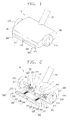
- a suction brush 10 according to an embodiment of the present disclosure includes a brush main body 100, first and second wheels 210 and 220, and first and second hair removing units 300.
- the brush main body 100 is provided with an upper housing 120 and a lower housing 110 (see FIG. 3 ).
- the lower housing 110 has a dust suction port 111, formed on a bottom surface thereof, for sucking in dust
- the upper housing 120 which is coupled to the lower housing 110, is connected to one end of an extension tube 20 the other end of which is connected to a cleaner main body (not illustrated) of a vacuum cleaner.
- the brush main body 100 has a suction flow path P, formed from the suction port 111 to the extension tube 20 in the brush main body 100, for passing therethrough sucked air, dust, and other dirt particles.
- the suction brush 10 which is connected to the cleaner main body through the extension tube 20, is applied to a canister type vacuum cleaner.
- the application of the suction brush 10 according to the present disclosure is not limited to a canister type vacuum cleaner, but is also compatible with an upright type vacuum cleaner.
- the first and second wheels 210 are rotatably coupled to both sides of the brush main body 100 through wheel shafts 211.
- the first and second hair removing units 300 are symmetrically arranged on the brush main body 100. Parts of the first and second removing units 300 are arranged adjacent to the wheel shafts 211 in the brush main body 100, and the remaining parts thereof are exposed to an outside of the brush main body 100. In this case, it is also possible to extend a front portion of the upper housing 120 of the brush main body 100 so that the extended front portion completely conceals the first and second hair removing units 300.
- the first hair removing unit 300 comprises a first cam member 310 and a first movable member 330.
- the first cam member 310 is rotatably arranged in the lower housing 110 (See FIG. 3 ) so that its rotation center coincides with a wheel shaft 211.
- the first cam member 310 has a projection portion 311 formed on one side of its outer periphery.
- the first cam member 310 receives a drive force generated when the first wheel 210 is rotated by a bevel gear unit 320.
- the bevel gear unit 320 comprises a first bevel gear 321 formed at one end of the wheel shaft 211, and a second bevel gear 322 arranged at a right angle to a shaft direction of the first bevel gear 321. Accordingly, the first cam member 310 receives a rotation drive force of the first wheel 210 that is rotated when the suction brush 10 moves forward and backward on the surface to be cleaned, and is rotated in one direction or in an opposite direction.
- the first movable member 330 comprises a cam contact unit 331, a connection unit 333, a return spring 335, a rib support unit 337, and a rib 339.
- the cam contact unit 331 is arranged adjacent to the first cam member 310 of the lower housing 110 so as to be in contact with the first cam member 310. As illustrated in FIG. 3 , the cam contact unit 331 is elastically moved in a forward or backward direction along the moving direction of the suction brush 10, by the return spring 335 installed in the connection unit 333, when the first cam member 310 is rotated.
- connection unit 333 connects the can contact unit 331 to the rib support unit 337, and transfers the driving force of the cam contact unit 331 to the rib support unit 337 arranged outside the brush main body 100.
- both ends of the connection unit 333 are connected to centers of the cam contact unit 331 and the rib support unit 337 so that the drive force of the can contact unit 331 is uniformly transferred to the rib support unit 337 through the connection unit 333.
- plural connection units 333 are provided to connect the cam contact unit 331 to the rib support unit 337.
- Upper housing 120 provides a hole 120a, through which connection unit 333 is passed.
- the return spring 335 In a state that the return spring 335 is coupled to the connection unit 333, an end of the return spring 335 is supported by a front side wall 121 of the upper housing 120, and another end of return spring 335 is supported by a stepped portion 333a of the connection unit 333. Accordingly, the return spring 335 elastically supports the cam contact unit 331 in a backward direction of the suction brush 10.
- the rib support unit 337 is formed with a specified length along the front portion of the brush main body 100, and at the lower end of the rib support unit 337 is coupled the rib 339 for raking up hair or pet fur that is stuck in a surface to be cleaned, for example, a carpet.
- the rib 339 is formed to extend to a position that is lower than the bottom surface of the brush main body 100, and as illustrated in FIG. 3 , the rib 339 is formed to be rounded toward the suction port 111 as it gets from its upper end (proximal to rib support unit 337) to its lower end (distal to rib support unit 337), so that the resistance between the rib 339 and the surface to be cleaned is minimized when the rib support unit 337 moves forward, while the hair or pet fur stuck in the carpet is effectively raked up toward the suction port 111 when the rib support unit 337 moves backward.
- the shape of the rib 339 is not limited thereto, and it is also possible that the rib is formed to be slanted in a straight line toward the suction port 111 as it gets from its upper end to its lower end.
- the rib 339 is made of a soft material so that it does not damage the carpet.
- the first and second hair removing units 300 are provided as a pair of hair removing units, but are not limited thereto. It is also possible that a single hair removing unit is provided to be driven by the rotation drive force from either of the first and second wheels 210. In the case where a single hair removing unit is provided, it is preferable that the rib support unit 337 be formed to have a length corresponding to the whole front portion of the brush main body 100, and the cam contact unit 331 having a length corresponding to the length of the rib support unit 337 is connected to the rib support unit 337.
- the suction brush 10 When a user cleans a surface to be cleaned, for example, a carpet (not illustrated), he/she moves the suction brush 10 forward and backward on the carpet. In this case, as illustrated in FIG. 1 , the first and second wheels 210 are rotated in one direction or in an opposite direction, by the movement of the suction brush 10, and transfer their respective drive forces to the first and second cam members 310 of the first and second hair removing unit 300.
- first and second cam members 310 drive the first and second movable members 330 as they rotate in one direction and in an opposite direction.
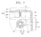
- first and second hair removing units perform the same operation, only the operation of the first hair removing unit 300 will be described with reference to FIGS. 4 to 7 .
- the cam contact unit 331 of the first hair removing unit 300 is rotated clockwise as shown in FIG. 5 in a state that the cam contact unit 331 is in contact with a portion that is not the projection portion 311 as shown in FIG. 4 , the projection portion 311 of the first cam member 310 pushes the can contact unit 331 of the first movable member 330, and the rib support unit 337 of the first movable member 330 moves in a forward moving direction of the suction brush 10 to make the rib 339 move forward.
- the rib 339 which moves backward (i.e. toward suction port 111), rakes up the hair or pet fur that is deeply stuck in the carpet toward the suction port 111.
- the suction brush 10 sucks in the hair or pet fur raked up toward the suction port 111 by the rib 339 with a high suction force, and thus the cleaning efficiency can be maximized.
- first and second cam members 310 make the first and second movable members 330 move forward and backward as they rotate clockwise and counterclockwise as described above, the hair or pet fur stuck in the carpet can be effectively removed through the ribs 339 and 439.
- the hair removing units are driven by the driving forces of the wheels without an obstacle such as a conventional turbine in the suction flow path, the hair existing on the surface to be cleaned can be effectively removed with the deterioration of the suction force in the suction brush prevented, and thus the cleaning efficiency can be increased.
Landscapes
- Engineering & Computer Science (AREA)
- Mechanical Engineering (AREA)
- Nozzles For Electric Vacuum Cleaners (AREA)
Applications Claiming Priority (1)
| Application Number | Priority Date | Filing Date | Title |
|---|---|---|---|
| KR1020070072678A KR101401512B1 (ko) | 2007-07-20 | 2007-07-20 | 진공청소기용 흡입브러시 |
Publications (3)
| Publication Number | Publication Date |
|---|---|
| EP2016882A2 true EP2016882A2 (de) | 2009-01-21 |
| EP2016882A3 EP2016882A3 (de) | 2009-09-02 |
| EP2016882B1 EP2016882B1 (de) | 2014-10-29 |
Family
ID=39901125
Family Applications (1)
| Application Number | Title | Priority Date | Filing Date |
|---|---|---|---|
| EP08103951.3A Ceased EP2016882B1 (de) | 2007-07-20 | 2008-05-14 | Saugbürste für einen Staubsauger |
Country Status (3)
| Country | Link |
|---|---|
| US (1) | US8032985B2 (de) |
| EP (1) | EP2016882B1 (de) |
| KR (1) | KR101401512B1 (de) |
Cited By (9)
| Publication number | Priority date | Publication date | Assignee | Title |
|---|---|---|---|---|
| CN109431371A (zh) * | 2018-12-17 | 2019-03-08 | 小狗电器互联网科技(北京)股份有限公司 | 一种双滚地刷及吸尘器 |
| CN111305121A (zh) * | 2020-02-17 | 2020-06-19 | 中国人民解放军空军勤务学院 | 机场路面清扫车清扫毯收纳装置 |
| US11058278B2 (en) | 2018-04-30 | 2021-07-13 | Lg Electronics Inc. | Nozzle for cleaner |
| TWI736882B (zh) * | 2018-04-30 | 2021-08-21 | 南韓商Lg電子股份有限公司 | 用於清掃機的吸嘴 |
| US11096536B2 (en) | 2018-04-30 | 2021-08-24 | Lg Electronics Inc. | Nozzle for cleaner |
| US11154172B2 (en) | 2018-04-30 | 2021-10-26 | Lg Electronics Inc. | Nozzle for cleaner |
| US11191415B2 (en) | 2018-04-30 | 2021-12-07 | Lg Electronics Inc. | Nozzle for cleaner |
| US11426041B2 (en) | 2018-07-30 | 2022-08-30 | Lg Electronics Inc. | Nozzle for cleaner |
| US12616345B2 (en) | 2018-04-30 | 2026-05-05 | Lg Electronics Inc. | Nozzle for cleaner |
Families Citing this family (11)
| Publication number | Priority date | Publication date | Assignee | Title |
|---|---|---|---|---|
| US11992172B2 (en) | 2018-10-19 | 2024-05-28 | Sharkninja Operating Llc | Agitator for a surface treatment apparatus and a surface treatment apparatus having the same |
| TWI582322B (zh) * | 2016-01-26 | 2017-05-11 | 日本電產股份有限公司 | 車輪驅動裝置及使用該裝置的掃除機器人 |
| US10925447B2 (en) | 2017-03-10 | 2021-02-23 | Sharkninja Operating Llc | Agitator with debrider and hair removal |
| US11202542B2 (en) | 2017-05-25 | 2021-12-21 | Sharkninja Operating Llc | Robotic cleaner with dual cleaning rollers |
| WO2019035050A1 (en) | 2017-08-16 | 2019-02-21 | Sharkninja Operating, Llc | ROBOT VACUUM |
| KR20250002800A (ko) | 2018-10-19 | 2025-01-07 | 샤크닌자 오퍼레이팅 엘엘씨 | 표면 처리 장치용 교란기 및 이를 갖는 표면 장치 |
| KR102171885B1 (ko) * | 2019-10-29 | 2020-10-30 | 이지산 | 쓰레받기 |
| CN111956129B (zh) * | 2020-08-25 | 2021-07-27 | 陈志君 | 一种工业除尘装置 |
| KR20220120133A (ko) * | 2021-02-23 | 2022-08-30 | 엘지전자 주식회사 | 로봇 청소기 |
| KR20220121498A (ko) * | 2021-02-25 | 2022-09-01 | 엘지전자 주식회사 | 청소기 및 청소기의 흡입 모듈 |
| CN113749573A (zh) * | 2021-09-30 | 2021-12-07 | 深圳市杉川机器人有限公司 | 一种洗地机 |
Citations (2)
| Publication number | Priority date | Publication date | Assignee | Title |
|---|---|---|---|---|
| DE2428400A1 (de) | 1974-06-12 | 1976-01-02 | Bosch Siemens Hausgeraete | Staubsaugerduese |
| GB2386055A (en) | 2002-03-04 | 2003-09-10 | Samsung Kwangju Electronics Co | A nozzle assembly for a vacuum cleaner |
Family Cites Families (10)
| Publication number | Priority date | Publication date | Assignee | Title |
|---|---|---|---|---|
| US1336760A (en) | 1919-03-13 | 1920-04-13 | Claude W Stewart | Vacuum-cleaner |
| SE387836B (sv) | 1974-12-19 | 1976-09-20 | Electrolux Ab | Dammsugarmunstycke |
| KR900006624B1 (ko) | 1987-08-06 | 1990-09-15 | 마쯔시다덴기산교 가부시기가이샤 | 전기소제기의 침구용 흡입기구 |
| CA2192882C (en) * | 1996-01-23 | 2002-04-16 | Shigenori Hato | Suction tool for an electric vacuum cleaner |
| KR0165065B1 (ko) | 1996-02-07 | 1999-01-15 | 구자홍 | 진공청소기의 흡입구 |
| KR0170848B1 (ko) | 1996-07-12 | 1999-01-15 | 구자홍 | 진공청소기의 상용흡입구 |
| KR200317705Y1 (ko) | 2003-01-27 | 2003-06-25 | 박동원 | 방바닥을 닦는 모터 청소기 |
| KR20060055987A (ko) * | 2004-11-19 | 2006-05-24 | 주식회사 대우일렉트로닉스 | 진공청소기의 브러쉬 회전장치 |
| US8117714B2 (en) | 2005-03-09 | 2012-02-21 | Bissell Homecare, Inc. | Vacuum cleaner with hair collection element |
| JP4621544B2 (ja) | 2005-06-08 | 2011-01-26 | 株式会社東芝 | 吸込口体及びこれを備える電気掃除機 |
-
2007
- 2007-07-20 KR KR1020070072678A patent/KR101401512B1/ko not_active Expired - Fee Related
-
2008
- 2008-01-10 US US12/008,295 patent/US8032985B2/en active Active
- 2008-05-14 EP EP08103951.3A patent/EP2016882B1/de not_active Ceased
Patent Citations (2)
| Publication number | Priority date | Publication date | Assignee | Title |
|---|---|---|---|---|
| DE2428400A1 (de) | 1974-06-12 | 1976-01-02 | Bosch Siemens Hausgeraete | Staubsaugerduese |
| GB2386055A (en) | 2002-03-04 | 2003-09-10 | Samsung Kwangju Electronics Co | A nozzle assembly for a vacuum cleaner |
Cited By (31)
| Publication number | Priority date | Publication date | Assignee | Title |
|---|---|---|---|---|
| US11896188B2 (en) | 2018-04-30 | 2024-02-13 | Lg Electronics Inc. | Nozzle for cleaner |
| US11659973B2 (en) | 2018-04-30 | 2023-05-30 | Lg Electronics Inc. | Nozzle for cleaner |
| US11058278B2 (en) | 2018-04-30 | 2021-07-13 | Lg Electronics Inc. | Nozzle for cleaner |
| TWI736882B (zh) * | 2018-04-30 | 2021-08-21 | 南韓商Lg電子股份有限公司 | 用於清掃機的吸嘴 |
| US11096536B2 (en) | 2018-04-30 | 2021-08-24 | Lg Electronics Inc. | Nozzle for cleaner |
| US11154172B2 (en) | 2018-04-30 | 2021-10-26 | Lg Electronics Inc. | Nozzle for cleaner |
| US11191415B2 (en) | 2018-04-30 | 2021-12-07 | Lg Electronics Inc. | Nozzle for cleaner |
| TWI769891B (zh) * | 2018-04-30 | 2022-07-01 | 南韓商Lg電子股份有限公司 | 清掃機 |
| US12616345B2 (en) | 2018-04-30 | 2026-05-05 | Lg Electronics Inc. | Nozzle for cleaner |
| US11517174B2 (en) | 2018-04-30 | 2022-12-06 | Lg Electronics Inc. | Nozzle for cleaner |
| US11517173B2 (en) | 2018-04-30 | 2022-12-06 | Lg Electronics Inc. | Nozzle for cleaner |
| US12082756B2 (en) | 2018-04-30 | 2024-09-10 | Lg Electronics Inc. | Nozzle for cleaner |
| US12551074B2 (en) | 2018-04-30 | 2026-02-17 | Lg Electronics Inc. | Nozzle for cleaner |
| US11786093B2 (en) | 2018-04-30 | 2023-10-17 | Lg Electronics Inc. | Nozzle for cleaner |
| US12551069B2 (en) | 2018-04-30 | 2026-02-17 | Lg Electronics Inc. | Nozzle for cleaner |
| US12446751B2 (en) | 2018-04-30 | 2025-10-21 | Lg Electronics Inc. | Nozzle for cleaner |
| US11944249B2 (en) | 2018-04-30 | 2024-04-02 | Lg Electronics Inc. | Nozzle for cleaner |
| US12251062B2 (en) | 2018-04-30 | 2025-03-18 | Lg Electronics Inc. | Nozzle for cleaner |
| US11937752B2 (en) | 2018-04-30 | 2024-03-26 | Lg Electronics Inc. | Nozzle for cleaner |
| US11957296B2 (en) | 2018-04-30 | 2024-04-16 | Lg Electronics Inc. | Nozzle for cleaner |
| US12029361B2 (en) | 2018-04-30 | 2024-07-09 | Lg Electronics Inc. | Nozzle for cleaner |
| US12029364B2 (en) | 2018-04-30 | 2024-07-09 | Lg Electronics Inc. | Nozzle for cleaner |
| US12035862B2 (en) | 2018-04-30 | 2024-07-16 | Lg Electronics Inc. | Nozzle for cleaner |
| US12042116B2 (en) | 2018-04-30 | 2024-07-23 | Lg Electronics Inc. | Nozzle for cleaner |
| US11426041B2 (en) | 2018-07-30 | 2022-08-30 | Lg Electronics Inc. | Nozzle for cleaner |
| US12185898B2 (en) | 2018-07-30 | 2025-01-07 | Lg Electronics Inc. | Nozzle for cleaner |
| US11944257B2 (en) | 2018-07-30 | 2024-04-02 | Lg Electronics Inc. | Nozzle for cleaner |
| CN109431371B (zh) * | 2018-12-17 | 2024-04-02 | 小狗电器互联网科技(北京)股份有限公司 | 一种双滚地刷及吸尘器 |
| CN109431371A (zh) * | 2018-12-17 | 2019-03-08 | 小狗电器互联网科技(北京)股份有限公司 | 一种双滚地刷及吸尘器 |
| CN111305121A (zh) * | 2020-02-17 | 2020-06-19 | 中国人民解放军空军勤务学院 | 机场路面清扫车清扫毯收纳装置 |
| CN111305121B (zh) * | 2020-02-17 | 2023-06-27 | 中国人民解放军空军勤务学院 | 机场路面清扫车清扫毯收纳装置 |
Also Published As
| Publication number | Publication date |
|---|---|
| US8032985B2 (en) | 2011-10-11 |
| KR20090009425A (ko) | 2009-01-23 |
| KR101401512B1 (ko) | 2014-06-03 |
| EP2016882B1 (de) | 2014-10-29 |
| EP2016882A3 (de) | 2009-09-02 |
| US20090019661A1 (en) | 2009-01-22 |
Similar Documents
| Publication | Publication Date | Title |
|---|---|---|
| US8032985B2 (en) | Suction brush for vacuum cleaner | |
| US20100205768A1 (en) | Brush assembly of vacuum cleaner | |
| JP5227451B2 (ja) | 掃除機ヘッド | |
| CN111031872B (zh) | 真空清洁器 | |
| JP5394471B2 (ja) | 掃除機ヘッド | |
| CN106691315B (zh) | 用于吸尘器的滚筒以及具有该滚筒的吸尘器 | |
| CN101589933B (zh) | 吸入口体及电动吸尘器 | |
| CN101152066B (zh) | 吸尘器吸尘头及使用这种吸尘头的电动吸尘器 | |
| JP5227452B2 (ja) | 掃除機ヘッド | |
| JP2639155B2 (ja) | 電気掃除機 | |
| CN114745996A (zh) | 真空吸尘器 | |
| JP2009017902A (ja) | 電気掃除機の吸口体及びこれを用いた電気掃除機 | |
| EP4223196B1 (de) | Staubsauger und reinigungszubehör für einen staubsauger | |
| JP2002143049A (ja) | 吸込み口体及び電気掃除機 | |
| EP4223197B1 (de) | Staubsauger und reinigungszubehör für einen staubsauger | |
| JP2009153876A (ja) | 吸込口体および電気掃除機 | |
| US20230355050A1 (en) | Handheld vacuum device | |
| CN119233780A (zh) | 用于真空吸尘器的吸尘器头 | |
| JP5622830B2 (ja) | 電気掃除機の吸口体 | |
| JP3128046B2 (ja) | 電気掃除機の吸込口体 | |
| JP5038880B2 (ja) | 吸込口体および電気掃除機 | |
| EP4223195B1 (de) | Staubsauger und reinigungszubehör für einen staubsauger | |
| JP7809378B2 (ja) | 吸込具及び電気掃除機 | |
| KR100767061B1 (ko) | 청소기 | |
| EP4223198B1 (de) | Staubsauger und reinigungszubehör für einen staubsauger |
Legal Events
| Date | Code | Title | Description |
|---|---|---|---|
| PUAI | Public reference made under article 153(3) epc to a published international application that has entered the european phase |
Free format text: ORIGINAL CODE: 0009012 |
|
| AK | Designated contracting states |
Kind code of ref document: A2 Designated state(s): AT BE BG CH CY CZ DE DK EE ES FI FR GB GR HR HU IE IS IT LI LT LU LV MC MT NL NO PL PT RO SE SI SK TR |
|
| AX | Request for extension of the european patent |
Extension state: AL BA MK RS |
|
| PUAL | Search report despatched |
Free format text: ORIGINAL CODE: 0009013 |
|
| AK | Designated contracting states |
Kind code of ref document: A3 Designated state(s): AT BE BG CH CY CZ DE DK EE ES FI FR GB GR HR HU IE IS IT LI LT LU LV MC MT NL NO PL PT RO SE SI SK TR |
|
| AX | Request for extension of the european patent |
Extension state: AL BA MK RS |
|
| 17P | Request for examination filed |
Effective date: 20091126 |
|
| AKX | Designation fees paid |
Designated state(s): DE FR GB IT |
|
| RAP1 | Party data changed (applicant data changed or rights of an application transferred) |
Owner name: SAMSUNG ELECTRONICS CO., LTD. |
|
| RAP1 | Party data changed (applicant data changed or rights of an application transferred) |
Owner name: SAMSUNG ELECTRONICS CO., LTD. |
|
| 17Q | First examination report despatched |
Effective date: 20130619 |
|
| GRAP | Despatch of communication of intention to grant a patent |
Free format text: ORIGINAL CODE: EPIDOSNIGR1 |
|
| INTG | Intention to grant announced |
Effective date: 20140522 |
|
| GRAS | Grant fee paid |
Free format text: ORIGINAL CODE: EPIDOSNIGR3 |
|
| GRAA | (expected) grant |
Free format text: ORIGINAL CODE: 0009210 |
|
| AK | Designated contracting states |
Kind code of ref document: B1 Designated state(s): DE FR GB IT |
|
| REG | Reference to a national code |
Ref country code: GB Ref legal event code: FG4D |
|
| REG | Reference to a national code |
Ref country code: DE Ref legal event code: R096 Ref document number: 602008035071 Country of ref document: DE Effective date: 20141211 |
|
| REG | Reference to a national code |
Ref country code: DE Ref legal event code: R097 Ref document number: 602008035071 Country of ref document: DE |
|
| PG25 | Lapsed in a contracting state [announced via postgrant information from national office to epo] |
Ref country code: IT Free format text: LAPSE BECAUSE OF FAILURE TO SUBMIT A TRANSLATION OF THE DESCRIPTION OR TO PAY THE FEE WITHIN THE PRESCRIBED TIME-LIMIT Effective date: 20141029 |
|
| PLBE | No opposition filed within time limit |
Free format text: ORIGINAL CODE: 0009261 |
|
| STAA | Information on the status of an ep patent application or granted ep patent |
Free format text: STATUS: NO OPPOSITION FILED WITHIN TIME LIMIT |
|
| 26N | No opposition filed |
Effective date: 20150730 |
|
| REG | Reference to a national code |
Ref country code: FR Ref legal event code: PLFP Year of fee payment: 9 |
|
| REG | Reference to a national code |
Ref country code: FR Ref legal event code: PLFP Year of fee payment: 10 |
|
| REG | Reference to a national code |
Ref country code: FR Ref legal event code: PLFP Year of fee payment: 11 |
|
| PGFP | Annual fee paid to national office [announced via postgrant information from national office to epo] |
Ref country code: DE Payment date: 20200421 Year of fee payment: 13 Ref country code: FR Payment date: 20200423 Year of fee payment: 13 |
|
| PGFP | Annual fee paid to national office [announced via postgrant information from national office to epo] |
Ref country code: GB Payment date: 20200423 Year of fee payment: 13 |
|
| REG | Reference to a national code |
Ref country code: DE Ref legal event code: R119 Ref document number: 602008035071 Country of ref document: DE |
|
| GBPC | Gb: european patent ceased through non-payment of renewal fee |
Effective date: 20210514 |
|
| PG25 | Lapsed in a contracting state [announced via postgrant information from national office to epo] |
Ref country code: GB Free format text: LAPSE BECAUSE OF NON-PAYMENT OF DUE FEES Effective date: 20210514 Ref country code: DE Free format text: LAPSE BECAUSE OF NON-PAYMENT OF DUE FEES Effective date: 20211201 |
|
| PG25 | Lapsed in a contracting state [announced via postgrant information from national office to epo] |
Ref country code: FR Free format text: LAPSE BECAUSE OF NON-PAYMENT OF DUE FEES Effective date: 20210531 |