EP2016925B1 - Rollstuhlrückhaltungen - Google Patents
Rollstuhlrückhaltungen Download PDFInfo
- Publication number
- EP2016925B1 EP2016925B1 EP20080252462 EP08252462A EP2016925B1 EP 2016925 B1 EP2016925 B1 EP 2016925B1 EP 20080252462 EP20080252462 EP 20080252462 EP 08252462 A EP08252462 A EP 08252462A EP 2016925 B1 EP2016925 B1 EP 2016925B1
- Authority
- EP
- European Patent Office
- Prior art keywords
- wheelchair
- spools
- restraint
- members
- vehicle
- Prior art date
- Legal status (The legal status is an assumption and is not a legal conclusion. Google has not performed a legal analysis and makes no representation as to the accuracy of the status listed.)
- Active
Links
Images


Classifications
-
- A—HUMAN NECESSITIES
- A61—MEDICAL OR VETERINARY SCIENCE; HYGIENE
- A61G—TRANSPORT, PERSONAL CONVEYANCES, OR ACCOMMODATION SPECIALLY ADAPTED FOR PATIENTS OR DISABLED PERSONS; OPERATING TABLES OR CHAIRS; CHAIRS FOR DENTISTRY; FUNERAL DEVICES
- A61G3/00—Ambulance aspects of vehicles; Vehicles with special provisions for transporting patients or disabled persons, or their personal conveyances, e.g. for facilitating access of, or for loading, wheelchairs
- A61G3/02—Loading or unloading personal conveyances; Facilitating access of patients or disabled persons to, or exit from, vehicles
-
- A—HUMAN NECESSITIES
- A61—MEDICAL OR VETERINARY SCIENCE; HYGIENE
- A61G—TRANSPORT, PERSONAL CONVEYANCES, OR ACCOMMODATION SPECIALLY ADAPTED FOR PATIENTS OR DISABLED PERSONS; OPERATING TABLES OR CHAIRS; CHAIRS FOR DENTISTRY; FUNERAL DEVICES
- A61G3/00—Ambulance aspects of vehicles; Vehicles with special provisions for transporting patients or disabled persons, or their personal conveyances, e.g. for facilitating access of, or for loading, wheelchairs
- A61G3/08—Accommodating or securing wheelchairs or stretchers
- A61G3/0808—Accommodating or securing wheelchairs
Definitions
- This invention relates to wheelchair restraints.
- two belts are secured to the front of the wheelchair and two to the rear. Belt lengths are adjusted to suit the wheelchair and the front belts are locked.
- the rear belts are normally fitted with a tensioning device, which prevents the wheelchair from moving around in transit.
- the front restraints comprise a pair of spools containing seat belt webbing which have a hook or karabiner or buckle and tongue arrangement fitted to one end for attachment to the wheelchair.
- the spools are fitted into frames and are spring loaded, causing webbing to be wound onto the spool.
- a ratchet mechanism prevents the webbing from being unwound until a solenoid valve is operated which disengages the ratchet and allows the belts to be extended and fitted to the wheelchair outside the vehicle. Once the solenoid is de-energised, the ratchet is re-engaged and the wheelchair can be loaded into the vehicle. Springs wind the belts back onto the spools as this happens. The ratchet mechanism now prevents the belts from being unwound from the spools, preventing the wheelchair from rolling backwards.
- Such spring-loaded, ratchet driven spools are known from the seatbelt systems of cabs of heavy goods vehicles, where the solenoid-controlled ratchet is used to prevent unwinding of the driver's seatbelt and hence restrain the driver in the event of a crash, based upon the output of a deceleration sensor fitted to the vehicle cab.
- spools are generally used in prior-art wheelchair restraint systems, they are made in large volumes for the heavy goods vehicle market and are available relatively cheaply.
- a problem with this type of restraint is that the webbing capacity is too little to allow fitting to the wheelchair outside a large vehicle. It is not considered practical simply to provide higher capacity spools, as it is not considered economic in the niche market relating to wheelchair restraints to set up the tooling etc required to make the spool and retraction mechanism combined. Another problem is that there is no manual override to the solenoid valve, failure of which renders the belts unusable.
- a wheelchair restraint for use in a vehicle comprising:
- This invention therefore removes the need for a complicated spring-return mechanism within each spool; the spools can be driven relatively simply by the common drive means.
- the spools can be of any desired size, as manufacture of the spools of differing sizes without the need to generate correspondingly different size return mechanisms within the spool would be easier than the prior art manufacturing situation described above.
- the spools may be linked together by a shaft.
- the spools may be linked by the shaft such that they rotate together.
- the use of such a shaft is convenient, as it means that the spools will rotate at the same speed, therefore drawing in their respective members at the same rate. This is likely to prevent the two members retracting at different speeds to one another, which could lead to the wheelchair being unevenly restrained.
- the common drive means may be operatively coupled to, and may be situated on, the shaft.
- the common drive means may be arranged such that, in use, the force applied by the members on the wheelchair is sufficient to coil the members on the spools as the wheelchair is moved into the vehicle but is not sufficient to pull the wheelchair into the vehicle.
- the maximum force applied on each of the members by the action of the common drive means in use is less than 50N, and is preferably less than 30N.
- the torque applied by the common drive means on the spools may be substantially constant as the members are coiled on the spools, and may generate a force of 25N on each of the members when the members are fully coiled.
- the common drive means may comprise a spring motor, typically a constant force spring motor.
- the common drive means may comprise an electric or hydraulic motor; in such a case the electric or hydraulic motor may be provided with a clutch that can selectively disengage the motor from the spools. This can be advantageous, as it means that the motor does not necessarily have to be back-wound when releasing the windable members from the spools.
- the restraint may also be provided with a common ratchet having two states; a first state in which it acts to prevent the members being uncoiled from the spools by preventing rotation of the spools in a first sense, but allows rotation of the spools in a second, opposite sense, and a second state where it allows rotation of the spools in either sense. Accordingly, a ratchet does not have to be provided in each spool.
- the ratchet may be provided in the same housing as the common drive means.
- the ratchet may comprise a solenoid, which is arranged to switch the ratchet between the first and second states. Additionally or alternatively, the ratchet may be provided with a release handle, arranged to switch the ratchet between the first and second states.
- the ratchet may comprise a toothed wheel mounted on the shaft and at least one pawl biased into contact with the toothed wheel in the first state; as is common with ratchet mechanisms, the shape of the toothed wheel may be such that in the first state the pawl rises over the teeth of the toothed wheel as the shaft rotates in the first sense but locks against the teeth as the shaft rotates in the second sense.
- At least one of any solenoid and any release handle may be operatively coupled to the pawl so as to force the pawl out of engagement with the toothed wheel in the second state. Having both a solenoid and manual handle operation is convenient, as the manual handle provides a backup should the solenoid fail.
- Each of the members may comprise a band of webbing, typically of the kind commonly employed in vehicular seat belts.
- the attachment means may comprise a hook, buckle or karabiner or other such attachment hardware.
- the restraint may further comprise a further motor arranged so as to be able to retract the windable members, the further motor being capable of exerting sufficient force on the members so as to be able to load a wheelchair carrying a person into the vehicle.
- the motor may be arranged so as to be able to exert a force of at least 2500 N on the members.
- the motor would be arranged to drive the shaft.
- the further motor may be provided with a clutch, so as to enable to motor to be selectively engaged to drive the spools. This may enable the motor to be disengaged from the spools when the members are being unwound from the spools, hence avoiding back-winding the motor.
- the spring motor (and, if provided, the common ratchet) will still function to provide a restraint against movement of the wheelchair.
- a vehicle fitted with the wheelchair restraint of the first aspect of the invention.
- the members may be of sufficient length to reach a wheelchair outside the vehicle when they are fully uncoiled from the spools.
- a third aspect of the invention there is provided a combination of the vehicle of the second aspect of the invention and a wheelchair, the attachment means of the wheelchair restraint being attached to the wheelchair.
- a method of loading a wheelchair into a vehicle comprising attaching the attachment means to the wheelchair and moving the wheelchair into a desired position, allowing the common drive means to rotate the spools so as to coil the members on the spools. Accordingly, the wheelchair can be located correctly in the vehicle and then the slack in the members taken up.
- the method may comprise the step of extending the members to reach the wheelchair in the second position of the ratchet, typically by uncoiling them from the spools. Once the members are attached to the wheelchair, the method may comprise placing the ratchet in the first position whilst the wheelchair is moved into the desired position. This means that the wheelchair will be prevented in moving in the direction away from the spools - typically backwards - whilst it is being moved into the desired position.
- the wheelchair may be positioned outside the vehicle when the members are attached; the desired position may be inside the vehicle, typically a driving position in front of the controls of the vehicle.
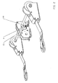
- a wheelchair restraint according to a first embodiment of the present invention is shown in Figures 1 to 5 of the accompanying Figures.
- This restraint comprises two spools 15 with webbing 1 of the kind commonly used for vehicle seat belts coiled around them.
- a captive end (not shown) of each length of webbing 1 is held in the respective spool 15.
- the other, free end of each length of webbing is fitted with a "karabiner" 16; that is a hook having a spring-loaded gate.
- This can be used to attach the free end of each length of webbing 1 to a suitable point on a wheelchair; the hook is passed over a strut or similar part of the wheelchair, and the spring-loaded gate 17 prevents the strut inadvertently escaping the hook.
- the two spools 15 are linked by a shaft 8 which rotates in a housing 18 bolted to the vehicle floor in front of the desired wheelchair position.
- This shaft 8 is powered by a constant force spring motor 2.
- the shaft acts to rotate the spools 15 in a first sense shown by arrow 20 to cause the webbing 1 to be wound onto the spools 15.
- the motor 2 exerts a pull equivalent to the weight of a mass of approximately 2.5 kg (that is, about 25N) on each of the lengths of webbing 1.
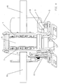
- a ratchet 6 prevents rotation of the shaft and hence the spools in the sense opposite to that of arrow 20; hence the webbing is prevented from unwinding.
- ratchet pawls 5 ( Figure 4 ) are mounted on a shaft 21 in housing 18.
- a pair of toothed wheels 7 is fixed to shaft 8 and so rotate with it.
- the ratchet pawl shaft 21 has a lever at each end; a first one of these 9 is attached via a pin to a solenoid 3.
- the other lever 10 is fitted to a tension spring 11, which keeps the ratchet pawls 5 engaged with the toothed wheels 7.
- manual lever 4 can be used to disengage the ratchet pawls.
- the lever 4 swivels about the ratchet pawl shaft 21 and is mounted between two cylindrical rubber spacers 12, which hold the lever against a face cam 13. Rotating the lever causes the ratchet pawls to be disengaged.
- the lever 4 is held off by a notch 23 in the face cam 13.
- FIG. 5 of the accompanying drawings This depicts schematically a car 30 fitted with the wheelchair restraint 31 of Figures 1 to 4 .
- the ratchet 6 has been released by means of the solenoid 3 or manual release lever 4.
- the webbing 1 is substantially unwound from the spools 15 so that it reaches the wheelchair 33 to be loaded onto the vehicle 30.
- the karabiners 16 are used to fix the webbing 1 to the wheelchair 33.
- the ratchet is then reengaged by allowing pawls 5 to come back into contact with toothed wheels 7.
- the webbing can therefore no longer be extended, and the constant force spring motor 2 will apply its force to tend to retract the webbing 1 onto the spools 15.
- the wheelchair 33 in then loaded into the vehicle 30 via ramp 34 towards desired location 32. As it is so loaded, the webbing retracts onto the spools by action of the motor 2; the ratchet prevents the wheelchair rolling backwards. Once the wheelchair is in the desired position, it is prevented from any backwards movement by the ratchet. Forwards movement can be restrained by using with any available rear tie-down and tensioning device.
- FIG. 6 A second embodiment of the invention is shown in Figures 6 and 7 of the accompanying drawings.
- two spools containing seat belt webbing terminated at a free end with a "karabiner" 51 are linked by a shaft 58 which rotates in a framework bolted to the vehicle floor in front of the wheelchair.
- This shaft 58 is powered by a constant force spring motor 52 which, when engaged and as with the first embodiment, causes the belts to be fully wound onto the spools.
- the motor has been relocated with respect to the first embodiment of the invention, and is now located at an end of the shaft 58 adjacent to one of the spools.
- the spring motor 52 is designed to exert a pull of about 25N (equivalent to 2.5 kg) on the belts; a ratchet prevents the belts from unwinding until disengaged by a solenoid valve 53 or manual override lever 54. These release mechanisms allow the belts to be fully unwound from their spools and attached to a wheelchair outside the vehicle.
- the ratchet mechanism is shown in more detail in Figure 7 of the accompanying drawings.
- the ratchet pawls 59 are mounted on a shaft running through the spool housing 60.
- the spool is attached to a pair of toothed wheels 61.
- the ratchet pawl shaft 59 has a lever 54 at one end, which is attached via a pin to the solenoid 53.
- This lever 54 carries an extension, which acts as a manual override should the solenoid fail and is fitted to a tension spring 62 which keeps the ratchet pawls engaged with the toothed wheels.
- the solenoid is energised, the spring force is overcome and the ratchet pawls are disengaged from the toothed wheel, allowing the safety belts 51 to be unwound.
- the extension to the lever 54 can be used to disengage the ratchet pawls.
- the belts can be tensioned using an electric motor 55, fitted with a reduction gearbox 56 and a magnetic clutch 57.
- This electric motor 55 revolves the shaft 58 linking the webbing spools, tensioning the belts and preventing unwanted wheelchair movement. Clutch slippage prevents over tensioning of the belts and damage to the wheelchair. Once switched off, the motor is disengaged and the restraint works as described previously.
- this motor 55 and clutch 57 assembly can be utilised as a device for winching non-motorised wheelchairs into the vehicle.
- This system has several advantages over conventional winch and restraint systems. With the clutch 57 disengaged, the belts can be withdrawn from the vehicle without having to back-wind the motor, and separate restraint belts do not have to be fitted.
Landscapes
- Health & Medical Sciences (AREA)
- Public Health (AREA)
- Life Sciences & Earth Sciences (AREA)
- Animal Behavior & Ethology (AREA)
- General Health & Medical Sciences (AREA)
- Veterinary Medicine (AREA)
- Automotive Seat Belt Assembly (AREA)
Claims (16)
- Rollstuhlrückhalter zur Verwendung in einem Fahrzeug, umfassend:erste und zweite Rollen (15), die dazu ausgestaltet sind, drehbeweglich an dem Fahrzeug angebracht zu sein,für jede Rolle ein Element (1), das in der Lage ist, auf die Rolle gewickelt zu sein, an einem festgehaltenen Ende mit der Rolle verbunden ist und an dem anderen,freien Ende mit Befestigungsmitteln (16) zum Befestigen des wickelbaren Elementes an einem Rollstuhl versehen ist,wobei ein gemeinsames Antriebsmittel (2) vorgesehen ist, das von jeder Rolle beabstandet ist und dazu ausgestaltet ist, in Verwendung eine Kraft auf die Rollen (15) anzuwenden, um die Wirkung auszuüben, die wickelbaren Elemente (1) auf die Rollen (15) zu wickeln,dadurch gekennzeichnet, dass er einen weiteren Motor (55) umfasst, der dazu ausgestaltet ist, zum Einziehen der wickelbaren Elemente (1) in der Lage zu sein, wobei der weitere Motor (55) in der Lage ist, ausreichende Kraft auf die Elemente (1) auszuüben, um in der Lage zu sein, einen Rollstuhl, der eine Person trägt, in das Fahrzeug zu laden.
- Rollstuhlrückhalter zur Verwendung in einem Fahrzeug, umfassend;
erste und zweite Rollen (15), die dazu ausgestaltet sind, drehbeweglich an dem Fahrzeug angebracht zu sein, für jede Rolle ein Element (1), das in der Lage ist, auf die Rolle (15) gewickelt zu sein, an einem festgehaltenen Ende mit der Rolle verbunden ist und an dem anderen, freien Ende mit Befestigungsmitteln (16) zum Befestigen des wickelbaren Elementes (1) an einem Rollstuhl versehen ist,
wobei ein gemeinsames Antriebsmittel (2) vorgesehen ist, das von jeder Rolle (15) beabstandet ist und dazu ausgestaltet ist, in Verwendung eine Kraft auf die Rollen (15) anzuwenden, um die Wirkung auszuüben, die Elemente (1) auf die Rollen (15) zu wickeln,
dadurch gekennzeichnet, dass das gemeinsame Antriebsmittel (2) so ausgestaltet ist, dass in Verwendung die von den Elementen (1) auf den Rollstuhl angewandte Kraft ausreichend ist, um die Elemente (1) auf die Rollen (15) aufzurollen, während der Rollstuhl in das Fahrzeug bewegt wird, aber nicht ausreichend ist, um den Rollstuhl in das Fahrzeug zu ziehen; und wobei die maximale Kraft, die durch die Wirkung des gemeinsamen Antriebsmittels (2) in Verwendung auf jedes der Elemente (1) angewandt wird, weniger als 50 N beträgt. - Rückhalter gemäß Anspruch 1 oder 2, wobei die Rollen (15) durch eine Welle (8) miteinander verbunden sind, so dass sie zusammen rotieren.
- Rückhalter gemäß Anspruch 3, wobei das gemeinsame Antriebsmittel (2) mit der Welle (8) wirkverbunden ist.
- Rückhalter gemäß Anspruch 1, wobei das gemeinsame Antriebsmittel (2) so ausgestaltet ist, dass in Verwendung die von den Elementen (1) auf den Rollstuhl angewandte Kraft ausreichend ist, um die Elemente (1) auf die Rollen (15) aufzurollen, während der Rollstuhl in das Fahrzeug bewegt wird, aber nicht ausreichend ist, um den Rollstuhl in das Fahrzeug zu ziehen.
- Rückhalter gemäß Anspruch 2 oder Anspruch 5, wobei die maximale durch die Wirkung des gemeinsamen Antriebsmittels (2) in Verwendung auf jedes der Elemente (1) angewandte Kraft weniger als 30 N beträgt.
- Rückhalter gemäß einem der vorhergehenden Ansprüche, wobei das von dem gemeinsamen Antriebsmittel (2) auf die Rollen angewandte Drehmoment im Wesentlichen konstant ist, während die Elemente (1) auf die Rollen (15) aufgerollt werden.
- Rückhalter gemäß Anspruch 7, wobei das gemeinsame Antriebsmittel (2) einen Federmotor umfasst.
- Rückhalter gemäß Anspruch 7 oder Anspruch 8, sofern nicht abhängig von Anspruch 1, wobei der Rückhalter weiterhin einen weiteren Motor (55) umfasst, der dazu ausgestaltet ist, zum Einziehen der wickelbaren Elemente (1) in der Lage zu sein, wobei der weitere Motor (55) in der Lage ist, ausreichende Kraft auf die Elemente (1) auszuüben, um in der Lage zu sein, einen Rollstuhl, der eine Person trägt, in das Fahrzeug zu laden.
- Rückhalter gemäß Anspruch 1 oder Anspruch 9, wobei der weitere Motor (55) dazu ausgestaltet ist, in der Lage zu sein, eine Kraft von wenigstens 2500 N auf die Elemente auszuüben.
- Rückhalter gemäß einem der Ansprüche 1, 9 und 10, wobei der weitere Motor (55) mit einer Kupplung (57) versehen ist, um den Motor (55) in die Lage zu versetzen, selektiv in Eingriff gebracht zu sein, um die Rollen (15) anzutreiben.
- Rückhalter gemäß einem der vorhergehenden Ansprüche, weiterhin eine gemeinsame Ratsche (6) umfassend, die zwei Zustande hat; einen ersten Zustand, indem sie durch Verhinderung von Rotation der Rollen (15) in einer ersten Richtung die Wirkung ausübt, ein Abrollen der Elemente von den Rollen (15) zu verhindern, aber Rotation der Rollen (15) in einer zweiten, entgegengesetzten Richtung zulässt, und einen zweiten Zustand, in dem sie Rotation der Rollen (15) in beiden Richtungen zulässt.
- Rückhalter gemäß Anspruch 12, wobei die Ratsche (6) ein Solenoid (3) umfasst, das dazu ausgestaltet ist, die Ratsche (6) zwischen dem ersten und dem zweiten Zustand umzuschalten, und wobei die Ratsche (6) mit einem Lösegriff (4) versehen ist, der dazu ausgestaltet ist, die Ratsche (6) zwischen dem ersten und dem zweiten Zustand umzuschalten.
- Fahrzeug, das mit dem Rollstuhlrückhalter gemäß einem der vorhergehenden Ansprüche ausgestattet ist.
- Kombination aus dem Fahrzeug gemäß Anspruch 14 und einem Rollstuhl, wobei das Befestigungsmittel des Rollstuhlrückhalters an dem Rollstuhl befestigt ist.
- Verfahren zum Laden eines Rollstuhls in ein Fahrzeug gemäß Anspruch 14, umfassend, das Befestigungsmittel (16) an dem Rollstuhl zu befestigen und den Rollstuhl in eine gewünschte Position zu bewegen, wobei es dem gemeinsamen Antriebsmittel (2) ermöglicht wird, die Rollen zu rotieren, um die Elemente (1) auf die Rollen aufzurollen.
Priority Applications (1)
| Application Number | Priority Date | Filing Date | Title |
|---|---|---|---|
| PCT/EP2009/052855 WO2009118240A1 (en) | 2008-03-26 | 2009-03-11 | Wheelchair restraints |
Applications Claiming Priority (2)
| Application Number | Priority Date | Filing Date | Title |
|---|---|---|---|
| GBGB0713964.5A GB0713964D0 (en) | 2007-07-18 | 2007-07-18 | Wheelchair restraints |
| GB0805440A GB2451154A (en) | 2007-07-18 | 2008-03-26 | Wheelchair restraint and loading apparatus for a vehicle |
Publications (2)
| Publication Number | Publication Date |
|---|---|
| EP2016925A1 EP2016925A1 (de) | 2009-01-21 |
| EP2016925B1 true EP2016925B1 (de) | 2011-01-12 |
Family
ID=39816625
Family Applications (1)
| Application Number | Title | Priority Date | Filing Date |
|---|---|---|---|
| EP20080252462 Active EP2016925B1 (de) | 2007-07-18 | 2008-07-18 | Rollstuhlrückhaltungen |
Country Status (1)
| Country | Link |
|---|---|
| EP (1) | EP2016925B1 (de) |
Cited By (1)
| Publication number | Priority date | Publication date | Assignee | Title |
|---|---|---|---|---|
| US11660238B2 (en) | 2016-05-25 | 2023-05-30 | Valeda Company | Mobility device securement system with winch apparatus |
Families Citing this family (3)
| Publication number | Priority date | Publication date | Assignee | Title |
|---|---|---|---|---|
| EP2933147A4 (de) * | 2012-12-11 | 2016-09-28 | Honda Motor Co Ltd | Montagevorrichtung für ein zu montierendes objekt |
| US11999311B2 (en) * | 2019-05-22 | 2024-06-04 | Valeda Company, Llc | Energy management system |
| JP7156188B2 (ja) * | 2019-07-04 | 2022-10-19 | トヨタ自動車株式会社 | 車椅子乗員用拘束装置 |
Family Cites Families (3)
| Publication number | Priority date | Publication date | Assignee | Title |
|---|---|---|---|---|
| GB2180507B (en) * | 1985-09-07 | 1989-08-16 | Metrocab Ltd | Locating wheelchairs, primarily in vehicles |
| US7040847B1 (en) * | 2001-05-21 | 2006-05-09 | Kinedyne Corporation | Electro mechanical webbed pre-tensioning wheelchair securement system |
| US6916056B2 (en) * | 2002-10-18 | 2005-07-12 | Godby Enterprises, Llc | Bariatric gurney and process |
-
2008
- 2008-07-18 EP EP20080252462 patent/EP2016925B1/de active Active
Cited By (1)
| Publication number | Priority date | Publication date | Assignee | Title |
|---|---|---|---|---|
| US11660238B2 (en) | 2016-05-25 | 2023-05-30 | Valeda Company | Mobility device securement system with winch apparatus |
Also Published As
| Publication number | Publication date |
|---|---|
| EP2016925A1 (de) | 2009-01-21 |
Similar Documents
| Publication | Publication Date | Title |
|---|---|---|
| AU2020244487B2 (en) | Mobility device securement system with winch apparatus | |
| US3100669A (en) | Retractable belt | |
| GB2451154A (en) | Wheelchair restraint and loading apparatus for a vehicle | |
| AU2006315370B2 (en) | Retractable self-contained tie-down | |
| EP2016925B1 (de) | Rollstuhlrückhaltungen | |
| US7744031B2 (en) | Apparatus and method to reduce/eliminate lockup of seatbelt retractor during motorized pretensioning activation | |
| EP1728693B1 (de) | Automatisch sperrender Aufroller | |
| WO2005102776A1 (en) | Cargo restraint apparatus | |
| WO2009118240A1 (en) | Wheelchair restraints | |
| US3945586A (en) | Interposer retractor construction | |
| US11154441B2 (en) | Mobility restraint device tensioner | |
| US7850111B2 (en) | Belt retractor for a safety belt system | |
| EP3463238B1 (de) | Befestigungssystem mit windenvorrichtung für eine mobilitätsvorrichtung | |
| CN101304903B (zh) | 座椅安全带设备 | |
| US12234132B2 (en) | Self-retractable winch | |
| JP2005231388A (ja) | 駆動力伝達機構及びウエビング巻取装置 | |
| JP6989420B2 (ja) | 電動ウィンチの制御装置 | |
| JP7020994B2 (ja) | 電動ウィンチの制御装置 | |
| CN111683842A (zh) | 安全带卷取装置 | |
| GB2604430A (en) | Tie down arrangement | |
| JP4420693B2 (ja) | シートベルト装置 | |
| US20060249614A1 (en) | Belt retractor with reversible belt tensioner drive | |
| HK40005501B (en) | Mobility device securement system with winch apparatus |
Legal Events
| Date | Code | Title | Description |
|---|---|---|---|
| PUAI | Public reference made under article 153(3) epc to a published international application that has entered the european phase |
Free format text: ORIGINAL CODE: 0009012 |
|
| AK | Designated contracting states |
Kind code of ref document: A1 Designated state(s): AT BE BG CH CY CZ DE DK EE ES FI FR GB GR HR HU IE IS IT LI LT LU LV MC MT NL NO PL PT RO SE SI SK TR |
|
| AX | Request for extension of the european patent |
Extension state: AL BA MK RS |
|
| 17P | Request for examination filed |
Effective date: 20090623 |
|
| 17Q | First examination report despatched |
Effective date: 20090717 |
|
| AKX | Designation fees paid |
Designated state(s): AT BE BG CH CY CZ DE DK EE ES FI FR GB GR HR HU IE IS IT LI LT LU LV MC MT NL NO PL PT RO SE SI SK TR |
|
| GRAP | Despatch of communication of intention to grant a patent |
Free format text: ORIGINAL CODE: EPIDOSNIGR1 |
|
| GRAS | Grant fee paid |
Free format text: ORIGINAL CODE: EPIDOSNIGR3 |
|
| GRAA | (expected) grant |
Free format text: ORIGINAL CODE: 0009210 |
|
| AK | Designated contracting states |
Kind code of ref document: B1 Designated state(s): AT BE BG CH CY CZ DE DK EE ES FI FR GB GR HR HU IE IS IT LI LT LU LV MC MT NL NO PL PT RO SE SI SK TR |
|
| REG | Reference to a national code |
Ref country code: GB Ref legal event code: FG4D |
|
| REG | Reference to a national code |
Ref country code: CH Ref legal event code: EP |
|
| REG | Reference to a national code |
Ref country code: IE Ref legal event code: FG4D |
|
| REF | Corresponds to: |
Ref document number: 602008004387 Country of ref document: DE Date of ref document: 20110224 Kind code of ref document: P |
|
| REG | Reference to a national code |
Ref country code: DE Ref legal event code: R096 Ref document number: 602008004387 Country of ref document: DE Effective date: 20110224 |
|
| REG | Reference to a national code |
Ref country code: NL Ref legal event code: T3 |
|
| REG | Reference to a national code |
Ref country code: ES Ref legal event code: FG2A Ref document number: 2359539 Country of ref document: ES Kind code of ref document: T3 Effective date: 20110524 |
|
| LTIE | Lt: invalidation of european patent or patent extension |
Effective date: 20110112 |
|
| PG25 | Lapsed in a contracting state [announced via postgrant information from national office to epo] |
Ref country code: IS Free format text: LAPSE BECAUSE OF FAILURE TO SUBMIT A TRANSLATION OF THE DESCRIPTION OR TO PAY THE FEE WITHIN THE PRESCRIBED TIME-LIMIT Effective date: 20110512 Ref country code: PT Free format text: LAPSE BECAUSE OF FAILURE TO SUBMIT A TRANSLATION OF THE DESCRIPTION OR TO PAY THE FEE WITHIN THE PRESCRIBED TIME-LIMIT Effective date: 20110512 Ref country code: HR Free format text: LAPSE BECAUSE OF FAILURE TO SUBMIT A TRANSLATION OF THE DESCRIPTION OR TO PAY THE FEE WITHIN THE PRESCRIBED TIME-LIMIT Effective date: 20110112 Ref country code: NO Free format text: LAPSE BECAUSE OF FAILURE TO SUBMIT A TRANSLATION OF THE DESCRIPTION OR TO PAY THE FEE WITHIN THE PRESCRIBED TIME-LIMIT Effective date: 20110412 Ref country code: SE Free format text: LAPSE BECAUSE OF FAILURE TO SUBMIT A TRANSLATION OF THE DESCRIPTION OR TO PAY THE FEE WITHIN THE PRESCRIBED TIME-LIMIT Effective date: 20110112 Ref country code: GR Free format text: LAPSE BECAUSE OF FAILURE TO SUBMIT A TRANSLATION OF THE DESCRIPTION OR TO PAY THE FEE WITHIN THE PRESCRIBED TIME-LIMIT Effective date: 20110413 Ref country code: LT Free format text: LAPSE BECAUSE OF FAILURE TO SUBMIT A TRANSLATION OF THE DESCRIPTION OR TO PAY THE FEE WITHIN THE PRESCRIBED TIME-LIMIT Effective date: 20110112 Ref country code: LV Free format text: LAPSE BECAUSE OF FAILURE TO SUBMIT A TRANSLATION OF THE DESCRIPTION OR TO PAY THE FEE WITHIN THE PRESCRIBED TIME-LIMIT Effective date: 20110112 |
|
| PG25 | Lapsed in a contracting state [announced via postgrant information from national office to epo] |
Ref country code: SI Free format text: LAPSE BECAUSE OF FAILURE TO SUBMIT A TRANSLATION OF THE DESCRIPTION OR TO PAY THE FEE WITHIN THE PRESCRIBED TIME-LIMIT Effective date: 20110112 Ref country code: FI Free format text: LAPSE BECAUSE OF FAILURE TO SUBMIT A TRANSLATION OF THE DESCRIPTION OR TO PAY THE FEE WITHIN THE PRESCRIBED TIME-LIMIT Effective date: 20110112 Ref country code: CY Free format text: LAPSE BECAUSE OF FAILURE TO SUBMIT A TRANSLATION OF THE DESCRIPTION OR TO PAY THE FEE WITHIN THE PRESCRIBED TIME-LIMIT Effective date: 20110112 Ref country code: BG Free format text: LAPSE BECAUSE OF FAILURE TO SUBMIT A TRANSLATION OF THE DESCRIPTION OR TO PAY THE FEE WITHIN THE PRESCRIBED TIME-LIMIT Effective date: 20110412 Ref country code: BE Free format text: LAPSE BECAUSE OF FAILURE TO SUBMIT A TRANSLATION OF THE DESCRIPTION OR TO PAY THE FEE WITHIN THE PRESCRIBED TIME-LIMIT Effective date: 20110112 Ref country code: AT Free format text: LAPSE BECAUSE OF FAILURE TO SUBMIT A TRANSLATION OF THE DESCRIPTION OR TO PAY THE FEE WITHIN THE PRESCRIBED TIME-LIMIT Effective date: 20110112 Ref country code: PL Free format text: LAPSE BECAUSE OF FAILURE TO SUBMIT A TRANSLATION OF THE DESCRIPTION OR TO PAY THE FEE WITHIN THE PRESCRIBED TIME-LIMIT Effective date: 20110112 |
|
| PG25 | Lapsed in a contracting state [announced via postgrant information from national office to epo] |
Ref country code: DK Free format text: LAPSE BECAUSE OF FAILURE TO SUBMIT A TRANSLATION OF THE DESCRIPTION OR TO PAY THE FEE WITHIN THE PRESCRIBED TIME-LIMIT Effective date: 20110112 Ref country code: EE Free format text: LAPSE BECAUSE OF FAILURE TO SUBMIT A TRANSLATION OF THE DESCRIPTION OR TO PAY THE FEE WITHIN THE PRESCRIBED TIME-LIMIT Effective date: 20110112 |
|
| PLBE | No opposition filed within time limit |
Free format text: ORIGINAL CODE: 0009261 |
|
| STAA | Information on the status of an ep patent application or granted ep patent |
Free format text: STATUS: NO OPPOSITION FILED WITHIN TIME LIMIT |
|
| PG25 | Lapsed in a contracting state [announced via postgrant information from national office to epo] |
Ref country code: RO Free format text: LAPSE BECAUSE OF FAILURE TO SUBMIT A TRANSLATION OF THE DESCRIPTION OR TO PAY THE FEE WITHIN THE PRESCRIBED TIME-LIMIT Effective date: 20110112 Ref country code: SK Free format text: LAPSE BECAUSE OF FAILURE TO SUBMIT A TRANSLATION OF THE DESCRIPTION OR TO PAY THE FEE WITHIN THE PRESCRIBED TIME-LIMIT Effective date: 20110112 |
|
| 26N | No opposition filed |
Effective date: 20111013 |
|
| PG25 | Lapsed in a contracting state [announced via postgrant information from national office to epo] |
Ref country code: IT Free format text: LAPSE BECAUSE OF FAILURE TO SUBMIT A TRANSLATION OF THE DESCRIPTION OR TO PAY THE FEE WITHIN THE PRESCRIBED TIME-LIMIT Effective date: 20110112 Ref country code: MT Free format text: LAPSE BECAUSE OF FAILURE TO SUBMIT A TRANSLATION OF THE DESCRIPTION OR TO PAY THE FEE WITHIN THE PRESCRIBED TIME-LIMIT Effective date: 20110112 |
|
| REG | Reference to a national code |
Ref country code: DE Ref legal event code: R097 Ref document number: 602008004387 Country of ref document: DE Effective date: 20111013 |
|
| PG25 | Lapsed in a contracting state [announced via postgrant information from national office to epo] |
Ref country code: MC Free format text: LAPSE BECAUSE OF NON-PAYMENT OF DUE FEES Effective date: 20110731 |
|
| REG | Reference to a national code |
Ref country code: IE Ref legal event code: MM4A |
|
| PG25 | Lapsed in a contracting state [announced via postgrant information from national office to epo] |
Ref country code: IE Free format text: LAPSE BECAUSE OF NON-PAYMENT OF DUE FEES Effective date: 20110718 |
|
| REG | Reference to a national code |
Ref country code: CH Ref legal event code: PL |
|
| PG25 | Lapsed in a contracting state [announced via postgrant information from national office to epo] |
Ref country code: CH Free format text: LAPSE BECAUSE OF NON-PAYMENT OF DUE FEES Effective date: 20120731 Ref country code: LI Free format text: LAPSE BECAUSE OF NON-PAYMENT OF DUE FEES Effective date: 20120731 |
|
| PG25 | Lapsed in a contracting state [announced via postgrant information from national office to epo] |
Ref country code: LU Free format text: LAPSE BECAUSE OF NON-PAYMENT OF DUE FEES Effective date: 20110718 |
|
| PG25 | Lapsed in a contracting state [announced via postgrant information from national office to epo] |
Ref country code: TR Free format text: LAPSE BECAUSE OF FAILURE TO SUBMIT A TRANSLATION OF THE DESCRIPTION OR TO PAY THE FEE WITHIN THE PRESCRIBED TIME-LIMIT Effective date: 20110112 |
|
| PG25 | Lapsed in a contracting state [announced via postgrant information from national office to epo] |
Ref country code: HU Free format text: LAPSE BECAUSE OF FAILURE TO SUBMIT A TRANSLATION OF THE DESCRIPTION OR TO PAY THE FEE WITHIN THE PRESCRIBED TIME-LIMIT Effective date: 20110112 |
|
| REG | Reference to a national code |
Ref country code: FR Ref legal event code: PLFP Year of fee payment: 9 |
|
| REG | Reference to a national code |
Ref country code: FR Ref legal event code: PLFP Year of fee payment: 10 |
|
| REG | Reference to a national code |
Ref country code: DE Ref legal event code: R082 Ref document number: 602008004387 Country of ref document: DE Representative=s name: FLEUCHAUS & GALLO PARTNERSCHAFT MBB PATENTANWA, DE Ref country code: DE Ref legal event code: R082 Ref document number: 602008004387 Country of ref document: DE Representative=s name: FLEUCHAUS & GALLO PARTNERSCHAFT MBB, DE Ref country code: DE Ref legal event code: R081 Ref document number: 602008004387 Country of ref document: DE Owner name: BROTHERWOOD AUTOMOBILITY LIMITED, SHERBORNE, GB Free format text: FORMER OWNER: BROTHERWOOD, RODNEY JOHN, WEYMOUTH, DORSET, GB |
|
| REG | Reference to a national code |
Ref country code: ES Ref legal event code: PC2A Owner name: BROTHERWOOD AUTOMOBILITY LIMITED Effective date: 20180409 |
|
| REG | Reference to a national code |
Ref country code: FR Ref legal event code: PLFP Year of fee payment: 11 |
|
| REG | Reference to a national code |
Ref country code: FR Ref legal event code: TP Owner name: BROTHERWOOD AUTOMOBILITY LIMITED, GB Effective date: 20180703 |
|
| REG | Reference to a national code |
Ref country code: NL Ref legal event code: PD Owner name: BROTHERWOOD AUTOMOBILITY LIMITED; GB Free format text: DETAILS ASSIGNMENT: CHANGE OF OWNER(S), ASSIGNMENT; FORMER OWNER NAME: BROTHERWOOD, RODNEY JOHN Effective date: 20180720 |
|
| REG | Reference to a national code |
Ref country code: GB Ref legal event code: 732E Free format text: REGISTERED BETWEEN 20181206 AND 20181212 |
|
| PGFP | Annual fee paid to national office [announced via postgrant information from national office to epo] |
Ref country code: NL Payment date: 20250724 Year of fee payment: 18 |
|
| PGFP | Annual fee paid to national office [announced via postgrant information from national office to epo] |
Ref country code: ES Payment date: 20250812 Year of fee payment: 18 |
|
| PGFP | Annual fee paid to national office [announced via postgrant information from national office to epo] |
Ref country code: DE Payment date: 20250728 Year of fee payment: 18 |
|
| PGFP | Annual fee paid to national office [announced via postgrant information from national office to epo] |
Ref country code: GB Payment date: 20250709 Year of fee payment: 18 |
|
| PGFP | Annual fee paid to national office [announced via postgrant information from national office to epo] |
Ref country code: FR Payment date: 20250725 Year of fee payment: 18 |
|
| PGFP | Annual fee paid to national office [announced via postgrant information from national office to epo] |
Ref country code: CZ Payment date: 20250714 Year of fee payment: 18 |