EP2016979A2 - Dispositif d'application par rayon de particules, dispositif de rayonnement et procédé de guidage d'un rayon de particules - Google Patents
Dispositif d'application par rayon de particules, dispositif de rayonnement et procédé de guidage d'un rayon de particules Download PDFInfo
- Publication number
- EP2016979A2 EP2016979A2 EP08104473A EP08104473A EP2016979A2 EP 2016979 A2 EP2016979 A2 EP 2016979A2 EP 08104473 A EP08104473 A EP 08104473A EP 08104473 A EP08104473 A EP 08104473A EP 2016979 A2 EP2016979 A2 EP 2016979A2
- Authority
- EP
- European Patent Office
- Prior art keywords
- particle beam
- sectional profile
- target volume
- application device
- collimator
- Prior art date
- Legal status (The legal status is an assumption and is not a legal conclusion. Google has not performed a legal analysis and makes no representation as to the accuracy of the status listed.)
- Granted
Links
Images


Classifications
-
- A—HUMAN NECESSITIES
- A61—MEDICAL OR VETERINARY SCIENCE; HYGIENE
- A61N—ELECTROTHERAPY; MAGNETOTHERAPY; RADIATION THERAPY; ULTRASOUND THERAPY
- A61N5/00—Radiation therapy
- A61N5/10—X-ray therapy; Gamma-ray therapy; Particle-irradiation therapy
-
- G—PHYSICS
- G21—NUCLEAR PHYSICS; NUCLEAR ENGINEERING
- G21K—HANDLING OF PARTICLES OR IONISING RADIATION NOT OTHERWISE PROVIDED FOR; IRRADIATION DEVICES; GAMMA RAY OR X-RAY MICROSCOPES
- G21K1/00—Arrangements for handling particles or ionising radiation, e.g. focusing or moderating
- G21K1/02—Arrangements for handling particles or ionising radiation, e.g. focusing or moderating using diaphragms, collimators
- G21K1/04—Arrangements for handling particles or ionising radiation, e.g. focusing or moderating using diaphragms, collimators using variable diaphragms, shutters, choppers
-
- G—PHYSICS
- G21—NUCLEAR PHYSICS; NUCLEAR ENGINEERING
- G21K—HANDLING OF PARTICLES OR IONISING RADIATION NOT OTHERWISE PROVIDED FOR; IRRADIATION DEVICES; GAMMA RAY OR X-RAY MICROSCOPES
- G21K1/00—Arrangements for handling particles or ionising radiation, e.g. focusing or moderating
- G21K1/08—Deviation, concentration or focusing of the beam by electric or magnetic means
-
- G—PHYSICS
- G21—NUCLEAR PHYSICS; NUCLEAR ENGINEERING
- G21K—HANDLING OF PARTICLES OR IONISING RADIATION NOT OTHERWISE PROVIDED FOR; IRRADIATION DEVICES; GAMMA RAY OR X-RAY MICROSCOPES
- G21K1/00—Arrangements for handling particles or ionising radiation, e.g. focusing or moderating
- G21K1/10—Scattering devices; Absorbing devices; Ionising radiation filters
-
- A—HUMAN NECESSITIES
- A61—MEDICAL OR VETERINARY SCIENCE; HYGIENE
- A61N—ELECTROTHERAPY; MAGNETOTHERAPY; RADIATION THERAPY; ULTRASOUND THERAPY
- A61N5/00—Radiation therapy
- A61N5/10—X-ray therapy; Gamma-ray therapy; Particle-irradiation therapy
- A61N2005/1085—X-ray therapy; Gamma-ray therapy; Particle-irradiation therapy characterised by the type of particles applied to the patient
- A61N2005/1087—Ions; Protons
Definitions
- the invention relates to a particle beam application device, as it is used in particular in the context of particle therapy for the irradiation of tissue with a particle beam. Furthermore, the invention relates to an irradiation device with such a particle beam application device. Furthermore, the invention relates to a method for guiding a particle beam, as it is used in particular in the irradiation of tissue with a particle beam.
- Particle therapy is an established method for the treatment of tissue, in particular tumor diseases.
- irradiation methods such as those used in particle therapy, can also be used in non-therapeutic areas. These include, for example, research work in the context of particle therapy, which are performed on non-living phantoms or bodies, irradiation of materials, etc.
- This usually accelerated charged particles to high energies, formed into a particle beam and directed to an object to be irradiated.
- the particle beam penetrates into the object and releases its energy there at a defined location, which leads to destruction of the tissue located there.
- particles usually protons, carbon ions but also pions, helium ions or other types of ions are used.
- One possibility is to expand the particle beam so that its cross-section becomes so large that large portions of the target volume to be irradiated-or even the entire target volume-are hit by the expanded particle beam.
- Such a method is also known by the name "scattering method".
- collimators are often used, which are introduced into the beam path of the expanded particle beam, and with which the cross-sectional area of the particle beam is formed.
- the cross section of the particle beam can be adapted to a target volume to be irradiated.
- a depth modulation i. a penetration depth of the particle beam, can be achieved in the scattering method by the energy of the particle beam is varied.
- raster scan method in which a particle beam with a comparatively small cross-sectional area of a few millimeters (so-called "pencil beam”) is directed to the target volume.
- pencil beam By deflecting the charged particle beam successively different halftone dots can be approached in the target volume, so that the particle beam emits its energy sequentially at individual halftone dots in the target volume.
- the object of the invention is accordingly achieved by a particle beam application device according to claim 1, by an irradiation device according to claim 14 and by a method according to claim 19.
- a particle beam which enters the particle beam application device can be directed to a target volume for the irradiation of the target volume.
- the particle beam application device has a beam shaping device that can be arranged in the beam path of the particle beam for forming a cross-sectional profile of the particle beam.
- the beam-shaping device is designed such that the particle beam has a line-shaped cross-sectional profile after being shaped by the beam-shaping device.
- a linear cross-sectional profile is understood as meaning a cross-sectional profile which has a substantially greater extent in one direction than in another direction, so that the cross-sectional profile overall appears to be linear.
- the expansion in one direction corresponds to the expansion of a particle beam, as used for example in the raster scan method.
- the extent in one direction may be a few millimeters, while the extent in the other direction may be in the centimeter range.
- the cross-sectional profile of the particle beam differs from known cross-sectional profiles.
- the cross-sectional profile of the particle beam is punctiform, with an expansion of the particle beam of eg a few millimeters in each direction, while in a two-dimensionally expanded particle beam, the cross section of the particle beam a significant expansion in has all two dimensions, the exact shape of the areal cross-sectional area often being shaped by a limiting collimator.
- the particle beam application device comprises a control device for changing the relative position of the particle beam and the target volume during an irradiation process.
- the control device is designed such that the particle beam can be scanned with the linear cross-sectional profile over the target volume by changing the relative position.
- the invention is therefore based on the idea that conventional irradiation methods, such as, for example, the raster scan method or the scattering method, are accompanied by disadvantages with a surface-expanded particle beam.
- the planar expansion of the particle beam and the subsequent limiting of the particle beam with a collimator usually produces a considerable scattered radiation, which reduces the accuracy of the irradiation of a target volume.
- the raster scan method is susceptible to overdosing or underdosing if the target volume is moving, which often occurs in the irradiation of human tissue.
- a particle beam can now be generated which, in contrast to a flat or point-shaped cross-sectional profile, has a line-shaped cross-sectional profile. In this case, considerably less scattered radiation is generated than in the case of a planar expansion of the particle beam.
- the control device for changing the relative position between the particle beam and the target volume it is possible to scan the particle beam with the line-shaped cross-sectional profile over the target volume.
- the linear cross-sectional profile makes the scanning process less susceptible to overdosing or underdosing when irradiating a moving target volume.
- the beam shaping device can be controlled by a control device for the beam shaping device, which is designed such that the beam shaping device cooperates with the particle beam such that a particle beam emerging from the beam shaping device has a linear cross-sectional profile.
- the control device for changing the relative position can be arranged in particular in the beam direction behind the beam-shaping device.
- the beam-shaping device comprises a magnet system with which an oscillating magnetic field can be generated.
- a particle beam with a point-shaped cross-sectional profile, which is guided by this oscillating magnetic field, is deflected back and forth in such a way that a particle beam with a linear cross-sectional profile is formed by the oscillation of the particle beam with the point-shaped cross-sectional profile.
- the oscillating magnetic field is oriented relative to the particle beam such that a deflection of the particle beam takes place in a direction which is substantially perpendicular to the beam path direction.
- the magnet system can be controlled by a magnetic system control device with which an offset and / or an amplitude and / or a frequency of the oscillating magnetic field can be adjusted.
- a magnetic system control device with which an offset and / or an amplitude and / or a frequency of the oscillating magnetic field can be adjusted.
- the oscillating magnetic field can be variably adjusted during an irradiation process. This makes it possible to change the line-shaped particle beam while being scanned over a target volume. In this way the particle beam can be adapted exactly to the target volume.
- the beam-shaping device comprises a collimator with a linear opening, which can be introduced into the beam path of the particle beam.
- the beam-shaping device comprises a scattering device for widening the particle beam, which is arranged in front of the collimator in the beam direction.
- the collimator comprises an adjustment device for changing the geometry of the linear opening of the collimator.
- the length of the line-shaped opening can be variably set, that is, the length of the line-shaped opening can be limited.
- the cross-sectional profile of the particle beam can be easily changed.
- the change in the geometry of the linear opening or of the linear cross-sectional profile can be effected in particular during an irradiation process and during the scanning of the particle beam over the target volume.
- the collimator is designed such that a position of the linear opening relative to the beam path, in particular perpendicular to the beam path, can be changed.
- This change can be controlled by the control device for changing the relative position between the particle beam and the target volume to be irradiated.
- the particle beam with the linear cross-sectional profile can be scanned in a simple manner by moving the linear opening in the beam path over the target volume.
- This can be achieved, for example, in that the collimator with the linear opening is moved in total relative to the beam path.
- the collimator is spatially fixed and the collimator is designed such that the linear opening is moved in the collimator.
- the particle beam application device has an electromagnetic deflection device, which is arranged in particular in the beam path behind the beam shaping device.
- the electromagnetic deflection device may deflect the particle beam passing through the electromagnetic deflection device and scan it over the target volume to be irradiated.
- the electromagnetic deflection device is controlled in particular by the control device for changing the relative position between the particle beam and the target volume to be irradiated.
- control device for changing the relative position between the particle beam and the target volume to be irradiated for issuing a control signal for a positioning device for the target volume is formed so that during an irradiation process, the target volume can be moved with the positioning such that the particle beam with the linear cross-sectional profile is scanned over the target volume.
- This embodiment variant has the advantage that a scanning of the particle beam over the target volume can be achieved in a simple manner, without deflecting the particle beam itself from an imaginary beam center axis.
- the particle beam application device may in particular include the positioning device for the target volume.
- the particle beam application device may additionally have at least one dipole magnet arranged downstream of the beam shaping device in the beam path for cleaning the particle beam of scattered radiation.
- This embodiment variant has the advantage that the beam quality is improved, in particular in the case of an inserted scattering device for widening the particle beam and / or a collimator, which is arranged in the beam path of the particle beam. In these cases, non-negligible scattered radiation is generated, which is characterized in that its mass-to-charge ratio and / or its energy deviates from the respective desired properties of the particle beam.
- the components of the particle beam having a different energy or a different mass-to-charge ratio are deflected differently in the dipole magnet than the components of the particle beam, the desired energy or have the desired mass-to-charge ratio.
- the particle beam can be cleaned of undesired components, which increases the quality of an irradiation.
- the particle beam application device can have a second collimator with a linear opening arranged in the beam path behind the dipole magnet.
- a second collimator With such a second collimator, the desired components of the particle beam can be filtered out in a simple manner, since they no longer strike through the linear opening of the second collimator due to the different deflection in dipole magnets.
- the second collimator is designed such that a position of the linear opening of the second collimator is variable relative to the beam path. In this way, the second collimator or the linear opening of the second collimator can be positioned at the point at which the particle beam should meet with the line-shaped cross-sectional profile through the second collimator, ie at the target position of the particle beam.
- the control device for changing the relative position between the particle beam and the target volume to be irradiated changes the position of the particle beam
- the position of the linear opening of the second collimator can be correspondingly positioned to allow the particle beam to pass through the second collimator with each To allow beam path of the particle beam.
- Such an irradiation device usually also includes a positioning device for the target volume.
- a relative position of a moving target volume and the particle beam can be adjusted in particular such that a main movement direction of the target volume runs parallel to the linear cross-sectional profile of the particle beam.
- This can be achieved, for example, by a corresponding positioning of the target volume with the positioning device in a simple manner be achieved. This results in a particularly low susceptibility to overdosing or underdosing in the irradiation of a moving target volume.
- the particle beam application device may in particular comprise further elements for shaping the beam quality or the beam properties, such as e.g. a depth modulation device for influencing the particle beam energy.
- a depth modulation device for influencing the particle beam energy.
- the penetration depth of the particle beam can be modulated into the target volume.
- a so-called modulator wheel or a so-called ridge filter can be used for influencing the particle beam energy.
- the change of the course of the particle beam can in particular be variable.
- an oscillating magnetic field is radiated onto the particle beam, which has a point-shaped cross-sectional profile.
- the particle beam is deflected in an oscillating manner in a direction which is essentially perpendicular to the direction of the beam path.
- a particle beam with a linear cross-sectional profile is generated from a particle beam with a point-shaped cross-sectional profile.
- the oscillating magnetic field is variably adjustable in its offset, in its amplitude and / or in its frequency.
- the cross-sectional profile of the particle beam is formed by guiding the particle beam through a collimator having a linear opening.
- the particle beam is previously widened conically.
- changing the course of the particle beam can then take place by changing the position of the linear opening of the collimator relative to the beam path, in particular perpendicular to the beam path.
- the change in the course of the particle beam can be effected in that its magnetic field is radiated perpendicular to the direction of the particle beam, whereby the course of the particle beam changes.
- the course of the particle beam is varied variably, so that, for example, a scanning process is made possible.
- the particle beam After shaping and changing the course of the particle beam, the particle beam can be cleaned of scattered radiation by guiding the particle beam through a further, second magnetic field and deflecting it in its direction.
- the particle beam can be shaped once more in its cross-sectional profile, in particular by a collimator.
- FIG. 1 shows a schematic overview of the structure of a particle therapy system 10.
- a particle therapy system 10 takes place in particular irradiation of a body, in particular a tumor-affected tissue, with a particle beam.
- particles mainly ions such as protons, pions, helium ions, carbon ions or other types of ions are used.
- ions are generated in a particle source 11.
- two particle sources 11 which produce two different types of ions can be switched between these two ion species within a short time interval.
- a solenoid 12 is used, which is arranged between the ion sources 11 on the one hand and a pre-accelerator 13 on the other.
- the particle therapy system 10 can be operated simultaneously with protons and with carbon ions.
- the ions generated by the or one of the ion sources 11 and optionally selected by the switching magnet 12 are accelerated in the pre-accelerator 13 to a first energy level.
- the pre-accelerator 13 is, for example, a linear accelerator (LINAC for English: "LINear ACcelerator”).
- the particles are fed into an accelerator 15, for example a synchrotron or cyclotron.
- an accelerator 15 for example a synchrotron or cyclotron.
- they are accelerated to high energies necessary for irradiation.
- a high-energy beam transport system 17 guides the particle beam to one or more irradiation spaces 19.
- an irradiation space 19 the accelerated particles are directed onto a body to be irradiated. Depending on the configuration, this takes place from a fixed direction (in so-called "fixed beam” spaces) or else via a rotatable gantry 21 which can be moved about an axis 22 from different directions.
- FIG. 1 The basis of the FIG. 1
- the illustrated basic construction of a particle therapy system 10 is typical for many particle therapy systems, but may also deviate therefrom; For example, depending on the acceleration of the particles, an irradiation device need not be arranged as a particle therapy system.
- Fig. 2 schematically shows the structure of a particle beam application device 31.
- the particle beam application device 31 enters an incoming particle beam 33 - usually a particle beam with a point-shaped cross-sectional profile - a.
- the particle beam application device 31 comprises a beam shaping device 35, with which the incoming particle beam 33 is changed and shaped so that a shaped particle beam 37 emerging from the beam-forming device 35, a line-shaped cross-sectional profile 39 has.
- the line-shaped cross-sectional profile 39 is characterized in that the expansion of the particle beam in one dimension is substantially smaller than the expansion of the particle beam in another, perpendicular thereto dimension.
- the dimension of the particle beam in one dimension may be a few millimeters, for example 1mm, 2mm or even 3mm or more, while the dimension of the particle beam in the other dimension is in the centimeter range, i. greater than a few centimeters, for example greater than 10 centimeters, in particular greater than 20 centimeters and most especially greater than 30 centimeters, up to 50 centimeters or more.
- the shaped particle beam 37 is then directed to a target volume 41 to be irradiated.
- the shaped particle beam 37 with the linear cross-sectional profile 39 is scanned over the target volume 41. This means that the shaped particle beam 37 delivers its energy successively to adjacent locations in the target volume 41.
- the particle beam application device 31 has a control device 43 for changing the relative position between the particle beam 37 and the target volume 41. This change of the relative position is in Fig. 2 symbolized by a double arrow 45.
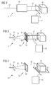
- Fig. 3 shows a beam-shaping device 35, which comprises a collimator 47 with a linear opening 49.
- a scattering device 51 is arranged in the beam path in front of this collimator 47.
- An incoming particle beam 33, which strikes the scattering device 51 is widened in a cone shape.
- the cone-shaped expanded particle jet 53 passes through the linear opening 49 of the collimator 47, the particle beam is given a linear cross-sectional profile 39.
- the collimator 47 shown here has an adjusting device 55 for changing the geometry of the linear opening 49 of the collimator 47.
- an adjustment device 55 having a plurality of teeth that can be slid into the linear opening 49 of the collimator 47.
- the length of the linear opening 49 of the collimator 47 can be limited and variably adjusted.
- the linear opening 49 of the collimator 47 in the middle can be interrupted, so that the shaped particle beam 37 has a broken line-shaped cross-sectional profile 39. This makes it possible, in a simple manner, also to achieve target volumes "with a hole", i. So to irradiate target volumes with a toroidal shape.
- the geometry of the linear opening 49 of the collimator 47 can be changed with the adjustment device 55.
- the changes can be controlled and implemented, for example, by an irradiation plan in which the geometry of the target volume 41 is stored.
- the scanning is carried out by the fact that the linear opening 49 of the collimator 47 is arranged perpendicular to the beam path of the particle beam slidably. This can be done, for example, that the entire collimator 47 perpendicular to the beam path the particle beam is slidably mounted.
- the position of the linear opening 49 of the collimator 47 in the beam path is controlled by the control device 43 for changing the relative position.
- the control device 43 can also simultaneously take over the control of the setting device 55 for changing the geometry of the linear opening 49.
- Fig. 4 shows a similar beam-shaping device 35 as in FIG Fig. 3 ,
- the adjusting device for changing the geometry of the linear opening 49 is not shown.
- particle beam application device 31 allows scanning of the shaped particle beam 37 over the target volume 41 characterized in that the target volume 41 is movably mounted via a positioning device 57 during an irradiation process.
- the shaped particle beam 37 scans with the linear cross-sectional profile 39 over the target volume 41.
- control device 43 for changing the relative position between particle beam and target volume is designed such that a control signal for the positioning device 57 for the target volume 41 can be output with it.
- the positioning device 57 may in particular be a component of the particle beam application device 31.
- Fig. 5 shows another embodiment of the particle beam application device 31.
- the beam-shaping device 35 comprises a magnet system 59 with which an oscillating magnetic field can be generated.
- a particle beam 33 entering this magnet system 59 with a point-shaped cross-sectional profile is deflected in a rapidly oscillating manner in a direction which is essentially perpendicular to the beam path direction. Due to the rapid oscillation occurs from the magnet system 59 a shaped particle beam 37 having a substantially line-shaped cross-sectional profile 39.
- the magnet system 59 is controlled by a magnetic system control device 61 with which, for example, an offset and / or an amplitude and / or a frequency of the oscillating magnetic field can be adjusted.
- these parameters are variably adjustable during an irradiation process. In this way, it can be achieved that the shaped particle beam 37 can be adapted exactly to the shape of the target volume 41 during a scanning process.
- the particle beam application device 31 has an electromagnetic deflection device 63.
- This deflection device 63 is arranged behind the magnet system 59 in the course of the beam.
- a shaped particle beam 37 passing through this deflector 63 is deflected out of its zero position by the magnetic field generated by the deflector 63.
- the electromagnetic deflecting device 63 is controlled by the relative position changing control device 43.
- Fig. 6 shows a plan view of an advantageous development of the particle beam application device 31, with which a guided through the particle beam application device 31 particle beam can be cleaned of scattered radiation.
- the particle beam with the line-shaped cross-sectional profile is generated by a scattering device 51 for widening an incoming particle beam 33 and a collimator 47 having a linear opening 49, stray radiation is produced.
- This scattered radiation "contaminates" the particle beam, which now has particles which have an undesired mass-to-charge ratio or whose energy deviates from a desired energy.
- the shaped one Particle beam 37 is now passed through a dipole magnet 65 and deflected by this dipole magnet 65.
- the unwanted particles of the shaped particle beam 37 experience a different deflection, compared with the desired particle of the particle beam.
- a particle jet 67 emerging from the dipole magnet 65 therefore consists of particles whose energy or their mass-to-charge ratio is significantly more uniform than the shaped particle beam 37 entering the dipole magnet 65, which is contaminated with scattered radiation.
- a second collimator 69 may be arranged with a linear opening through which the exiting particle beam 67 passes.
- the second collimator 69 is positioned such that particles with the desired energy or with the desired mass-to-charge ratio pass through the linear opening of the second collimator 69. This results in a further filtering of particles having an undesirable energy or an undesirable mass-to-charge ratio. Namely, such particles have been deflected differently by the dipole magnet 65 so that they do not pass through the linear opening of the second collimator 69.
- the linear opening of the first collimator 47 in the particle beam is e.g. is moved during an irradiation process, a movement of the linear opening of the second collimator 69 in the beam path takes place in a corresponding manner.
- the coordinated movement of the two collimators with respect to each other can be controlled by the relative position changing control device 43.
- a depth modulation device 71 for influencing the particle beam energy is arranged in the beam path.
- the energy of the Particles of the particle beam and thus the penetration depth of the particle beam are modulated in the target volume.
- a so-called modulator wheel or a so-called ridge filter can be used for influencing the particle beam energy.
- it is possible to adjust the energy of the particles of the particle beam for example by controlling the accelerator with which the particles are accelerated.
- the depth modulation device 71 is arranged after the dipole magnet 65 and before the second collimator 69.
- other arrangements of the depth modulation device are conceivable, for example after the second collimator 69 or elsewhere.
- Fig. 7 shows a schematic overview of the method steps of an embodiment of the method for guiding a particle beam.
- a first step 81 the cross-sectional profile of a particle beam is shaped such that the particle beam has a line-shaped cross-sectional profile.
- the particle beam fanned out first and then be shaped cross-sectional profile.
- the course of the particle beam is variably changed in a direction which is perpendicular to the beam path direction of the particle beam and in particular perpendicular to the linear course of the line-shaped cross-sectional profile.
- the particle beam can be cleaned of stray radiation in an optional, third step 85 by guiding the particle beam through a further, second magnetic field and deflecting it in its direction.
- the particle beam can be redone in an optional, fourth step 87 in its cross-sectional profile in particular be formed by a collimator.
- a particle beam shaped in this way can be used for various purposes, for example for research purposes, for the irradiation of target volumes, etc.
Landscapes
- Physics & Mathematics (AREA)
- Engineering & Computer Science (AREA)
- Spectroscopy & Molecular Physics (AREA)
- General Engineering & Computer Science (AREA)
- High Energy & Nuclear Physics (AREA)
- Health & Medical Sciences (AREA)
- Biomedical Technology (AREA)
- Nuclear Medicine, Radiotherapy & Molecular Imaging (AREA)
- Pathology (AREA)
- Radiology & Medical Imaging (AREA)
- Life Sciences & Earth Sciences (AREA)
- Animal Behavior & Ethology (AREA)
- General Health & Medical Sciences (AREA)
- Public Health (AREA)
- Veterinary Medicine (AREA)
- Radiation-Therapy Devices (AREA)
- Welding Or Cutting Using Electron Beams (AREA)
Applications Claiming Priority (2)
| Application Number | Priority Date | Filing Date | Title |
|---|---|---|---|
| US96134807P | 2007-07-20 | 2007-07-20 | |
| DE102007033894A DE102007033894B3 (de) | 2007-07-20 | 2007-07-20 | Partikelstrahlapplikationsvorrichtung, Bestrahlungsvorrichtung sowie Verfahren zur Führung eines Partikelstrahls |
Publications (3)
| Publication Number | Publication Date |
|---|---|
| EP2016979A2 true EP2016979A2 (fr) | 2009-01-21 |
| EP2016979A3 EP2016979A3 (fr) | 2009-06-24 |
| EP2016979B1 EP2016979B1 (fr) | 2011-06-08 |
Family
ID=39942378
Family Applications (1)
| Application Number | Title | Priority Date | Filing Date |
|---|---|---|---|
| EP08104473A Not-in-force EP2016979B1 (fr) | 2007-07-20 | 2008-06-19 | Dispositif d'application par rayon de particules, dispositif de rayonnement et procédé de guidage d'un rayon de particules |
Country Status (4)
| Country | Link |
|---|---|
| US (1) | US20090020711A1 (fr) |
| EP (1) | EP2016979B1 (fr) |
| AT (1) | ATE511887T1 (fr) |
| DE (1) | DE102007033894B3 (fr) |
Families Citing this family (10)
| Publication number | Priority date | Publication date | Assignee | Title |
|---|---|---|---|---|
| DE102007033895A1 (de) * | 2007-07-20 | 2009-01-29 | Siemens Ag | Partikelstrahlapplikationsvorrichtung, Bestrahlungsvorrichtung sowie Verfahren zur Führung eines Partikelstrahls |
| ES2605031T3 (es) * | 2009-10-23 | 2017-03-10 | Ion Beam Applications | Pórtico que comprende un analizador de haz para su uso en terapia de partículas |
| US10751554B2 (en) * | 2010-04-16 | 2020-08-25 | Scott Penfold | Multiple treatment beam type cancer therapy apparatus and method of use thereof |
| EP2800605B2 (fr) | 2012-01-03 | 2022-11-09 | BeneSol, Inc. | Appareil de photothérapie pour rayonnement uvb concentré et synthèse de vitamine d et systèmes associés |
| EP3964260A1 (fr) * | 2016-10-03 | 2022-03-09 | BeneSol, Inc. | Systèmes de photothérapie comprenant des caractéristiques de diffusion et de collimation et technologie associée |
| WO2019118773A1 (fr) | 2017-12-15 | 2019-06-20 | Benesol, Inc. | Systèmes de dosage dynamique pour la photothérapie et dispositifs, systèmes et procédés associés |
| WO2020021315A1 (fr) * | 2018-07-27 | 2020-01-30 | Universidad De La Frontera | Dispositif adaptable à des équipments de radiothérapie externe qui concentre la dose dans la cible à foyer variable |
| JP7378326B2 (ja) * | 2020-03-18 | 2023-11-13 | 住友重機械工業株式会社 | 粒子線装置 |
| CA3227880A1 (fr) * | 2021-08-05 | 2023-02-09 | Marios SOTIROPOULOS | Dispositif dynamique de balayage permettant la production de minifaisceaux |
| JP7817965B2 (ja) * | 2023-03-22 | 2026-02-19 | 株式会社日立製作所 | 粒子線照射システム及び粒子線照射方法 |
Family Cites Families (15)
| Publication number | Priority date | Publication date | Assignee | Title |
|---|---|---|---|---|
| US2814728A (en) * | 1955-07-19 | 1957-11-26 | Jr Alexander S Langsdorf | Ion beam collimator |
| US5311028A (en) * | 1990-08-29 | 1994-05-10 | Nissin Electric Co., Ltd. | System and method for producing oscillating magnetic fields in working gaps useful for irradiating a surface with atomic and molecular ions |
| US5668371A (en) * | 1995-06-06 | 1997-09-16 | Wisconsin Alumni Research Foundation | Method and apparatus for proton therapy |
| EP0986070B1 (fr) * | 1998-09-11 | 2010-06-30 | GSI Helmholtzzentrum für Schwerionenforschung GmbH | Dispositif de thérapie par faisceau d'ions et procédé d'exploitation du dispositif |
| JP4118433B2 (ja) * | 1999-01-20 | 2008-07-16 | 三菱電機株式会社 | 荷電粒子線照射装置及びその装置に用いるエネルギーコンペンセータ、並びに荷電粒子線照射方法 |
| DE19907098A1 (de) * | 1999-02-19 | 2000-08-24 | Schwerionenforsch Gmbh | Ionenstrahl-Abtastsystem und Verfahren zum Betrieb des Systems |
| DE10057824A1 (de) * | 2000-11-21 | 2002-06-06 | Schwerionenforsch Gmbh | Vorrichtung und Verfahren zur Anpassung einer Ionenstrahlfleckgröße in der Tumorbestrahlung |
| US20030001110A1 (en) * | 2000-12-28 | 2003-01-02 | Harald Enge | System and method for amplifying an angle of divergence of a scanned ion beam |
| DE10323654A1 (de) * | 2003-05-26 | 2004-12-30 | GSI Gesellschaft für Schwerionenforschung mbH | Energiefiltereinrichtung |
| US7675050B2 (en) * | 2006-06-12 | 2010-03-09 | Advanced Ion Beam Technology, Inc. | Apparatus and method for ion beam implantation using ribbon and spot beams |
| EP1752992A1 (fr) * | 2005-08-12 | 2007-02-14 | Siemens Aktiengesellschaft | Dispositif d'adaptation d'un paramètre de faisceau à particules d'un faisceau à particules dans un accélérateur de particules et accélérateur de particules comprenant un tél dispositif |
| ES2730108T3 (es) * | 2005-11-18 | 2019-11-08 | Mevion Medical Systems Inc | Radioterapia de partículas cargadas |
| US7902530B1 (en) * | 2006-04-06 | 2011-03-08 | Velayudhan Sahadevan | Multiple medical accelerators and a kV-CT incorporated radiation therapy device and semi-automated custom reshapeable blocks for all field synchronous image guided 3-D-conformal-intensity modulated radiation therapy |
| JP4828305B2 (ja) * | 2006-05-30 | 2011-11-30 | 株式会社Sen | 静電式ビーム偏向走査装置及びビーム偏向走査方法 |
| WO2008106488A1 (fr) * | 2007-02-27 | 2008-09-04 | Wisconsin Alumni Research Foundation | Système de radiothérapie par ions comprenant un dispositif magnétique de formation de faisceau en éventail |
-
2007
- 2007-07-20 DE DE102007033894A patent/DE102007033894B3/de not_active Expired - Fee Related
-
2008
- 2008-06-19 EP EP08104473A patent/EP2016979B1/fr not_active Not-in-force
- 2008-06-19 AT AT08104473T patent/ATE511887T1/de active
- 2008-07-17 US US12/218,724 patent/US20090020711A1/en not_active Abandoned
Non-Patent Citations (1)
| Title |
|---|
| None |
Also Published As
| Publication number | Publication date |
|---|---|
| EP2016979A3 (fr) | 2009-06-24 |
| US20090020711A1 (en) | 2009-01-22 |
| DE102007033894B3 (de) | 2008-12-11 |
| EP2016979B1 (fr) | 2011-06-08 |
| ATE511887T1 (de) | 2011-06-15 |
Similar Documents
| Publication | Publication Date | Title |
|---|---|---|
| EP2016979B1 (fr) | Dispositif d'application par rayon de particules, dispositif de rayonnement et procédé de guidage d'un rayon de particules | |
| EP2022534B1 (fr) | Dispositif de commande destiné à commander un processus de rayonnement, installation de thérapie à particules ainsi que procédé de rayonnement d'un volume cible | |
| DE102007054919B4 (de) | Schnelle Regelung der Reichweite von hochenergetischen Ionenstrahlen für Präzisionsbestrahlungen von bewegten Zielvolumina | |
| DE102008010958B4 (de) | Konformales Mehrschicht-Strahlentherapiesystem und dieses verwendende Teilchenstrahl-Therapievorrichtung | |
| DE60312597T2 (de) | System zur Bestrahlung mit geladenen Teilchen | |
| EP2100641B1 (fr) | Installation de thérapie à particules et procédé destiné à la modulation d'un rayon de particules produit dans un accélérateur | |
| DE102009040031B4 (de) | Lasergetriebene Teilchenstrahl-Bestrahlungsvorrichtung sowie -Verfahren | |
| DE69932537T2 (de) | Vorrichtung zur behandlung eines zielvolumens durch einen teilchenstrahl | |
| DE102009032275A1 (de) | Beschleunigeranlage und Verfahren zur Einstellung einer Partikelenergie | |
| EP1905481B1 (fr) | Installation de thérapie à particules pour la thérapie à particule d'un volume cible soumis à un mouvement | |
| DE3018914C2 (de) | Vorrichtung zum Bestrahlen eines begrenzten Volumens im Innern eines Körpers mit einer Strahlungsquelle | |
| EP1987859A2 (fr) | Installation de thérapie à particules | |
| DE3805123A1 (de) | Verfahren zur bestrahlung eines grossflaechigen feldes mit einem strahl aus geladenen teilchen und vorrichtung zur durchfuehrung eines solchen verfahrens | |
| EP2248144B1 (fr) | Système de thérapie par particules | |
| DE102008023350A1 (de) | Teilchenbestrahlungsvorrichtung, Teilchenbestrahlungsverfahren und Teilchenstrahlbehandlungssystem | |
| EP1482519B1 (fr) | Dispositif de filtrage en énergie | |
| DE2515406A1 (de) | Absorptionskoerper | |
| EP2539903A1 (fr) | Dispositif et procédé d'exposition à un rayonnement pour le dépôt d'une dose dans un volume cible | |
| DE102016225798B4 (de) | Einrichtung zum Bestrahlen eines Gewebes zur Strahlentherapie mit aufgeweiteten Teilchenstrahlen | |
| EP2528064A1 (fr) | Modulateurs de distance multiples | |
| DE10041473B4 (de) | Vorrichtung zur Bestrahlung von Gewebe | |
| EP2652746A1 (fr) | Filtre d'énergie chromatique | |
| DE2317748A1 (de) | Ablenkvorrichtung zur umformung eines schmalen strahlenbuendels energiereicher elektronen in ein breites strahlenbuendel gewuenschter querschnittsflaeche | |
| EP2016978A2 (fr) | Dispositif d'application par rayon de particules, dispositif de rayonnement et procédé de guidage d'un rayon de particule | |
| DE2164207C3 (de) | Einrichtung zur Bestrahlung mit energiereichen Elektronen |
Legal Events
| Date | Code | Title | Description |
|---|---|---|---|
| PUAI | Public reference made under article 153(3) epc to a published international application that has entered the european phase |
Free format text: ORIGINAL CODE: 0009012 |
|
| AK | Designated contracting states |
Kind code of ref document: A2 Designated state(s): AT BE BG CH CY CZ DE DK EE ES FI FR GB GR HR HU IE IS IT LI LT LU LV MC MT NL NO PL PT RO SE SI SK TR |
|
| AX | Request for extension of the european patent |
Extension state: AL BA MK RS |
|
| PUAL | Search report despatched |
Free format text: ORIGINAL CODE: 0009013 |
|
| AK | Designated contracting states |
Kind code of ref document: A3 Designated state(s): AT BE BG CH CY CZ DE DK EE ES FI FR GB GR HR HU IE IS IT LI LT LU LV MC MT NL NO PL PT RO SE SI SK TR |
|
| AX | Request for extension of the european patent |
Extension state: AL BA MK RS |
|
| 17P | Request for examination filed |
Effective date: 20091207 |
|
| AKX | Designation fees paid |
Designated state(s): AT BE BG CH CY CZ DE DK EE ES FI FR GB GR HR HU IE IS IT LI LT LU LV MC MT NL NO PL PT RO SE SI SK TR |
|
| 17Q | First examination report despatched |
Effective date: 20100608 |
|
| GRAP | Despatch of communication of intention to grant a patent |
Free format text: ORIGINAL CODE: EPIDOSNIGR1 |
|
| GRAS | Grant fee paid |
Free format text: ORIGINAL CODE: EPIDOSNIGR3 |
|
| GRAA | (expected) grant |
Free format text: ORIGINAL CODE: 0009210 |
|
| AK | Designated contracting states |
Kind code of ref document: B1 Designated state(s): AT BE BG CH CY CZ DE DK EE ES FI FR GB GR HR HU IE IS IT LI LT LU LV MC MT NL NO PL PT RO SE SI SK TR |
|
| REG | Reference to a national code |
Ref country code: GB Ref legal event code: FG4D Free format text: NOT ENGLISH |
|
| REG | Reference to a national code |
Ref country code: CH Ref legal event code: EP Ref country code: CH Ref legal event code: NV Representative=s name: SIEMENS SCHWEIZ AG |
|
| REG | Reference to a national code |
Ref country code: IE Ref legal event code: FG4D Free format text: LANGUAGE OF EP DOCUMENT: GERMAN |
|
| REG | Reference to a national code |
Ref country code: DE Ref legal event code: R096 Ref document number: 502008003770 Country of ref document: DE Effective date: 20110721 |
|
| REG | Reference to a national code |
Ref country code: NL Ref legal event code: VDEP Effective date: 20110608 |
|
| PG25 | Lapsed in a contracting state [announced via postgrant information from national office to epo] |
Ref country code: HR Free format text: LAPSE BECAUSE OF FAILURE TO SUBMIT A TRANSLATION OF THE DESCRIPTION OR TO PAY THE FEE WITHIN THE PRESCRIBED TIME-LIMIT Effective date: 20110608 Ref country code: SE Free format text: LAPSE BECAUSE OF FAILURE TO SUBMIT A TRANSLATION OF THE DESCRIPTION OR TO PAY THE FEE WITHIN THE PRESCRIBED TIME-LIMIT Effective date: 20110608 Ref country code: NO Free format text: LAPSE BECAUSE OF FAILURE TO SUBMIT A TRANSLATION OF THE DESCRIPTION OR TO PAY THE FEE WITHIN THE PRESCRIBED TIME-LIMIT Effective date: 20110908 Ref country code: LT Free format text: LAPSE BECAUSE OF FAILURE TO SUBMIT A TRANSLATION OF THE DESCRIPTION OR TO PAY THE FEE WITHIN THE PRESCRIBED TIME-LIMIT Effective date: 20110608 |
|
| PG25 | Lapsed in a contracting state [announced via postgrant information from national office to epo] |
Ref country code: GR Free format text: LAPSE BECAUSE OF FAILURE TO SUBMIT A TRANSLATION OF THE DESCRIPTION OR TO PAY THE FEE WITHIN THE PRESCRIBED TIME-LIMIT Effective date: 20110909 Ref country code: ES Free format text: LAPSE BECAUSE OF FAILURE TO SUBMIT A TRANSLATION OF THE DESCRIPTION OR TO PAY THE FEE WITHIN THE PRESCRIBED TIME-LIMIT Effective date: 20110919 Ref country code: FI Free format text: LAPSE BECAUSE OF FAILURE TO SUBMIT A TRANSLATION OF THE DESCRIPTION OR TO PAY THE FEE WITHIN THE PRESCRIBED TIME-LIMIT Effective date: 20110608 Ref country code: SI Free format text: LAPSE BECAUSE OF FAILURE TO SUBMIT A TRANSLATION OF THE DESCRIPTION OR TO PAY THE FEE WITHIN THE PRESCRIBED TIME-LIMIT Effective date: 20110608 Ref country code: CY Free format text: LAPSE BECAUSE OF FAILURE TO SUBMIT A TRANSLATION OF THE DESCRIPTION OR TO PAY THE FEE WITHIN THE PRESCRIBED TIME-LIMIT Effective date: 20110608 Ref country code: LV Free format text: LAPSE BECAUSE OF FAILURE TO SUBMIT A TRANSLATION OF THE DESCRIPTION OR TO PAY THE FEE WITHIN THE PRESCRIBED TIME-LIMIT Effective date: 20110608 |
|
| PG25 | Lapsed in a contracting state [announced via postgrant information from national office to epo] |
Ref country code: MT Free format text: LAPSE BECAUSE OF FAILURE TO SUBMIT A TRANSLATION OF THE DESCRIPTION OR TO PAY THE FEE WITHIN THE PRESCRIBED TIME-LIMIT Effective date: 20110608 Ref country code: NL Free format text: LAPSE BECAUSE OF FAILURE TO SUBMIT A TRANSLATION OF THE DESCRIPTION OR TO PAY THE FEE WITHIN THE PRESCRIBED TIME-LIMIT Effective date: 20110608 |
|
| BERE | Be: lapsed |
Owner name: SIEMENS A.G. Effective date: 20110630 |
|
| REG | Reference to a national code |
Ref country code: IE Ref legal event code: FD4D |
|
| PG25 | Lapsed in a contracting state [announced via postgrant information from national office to epo] |
Ref country code: EE Free format text: LAPSE BECAUSE OF FAILURE TO SUBMIT A TRANSLATION OF THE DESCRIPTION OR TO PAY THE FEE WITHIN THE PRESCRIBED TIME-LIMIT Effective date: 20110608 Ref country code: IS Free format text: LAPSE BECAUSE OF FAILURE TO SUBMIT A TRANSLATION OF THE DESCRIPTION OR TO PAY THE FEE WITHIN THE PRESCRIBED TIME-LIMIT Effective date: 20111008 Ref country code: CZ Free format text: LAPSE BECAUSE OF FAILURE TO SUBMIT A TRANSLATION OF THE DESCRIPTION OR TO PAY THE FEE WITHIN THE PRESCRIBED TIME-LIMIT Effective date: 20110608 Ref country code: IE Free format text: LAPSE BECAUSE OF FAILURE TO SUBMIT A TRANSLATION OF THE DESCRIPTION OR TO PAY THE FEE WITHIN THE PRESCRIBED TIME-LIMIT Effective date: 20110608 Ref country code: PT Free format text: LAPSE BECAUSE OF FAILURE TO SUBMIT A TRANSLATION OF THE DESCRIPTION OR TO PAY THE FEE WITHIN THE PRESCRIBED TIME-LIMIT Effective date: 20111010 |
|
| PG25 | Lapsed in a contracting state [announced via postgrant information from national office to epo] |
Ref country code: SK Free format text: LAPSE BECAUSE OF FAILURE TO SUBMIT A TRANSLATION OF THE DESCRIPTION OR TO PAY THE FEE WITHIN THE PRESCRIBED TIME-LIMIT Effective date: 20110608 Ref country code: RO Free format text: LAPSE BECAUSE OF FAILURE TO SUBMIT A TRANSLATION OF THE DESCRIPTION OR TO PAY THE FEE WITHIN THE PRESCRIBED TIME-LIMIT Effective date: 20110608 Ref country code: PL Free format text: LAPSE BECAUSE OF FAILURE TO SUBMIT A TRANSLATION OF THE DESCRIPTION OR TO PAY THE FEE WITHIN THE PRESCRIBED TIME-LIMIT Effective date: 20110608 |
|
| PG25 | Lapsed in a contracting state [announced via postgrant information from national office to epo] |
Ref country code: BE Free format text: LAPSE BECAUSE OF NON-PAYMENT OF DUE FEES Effective date: 20110630 |
|
| PLBE | No opposition filed within time limit |
Free format text: ORIGINAL CODE: 0009261 |
|
| STAA | Information on the status of an ep patent application or granted ep patent |
Free format text: STATUS: NO OPPOSITION FILED WITHIN TIME LIMIT |
|
| 26N | No opposition filed |
Effective date: 20120309 |
|
| PG25 | Lapsed in a contracting state [announced via postgrant information from national office to epo] |
Ref country code: IT Free format text: LAPSE BECAUSE OF FAILURE TO SUBMIT A TRANSLATION OF THE DESCRIPTION OR TO PAY THE FEE WITHIN THE PRESCRIBED TIME-LIMIT Effective date: 20110608 |
|
| PG25 | Lapsed in a contracting state [announced via postgrant information from national office to epo] |
Ref country code: DK Free format text: LAPSE BECAUSE OF FAILURE TO SUBMIT A TRANSLATION OF THE DESCRIPTION OR TO PAY THE FEE WITHIN THE PRESCRIBED TIME-LIMIT Effective date: 20110608 |
|
| REG | Reference to a national code |
Ref country code: DE Ref legal event code: R097 Ref document number: 502008003770 Country of ref document: DE Effective date: 20120309 |
|
| GBPC | Gb: european patent ceased through non-payment of renewal fee |
Effective date: 20120619 |
|
| PG25 | Lapsed in a contracting state [announced via postgrant information from national office to epo] |
Ref country code: MC Free format text: LAPSE BECAUSE OF NON-PAYMENT OF DUE FEES Effective date: 20110630 Ref country code: GB Free format text: LAPSE BECAUSE OF NON-PAYMENT OF DUE FEES Effective date: 20120619 |
|
| PG25 | Lapsed in a contracting state [announced via postgrant information from national office to epo] |
Ref country code: LU Free format text: LAPSE BECAUSE OF NON-PAYMENT OF DUE FEES Effective date: 20110619 |
|
| PG25 | Lapsed in a contracting state [announced via postgrant information from national office to epo] |
Ref country code: BG Free format text: LAPSE BECAUSE OF FAILURE TO SUBMIT A TRANSLATION OF THE DESCRIPTION OR TO PAY THE FEE WITHIN THE PRESCRIBED TIME-LIMIT Effective date: 20110908 |
|
| PG25 | Lapsed in a contracting state [announced via postgrant information from national office to epo] |
Ref country code: TR Free format text: LAPSE BECAUSE OF FAILURE TO SUBMIT A TRANSLATION OF THE DESCRIPTION OR TO PAY THE FEE WITHIN THE PRESCRIBED TIME-LIMIT Effective date: 20110608 |
|
| PG25 | Lapsed in a contracting state [announced via postgrant information from national office to epo] |
Ref country code: HU Free format text: LAPSE BECAUSE OF FAILURE TO SUBMIT A TRANSLATION OF THE DESCRIPTION OR TO PAY THE FEE WITHIN THE PRESCRIBED TIME-LIMIT Effective date: 20110608 |
|
| REG | Reference to a national code |
Ref country code: DE Ref legal event code: R081 Ref document number: 502008003770 Country of ref document: DE Owner name: SIEMENS HEALTHCARE GMBH, DE Free format text: FORMER OWNER: SIEMENS AKTIENGESELLSCHAFT, 80333 MUENCHEN, DE |
|
| REG | Reference to a national code |
Ref country code: FR Ref legal event code: PLFP Year of fee payment: 9 |
|
| REG | Reference to a national code |
Ref country code: FR Ref legal event code: PLFP Year of fee payment: 10 |
|
| PGFP | Annual fee paid to national office [announced via postgrant information from national office to epo] |
Ref country code: FR Payment date: 20170623 Year of fee payment: 10 |
|
| PGFP | Annual fee paid to national office [announced via postgrant information from national office to epo] |
Ref country code: AT Payment date: 20170504 Year of fee payment: 10 |
|
| REG | Reference to a national code |
Ref country code: CH Ref legal event code: PCOW Free format text: NEW ADDRESS: WERNER-VON-SIEMENS-STRASSE 1, 80333 MUENCHEN (DE) |
|
| PGFP | Annual fee paid to national office [announced via postgrant information from national office to epo] |
Ref country code: CH Payment date: 20170904 Year of fee payment: 10 Ref country code: DE Payment date: 20170821 Year of fee payment: 10 |
|
| REG | Reference to a national code |
Ref country code: DE Ref legal event code: R119 Ref document number: 502008003770 Country of ref document: DE |
|
| REG | Reference to a national code |
Ref country code: CH Ref legal event code: PL |
|
| REG | Reference to a national code |
Ref country code: AT Ref legal event code: MM01 Ref document number: 511887 Country of ref document: AT Kind code of ref document: T Effective date: 20180619 |
|
| PG25 | Lapsed in a contracting state [announced via postgrant information from national office to epo] |
Ref country code: DE Free format text: LAPSE BECAUSE OF NON-PAYMENT OF DUE FEES Effective date: 20190101 Ref country code: FR Free format text: LAPSE BECAUSE OF NON-PAYMENT OF DUE FEES Effective date: 20180630 Ref country code: LI Free format text: LAPSE BECAUSE OF NON-PAYMENT OF DUE FEES Effective date: 20180630 Ref country code: CH Free format text: LAPSE BECAUSE OF NON-PAYMENT OF DUE FEES Effective date: 20180630 Ref country code: AT Free format text: LAPSE BECAUSE OF NON-PAYMENT OF DUE FEES Effective date: 20180619 |