EP2017010A2 - Tête de distribution pour un pistolet pulvérisateur - Google Patents
Tête de distribution pour un pistolet pulvérisateur Download PDFInfo
- Publication number
- EP2017010A2 EP2017010A2 EP08011130A EP08011130A EP2017010A2 EP 2017010 A2 EP2017010 A2 EP 2017010A2 EP 08011130 A EP08011130 A EP 08011130A EP 08011130 A EP08011130 A EP 08011130A EP 2017010 A2 EP2017010 A2 EP 2017010A2
- Authority
- EP
- European Patent Office
- Prior art keywords
- air
- atomizing
- atomizing head
- air cap
- head according
- Prior art date
- Legal status (The legal status is an assumption and is not a legal conclusion. Google has not performed a legal analysis and makes no representation as to the accuracy of the status listed.)
- Granted
Links
Images


Classifications
-
- B—PERFORMING OPERATIONS; TRANSPORTING
- B05—SPRAYING OR ATOMISING IN GENERAL; APPLYING FLUENT MATERIALS TO SURFACES, IN GENERAL
- B05B—SPRAYING APPARATUS; ATOMISING APPARATUS; NOZZLES
- B05B7/00—Spraying apparatus for discharge of liquids or other fluent materials from two or more sources, e.g. of liquid and air, of powder and gas
- B05B7/02—Spray pistols; Apparatus for discharge
- B05B7/08—Spray pistols; Apparatus for discharge with separate outlet orifices, e.g. to form parallel jets, i.e. the axis of the jets being parallel, to form intersecting jets, i.e. the axis of the jets converging but not necessarily intersecting at a point
- B05B7/0807—Spray pistols; Apparatus for discharge with separate outlet orifices, e.g. to form parallel jets, i.e. the axis of the jets being parallel, to form intersecting jets, i.e. the axis of the jets converging but not necessarily intersecting at a point to form intersecting jets
- B05B7/0815—Spray pistols; Apparatus for discharge with separate outlet orifices, e.g. to form parallel jets, i.e. the axis of the jets being parallel, to form intersecting jets, i.e. the axis of the jets converging but not necessarily intersecting at a point to form intersecting jets with at least one gas jet intersecting a jet constituted by a liquid or a mixture containing a liquid for controlling the shape of the latter
Definitions
- the invention relates to a Zerstäuberkopf for a spray gun for pneumatic spraying of paint, paint or the like liquids and a spray gun with such a Zerstäuberkopf.
- a compressed air jet In the pneumatic atomization of liquids, which are used for example in paint shops, a compressed air jet is used to atomize a liquid jet. For this purpose, a compressed air jet with high energy is necessary.
- a disadvantage of conventional pneumatic atomization methods is that they require a large amount of compressed air and a very strong jet of compressed air and atomized paint is produced. Such a jet carries a lot of color with it, which is not deposited on the object to be coated, but dispersed with strong turbulence in the ambient air.
- From the DE 28 11 436 C2 is a method for pneumatic atomization of emerging from a paint nozzle, fan-shaped liquid jet known.
- the atomization is carried out in this known method by means of fan-shaped arranged around the ink jet compressed air jets, which are directed to the ink jet and have a sufficiently high energy for the color sputtering.
- This air pressures of 1 to 4 bar and an air flow of 3 to 9 m 3 / h can be achieved.
- Other compressed air jets are directed against the conical outer surface of the paint nozzle and cause an air curtain, which envelops the jet of color and should prevent a "kickback" of the paint on the nozzle.
- an atomizing head for spray guns of the type mentioned in which a pneumatic atomization of a jet of color occurs, which emerges from a paint nozzle with a slot-shaped nozzle opening.
- a pneumatic atomization of a jet of color occurs, which emerges from a paint nozzle with a slot-shaped nozzle opening.
- several compressed air channels are provided here, which are arranged laterally on the slot-shaped nozzle opening and are fed by a common compressed air system.
- the additional jets of air emerge from opposing projections of the air cap, which are often referred to as "horns.” Typically, these horns protrude by a height that is about 30% of the diameter of the air cap from the face of the air cap.
- the protruding from the end face of the air cap horns are designed such that the additional air jets are directed towards each other and to the spray jet so as to form the flat or oval beam by the collision with the spray jet.
- the additional air jets are often called so-called “Horn air” or “mold air”. Further air jets, which emerge from the air cap substantially parallel to the axis of the spray jet, serve to regulate the irregularly deformed spray jet.
- Similar atomizing heads with a circular paint nozzle, with a surrounding the paint nozzle compressed air ring nozzle for atomizing the color and with Hom Kunststoffdüsen, which are arranged on horns, are also from the DE 90 01 265 U1 and the DE 689 24 079 T2 known.
- additional openings for so-called fan air jets are provided between the annular nozzle and the horns, which are intended to effect a regulation of the spray jet by slowing down and fanning the shaping air jets before they impinge on the spray jet.
- the invention has for its object to improve a Zerstäuberkopf the above type in such a way that the overspray and thus the consumption of the liquid applied by the Zerstäuberkopf can be reduced.
- the atomizer head comprises a circular fluid nozzle and an air cap with a centrally arranged bore for receiving the fluid nozzle.
- the air cap is provided with a plurality of nozzles for atomizing the liquid and for shaping the spray jet.
- atomizing air nozzles through which compressed air is supplied for atomizing the liquid emerging from the ink nozzle, are arranged annularly around the liquid nozzle.
- the shaping air homing air
- the end face of the air cap is at least substantially planar and flat.
- the mold air is guided over shaping air nozzles which open obliquely into this flat end face onto the spray jet.
- the atomizing air jets and the shaping air jets are thus arranged approximately in the same plane.
- the substantially flat and planar design of the end face of the air cap does not exclude that are formed in these recesses and / or openings for the nozzles.
- a particular circumferential bead may be provided or the end face may be slightly concave.
- the optionally projecting edge region of the end face protrudes less than 10%, in particular less than about 5%, of the diameter of the air cap relative to a central region of the air cap located near the axis of rotation.
- the overspray can be up to 30% compared to a conventional Atomizer head can be reduced.
- the paint consumption is reduced by up to 30%, which on the one hand causes a saving of material and on the other hand leads to less contamination of equipment and aggregates. In this way, longer service life can be achieved and savings in cleaning can be achieved.
- the paint consumption can be reduced by about 20%.
- the Zerstäuberkopf invention is characterized by a significantly lower cleaning costs.
- the cleaning device 'Vapo Gun Cleaner' Industra industrial equipment machines + parts GmbH
- the detergent consumption can be reduced to 2 to 20 ml per rinse. Even with other cleaning systems, a more economical cleaning is possible.
- the shaping air nozzles of the spray jet is uniformly shaped, whereby the so-called pulsation or flutter of the spray jet, which leads to a cloud formation in the paint job is significantly reduced.
- the wetting disorders occurring in conventional paint application systems and the uneven layer thickness distributions of the applied paint are effectively prevented. Consequently, the use of the atomizer head according to the invention leads to a more uniform spray pattern, a more uniform wetting and a more uniform coating thickness distribution of the applied paint or the like than in conventional paint application systems.
- the atomizer head according to the invention is particularly suitable for robot-controlled paint application on Fährzeugkarosserien, for example, for the robot-guided Falzlackierung of Monfalzen, hoods or other interior applications. Furthermore, larger body surfaces are first electrostatically coated with bells with a base coat and then with A spray gun with pneumatically atomized liquid jet repainted (Air-Außensmoked). In addition to a flutter- and cloud-free basecoat application for folds and non-skinned varnish layers, an error-free substrate wetting is achieved here - even with thin basecoat layers. Even bright metallic shades can be painted cloud-free in this way. In this way it is possible to reduce the costs for reworking with the atomizing head according to the invention.
- the atomizer head according to the invention is also particularly suitable for use in the supply industry, in which also components for later installation in, for example, vehicles are painted.
- the air caps are made of brass or aluminum and then galvanized to protect their surface, usually nickel-plated or chrome-plated. Galvanization produces different layer thicknesses, in particular at the edges of the air outlet bores. In some cases, even miniature burrs, which give each air cap their individual flow relationship.
- the air cap is made of stainless steel, the galvanization can be omitted.
- the manufacturing accuracy of the air cap is determined exclusively by the achievable precision of the mechanical manufacturing process.
- the atomizing head may be designed such that the end face of the air cap lies at least partially in a plane oriented perpendicular to the axis of rotation of the atomizing head.
- the end face of the air cap is thus flat, with the exception of the openings provided for the nozzles.
- the end face of the air cap is located in a concave curved plane at least partially.
- at least some of the shaping air nozzles are preferably arranged in a concavely curved region of the end face of the air cap.
- This refinement has the advantage that, in particular, the shaping air nozzles arranged in the radially outer edge region can be aligned with one another at a larger angle. Thus, this angle is between two opposing mold air nozzles, for example. At about 120 ° for the outer mold air nozzles and at about 100 ° for the farther inside mold air nozzles. Due to this curved configuration of the end wall, the air cap is also slightly larger, so that it is easier to grip for assembly and disassembly.
- At least two radially opposite mold air nozzles are provided in the end face of the air cap.
- more than two shaping air nozzles are provided, which are arranged in particular rotationally symmetrical.
- a group of three about each 120 ° staggered mold air nozzles may be provided in the end face of the air cap.
- these can be arranged offset by approximately 90 ° with respect to each other.
- several mold air nozzles can be used be arranged in the end face of the air cap in concentric circles about the axis of rotation of the air cap.
- FIGS. 1a and 1b show one from the DE 34 17 229 C2 known atomizing head 101 for a spray gun for the application of paints or varnishes.
- the atomizing head 101 comprises a nozzle 102, via which the liquid to be applied is supplied, and an air cap 103 with outlets 104 and 105, via which compressed air for atomizing the liquid discharged through the nozzle 102 and is passed to the formation of the spray jet on the liquid.
- the nozzle 102 in this case has a supply channel 106, which by a in FIG. 1 not shown valve is closed and opens into a circular outlet 107 on the end face 108 of the air cap 103.
- the air cap 103 is provided with a plurality of atomizing air nozzles 104 designed as bores which annularly surround the central outlet 107 and through which compressed air jets (atomizing air) are directed obliquely toward the central axis 109 of the outlet 107.
- the compressed air emerging from the atomizing air nozzles 104 has a sufficiently high energy in order to cause a spattering of the liquid emerging through the outlet 107 into a spray jet.
- the shaping air nozzles 105 are provided radially outside the atomizing air nozzles 104, which are arranged on two opposite horns 111 projecting from the end face 108 of the air cap 103 in the emission direction 110.
- control bores 112 are provided on the end face 108 of the air cap 103, which are intended to prevent excessive swirling of the spray jet.
- the atomizer head 1 has a similar structure as the above-described known Zerstäuberkopf 101, So the atomizer head 1 comprises a in FIG. 2 not shown nozzle 2 for supplying the liquid to be applied and a nozzle 2 embracing air cap 3.
- the air cap 3 has a central bore 4, in which the mouth of the nozzle 2 protrudes.
- the air cap 3 comprises a plurality of atomizing air nozzles 5, which are preferably arranged at an angle ⁇ of about 45 ° relative to the axis of symmetry of the air cap 3.
- the atomizing air nozzles 5 are arranged annularly around the central bore 4 in the illustrated embodiment.
- the atomizing air nozzles 5 are replaced by a in FIG. 2 not shown, for example, annular, channel 6 supplied with compressed air.
- annular sealing cone 7 is provided, which seals the channel 6 to the outside.
- the air cap 3 comprises four shaping air nozzles 8, which in the embodiment of the Figures 2 and 3 in pairs on opposite sides of the central bore 4 of the air cap 3 are arranged.
- These shaping air nozzles 8 are located substantially in the plane of the end face 9 of the air cap 3, without protruding from this plane in the spraying direction.
- the shaping air nozzles 8 can, as in the Figures 2 and 3 represented, one behind the other at a different distance to the central bore 4 to be arranged, or, as in the embodiment according to FIG. 4 shown to be arranged side by side at the same distance from the central bore 4.
- the shaping air nozzles 8 are acted upon by holes or channels 10 with compressed air, the sealing cone 7, the channels 10 of the channel 6, which leads to the Zerstäuber Kunststoffdüsen 5, separates. This makes it possible that the supply of compressed air to the shaping air nozzles 8 and the Zerstäuber Kunststoffdüsen 5 is independently controllable.
- the shaping air nozzles 8 and the atomizing air nozzles 5 can be configured in such a way that the shaping air jets emitted from the shaping air nozzles 8 strike at a point which preferably lies on the symmetry axis of the paint nozzle 2 and / or the air cap 3.
- spray jet widths of over 300 mm, in particular between about 330 mm and about 350 mm.
- ink nozzle 2 can essentially as in the FIGS. 1a and 1b be formed represented.
- the paint nozzle 2 generates when the compressed air from the nozzle air outlet, a thin omnidirectional.
- the compressed air supplied by the shaping air nozzles 8 causes this thin omnidirectional jet to be deformed into a flat jet with an oblong and / or oval cross section.
- the air quantities of compressed air supplied through the atomizing air nozzles 5 and the shaping air nozzles 8 are variable and independently adjustable. For use in automotive paint shops, it is preferred that about 50 to about 500 NI of air are delivered through the atomizing air nozzles 5 and the shaping air nozzles 8, respectively.
- compressed air is first fed through the atomizing air nozzles 5 'and the shaping air nozzles 8 before a painting process, and only then is liquid discharged through the atomizing head 1.
- This causes an optimal spray pattern to be created right from the start.
- the shape of the discharged liquid jet can be varied both by the angle of inclination of the atomizing or shaping air nozzles 5, 8 with respect to the end face 9 of the air cap 3 and by the amounts of air. It is preferred if each of the atomizing and / or shaping air nozzles 5, 8 is individually adjustable with respect to the volume and / or the pressure of the exiting air.
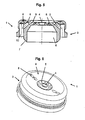
- FIGS. 5 and 6 illustrated embodiment differs from the embodiment according to FIG. 2 in that the end face 9 of the air cap 3 has a slight concave curvature, so that the radially outer edge region protrudes slightly in the axial direction relative to the region surrounding the central bore 4.
- the angle ⁇ with which the shaping air nozzles 8 are arranged inclined relative to the axis of symmetry of the air cap 3, opposite the embodiment according to FIG. 2 for example, from about 53.5 ° (outer mold air nozzles) or about 44.5 ° (inner mold air nozzles) in FIG. 2 to about 60 ° and about 50 ° in the embodiment of the FIGS. 5 and 6 ,
Landscapes
- Nozzles (AREA)
Applications Claiming Priority (1)
| Application Number | Priority Date | Filing Date | Title |
|---|---|---|---|
| DE200720008816 DE202007008816U1 (de) | 2007-06-21 | 2007-06-21 | Zerstäuberkopf für eine Spritzpistole |
Publications (3)
| Publication Number | Publication Date |
|---|---|
| EP2017010A2 true EP2017010A2 (fr) | 2009-01-21 |
| EP2017010A3 EP2017010A3 (fr) | 2009-05-20 |
| EP2017010B1 EP2017010B1 (fr) | 2013-03-27 |
Family
ID=38580470
Family Applications (1)
| Application Number | Title | Priority Date | Filing Date |
|---|---|---|---|
| EP08011130A Active EP2017010B1 (fr) | 2007-06-21 | 2008-06-19 | Tête de distribution pour un pistolet pulvérisateur |
Country Status (3)
| Country | Link |
|---|---|
| EP (1) | EP2017010B1 (fr) |
| DE (1) | DE202007008816U1 (fr) |
| ES (1) | ES2424822T3 (fr) |
Cited By (16)
| Publication number | Priority date | Publication date | Assignee | Title |
|---|---|---|---|---|
| DE102015016474A1 (de) * | 2015-12-21 | 2017-06-22 | Sata Gmbh & Co. Kg | Luftkappe und Düsenanordnung für eine Spritzpistole und Spritzpistole |
| USD798419S1 (en) | 2014-07-31 | 2017-09-26 | Sata Gmbh & Co. Kg | Paint spray gun |
| US9782785B2 (en) | 2010-12-02 | 2017-10-10 | Sata Gmbh & Co. Kg | Spray gun and accessories |
| US9878336B2 (en) | 2006-12-05 | 2018-01-30 | Sata Gmbh & Co. Kg | Fluid reservoir for a paint spray gun |
| US10471449B2 (en) | 2016-08-19 | 2019-11-12 | Sata Gmbh & Co. Kg | Air cap arrangement and spray gun |
| US10702879B2 (en) | 2014-07-31 | 2020-07-07 | Sata Gmbh & Co. Kg | Spray gun manufacturing method, spray gun, spray gun body and cover |
| US10835911B2 (en) | 2016-08-19 | 2020-11-17 | Sata Gmbh & Co. Kg | Trigger for a spray gun and spray gun having same |
| CN113477430A (zh) * | 2021-07-06 | 2021-10-08 | 浙江小伦制药机械有限公司 | 防结须的雾化喷枪 |
| US11141747B2 (en) | 2015-05-22 | 2021-10-12 | Sata Gmbh & Co. Kg | Nozzle arrangement for a spray gun |
| DE102020115837A1 (de) | 2020-06-16 | 2021-12-16 | Bayerische Motoren Werke Aktiengesellschaft | Sprühvorrichtung für eine Sprühpistole, Sprühpistole sowie Verwendung einer Sprühpistole |
| US11801521B2 (en) | 2018-08-01 | 2023-10-31 | Sata Gmbh & Co. Kg | Main body for a spray gun, spray guns, spray gun set, method for producing a main body for a spray gun and method for converting a spray gun |
| US11826771B2 (en) | 2018-08-01 | 2023-11-28 | Sata Gmbh & Co. Kg | Set of nozzles for a spray gun, spray gun system, method for embodying a nozzle module, method for selecting a nozzle module from a set of nozzles for a paint job, selection system and computer program product |
| US11865558B2 (en) | 2018-08-01 | 2024-01-09 | Sata Gmbh & Co. Kg | Nozzle for a spray gun, nozzle set for a spray gun, spray guns and methods for producing a nozzle for a spray gun |
| US12097519B2 (en) | 2020-09-11 | 2024-09-24 | Sata Gmbh & Co. Kg | Sealing element for sealing a transition between a spray gun body and an attachment of a spray gun, attachment, in particular a paint nozzle arrangement for a spray gun and a spray gun, in particular a paint spray gun |
| US12515230B2 (en) | 2018-09-10 | 2026-01-06 | Sata Gmbh & Co. Kg | Paint gun, material application system, and method for operating same |
| US12594566B2 (en) | 2020-03-06 | 2026-04-07 | Sata Gmbh & Co. Kg | Spray gun, in particular a pressurized air atomization paint spray gun, in particular a hand-held pressurized air atomization paint spray gun |
Families Citing this family (1)
| Publication number | Priority date | Publication date | Assignee | Title |
|---|---|---|---|---|
| DE102021004733A1 (de) | 2021-09-21 | 2023-03-23 | Polyplan-GmbH Polyurethan-Maschinen | Düsenvorrichtung |
Citations (4)
| Publication number | Priority date | Publication date | Assignee | Title |
|---|---|---|---|---|
| DE2811436C2 (de) | 1977-03-22 | 1983-07-14 | S K M, S.A., 93240 Stains | Verfahren zur pneumatischen Zerstäubung eines flüssigen Mediums, insbesondere Farbe oder Lack, und Spritzpistole |
| DE3417229C2 (fr) | 1984-05-10 | 1987-07-02 | Fraunhofer-Gesellschaft Zur Foerderung Der Angewandten Forschung E.V., 8000 Muenchen, De | |
| DE9001265U1 (de) | 1990-02-05 | 1990-04-12 | Sata - Farbspritztechnik GmbH & Co, 7140 Ludwigsburg | Düsenkopf für eine Farbspritzpistole |
| DE68924079T2 (de) | 1988-02-01 | 1996-02-01 | Itw Ltd | Sprühpistole. |
Family Cites Families (4)
| Publication number | Priority date | Publication date | Assignee | Title |
|---|---|---|---|---|
| US1873625A (en) * | 1929-09-16 | 1932-08-23 | Ernest Z Munz | Spraying device |
| US5080283A (en) * | 1986-07-14 | 1992-01-14 | Glas-Craft, Inc. | Multi-component application system |
| JPH0724796B2 (ja) * | 1990-05-11 | 1995-03-22 | 岩田塗装機工業株式会社 | 低圧微粒化エアスプレーガン |
| US5452856A (en) * | 1993-12-10 | 1995-09-26 | Davidson Textron, Inc. | Spray wand with spray fan control |
-
2007
- 2007-06-21 DE DE200720008816 patent/DE202007008816U1/de not_active Expired - Lifetime
-
2008
- 2008-06-19 EP EP08011130A patent/EP2017010B1/fr active Active
- 2008-06-19 ES ES08011130T patent/ES2424822T3/es active Active
Patent Citations (4)
| Publication number | Priority date | Publication date | Assignee | Title |
|---|---|---|---|---|
| DE2811436C2 (de) | 1977-03-22 | 1983-07-14 | S K M, S.A., 93240 Stains | Verfahren zur pneumatischen Zerstäubung eines flüssigen Mediums, insbesondere Farbe oder Lack, und Spritzpistole |
| DE3417229C2 (fr) | 1984-05-10 | 1987-07-02 | Fraunhofer-Gesellschaft Zur Foerderung Der Angewandten Forschung E.V., 8000 Muenchen, De | |
| DE68924079T2 (de) | 1988-02-01 | 1996-02-01 | Itw Ltd | Sprühpistole. |
| DE9001265U1 (de) | 1990-02-05 | 1990-04-12 | Sata - Farbspritztechnik GmbH & Co, 7140 Ludwigsburg | Düsenkopf für eine Farbspritzpistole |
Cited By (19)
| Publication number | Priority date | Publication date | Assignee | Title |
|---|---|---|---|---|
| US9878336B2 (en) | 2006-12-05 | 2018-01-30 | Sata Gmbh & Co. Kg | Fluid reservoir for a paint spray gun |
| US9782785B2 (en) | 2010-12-02 | 2017-10-10 | Sata Gmbh & Co. Kg | Spray gun and accessories |
| USD798419S1 (en) | 2014-07-31 | 2017-09-26 | Sata Gmbh & Co. Kg | Paint spray gun |
| USD835235S1 (en) | 2014-07-31 | 2018-12-04 | Sata Gmbh & Co. Kg | Paint spray gun |
| US10702879B2 (en) | 2014-07-31 | 2020-07-07 | Sata Gmbh & Co. Kg | Spray gun manufacturing method, spray gun, spray gun body and cover |
| US11141747B2 (en) | 2015-05-22 | 2021-10-12 | Sata Gmbh & Co. Kg | Nozzle arrangement for a spray gun |
| DE102015016474A1 (de) * | 2015-12-21 | 2017-06-22 | Sata Gmbh & Co. Kg | Luftkappe und Düsenanordnung für eine Spritzpistole und Spritzpistole |
| US10464076B2 (en) | 2015-12-21 | 2019-11-05 | Sata Gmbh & Co. Kg | Air cap and nozzle assembly for a spray gun, and spray gun |
| US10835911B2 (en) | 2016-08-19 | 2020-11-17 | Sata Gmbh & Co. Kg | Trigger for a spray gun and spray gun having same |
| US10471449B2 (en) | 2016-08-19 | 2019-11-12 | Sata Gmbh & Co. Kg | Air cap arrangement and spray gun |
| US11801521B2 (en) | 2018-08-01 | 2023-10-31 | Sata Gmbh & Co. Kg | Main body for a spray gun, spray guns, spray gun set, method for producing a main body for a spray gun and method for converting a spray gun |
| US11826771B2 (en) | 2018-08-01 | 2023-11-28 | Sata Gmbh & Co. Kg | Set of nozzles for a spray gun, spray gun system, method for embodying a nozzle module, method for selecting a nozzle module from a set of nozzles for a paint job, selection system and computer program product |
| US11865558B2 (en) | 2018-08-01 | 2024-01-09 | Sata Gmbh & Co. Kg | Nozzle for a spray gun, nozzle set for a spray gun, spray guns and methods for producing a nozzle for a spray gun |
| US12515230B2 (en) | 2018-09-10 | 2026-01-06 | Sata Gmbh & Co. Kg | Paint gun, material application system, and method for operating same |
| US12594566B2 (en) | 2020-03-06 | 2026-04-07 | Sata Gmbh & Co. Kg | Spray gun, in particular a pressurized air atomization paint spray gun, in particular a hand-held pressurized air atomization paint spray gun |
| DE102020115837A1 (de) | 2020-06-16 | 2021-12-16 | Bayerische Motoren Werke Aktiengesellschaft | Sprühvorrichtung für eine Sprühpistole, Sprühpistole sowie Verwendung einer Sprühpistole |
| US12097519B2 (en) | 2020-09-11 | 2024-09-24 | Sata Gmbh & Co. Kg | Sealing element for sealing a transition between a spray gun body and an attachment of a spray gun, attachment, in particular a paint nozzle arrangement for a spray gun and a spray gun, in particular a paint spray gun |
| CN113477430A (zh) * | 2021-07-06 | 2021-10-08 | 浙江小伦制药机械有限公司 | 防结须的雾化喷枪 |
| CN113477430B (zh) * | 2021-07-06 | 2023-12-12 | 浙江小伦智能制造股份有限公司 | 防结须的雾化喷枪 |
Also Published As
| Publication number | Publication date |
|---|---|
| DE202007008816U1 (de) | 2007-10-11 |
| EP2017010A3 (fr) | 2009-05-20 |
| EP2017010B1 (fr) | 2013-03-27 |
| ES2424822T3 (es) | 2013-10-08 |
Similar Documents
| Publication | Publication Date | Title |
|---|---|---|
| EP2017010B1 (fr) | Tête de distribution pour un pistolet pulvérisateur | |
| EP2566627B1 (fr) | Dispositif de revêtement présentant des jets de produit de revêtement divisés en forme de gouttes | |
| EP0951942B1 (fr) | Procédé et pulvérisateur rotatif pour le revêtement en série de pièces | |
| EP2121197B1 (fr) | Bague de guidage d'air | |
| DE202010012449U1 (de) | Düsenanordnung für eine Spritzpistole, insbesondere für eine Farbspritzpistole | |
| EP0710506B1 (fr) | Buse pour pistolet de pulvérisation de peinture | |
| WO2009149950A1 (fr) | Pulvérisateur universel | |
| DE102018118737A1 (de) | Düse für eine Spritzpistole, Düsensatz für eine Spritzpistole, Spritzpistolen und Verfahren zur Herstellung einer Düse für eine Spritzpistole | |
| EP3626352A1 (fr) | Corps de base pour un pistolet de pulvérisation, pistolet de pulvérisation, ensemble pistolet de pulvérisation et procédé de rééquipement d'un pistolet de pulvérisation | |
| EP2461909A1 (fr) | Buse fendue | |
| DE102015006484A1 (de) | Düsenanordnung für eine Spritzpistole, insbesondere Farbspritzpistole und Spritzpistole, insbesondere Farbspritzpistole | |
| DE202009019107U1 (de) | Rotationsspritzvorrichtung für ein Beschichtungsprodukt | |
| EP3184177A1 (fr) | Volet d'aération et système de buse pour un pistolet pulvérisateur et pistolet pulvérisateur | |
| EP3034175B1 (fr) | Tete de buse et pulverisateur rotatif en etant dote | |
| EP2143500B1 (fr) | Procédé et pulvérisateur pour le revêtement de pièces en séries | |
| EP3204167A1 (fr) | Buse bimatière | |
| EP1280610B1 (fr) | Buse melangeuse externe | |
| DE202010015304U1 (de) | Düse | |
| EP0192099B1 (fr) | Procédé de revêtement des objets et appareil pour l'exécution de ce procédé | |
| DE202015003664U1 (de) | Düsenanordnung für eine Spritzpistole, insbesondere Farbspritzpistole und Spritzpistole, insbesondere Farbspritzpistole | |
| DE19643621B4 (de) | Luftkappe für pneumatische Lackspritzvorrichtungen und pneumatisches Aufbringverfahren | |
| EP0695582A1 (fr) | Procédé et dispositif de revêtement électrostatique et/ou pneumatique d'un substrat conducteur par un produit de revêtement liquide | |
| DE102024107326A1 (de) | Farbdüse für eine Lackierpistole | |
| DE102017116669A1 (de) | Glockenteller und Rotationszerstäuber | |
| DE102017116715A1 (de) | Düsenkopf für einen Rotationszerstäuber zum Aufbringen eines Beschichtungsmaterials auf einen Gegenstand |
Legal Events
| Date | Code | Title | Description |
|---|---|---|---|
| PUAI | Public reference made under article 153(3) epc to a published international application that has entered the european phase |
Free format text: ORIGINAL CODE: 0009012 |
|
| PUAI | Public reference made under article 153(3) epc to a published international application that has entered the european phase |
Free format text: ORIGINAL CODE: 0009012 |
|
| AK | Designated contracting states |
Kind code of ref document: A2 Designated state(s): AT BE BG CH CY CZ DE DK EE ES FI FR GB GR HR HU IE IS IT LI LT LU LV MC MT NL NO PL PT RO SE SI SK TR |
|
| AX | Request for extension of the european patent |
Extension state: AL BA MK RS |
|
| PUAL | Search report despatched |
Free format text: ORIGINAL CODE: 0009013 |
|
| AK | Designated contracting states |
Kind code of ref document: A3 Designated state(s): AT BE BG CH CY CZ DE DK EE ES FI FR GB GR HR HU IE IS IT LI LT LU LV MC MT NL NO PL PT RO SE SI SK TR |
|
| AX | Request for extension of the european patent |
Extension state: AL BA MK RS |
|
| RAP1 | Party data changed (applicant data changed or rights of an application transferred) |
Owner name: INDUSTRA INDUSTRIEANLAGEN - MASCHINEN UND TEILE GM |
|
| 17P | Request for examination filed |
Effective date: 20090813 |
|
| 17Q | First examination report despatched |
Effective date: 20090910 |
|
| AKX | Designation fees paid |
Designated state(s): AT BE BG CH CY CZ DE DK EE ES FI FR GB GR HR HU IE IS IT LI LT LU LV MC MT NL NO PL PT RO SE SI SK TR |
|
| GRAP | Despatch of communication of intention to grant a patent |
Free format text: ORIGINAL CODE: EPIDOSNIGR1 |
|
| GRAS | Grant fee paid |
Free format text: ORIGINAL CODE: EPIDOSNIGR3 |
|
| GRAA | (expected) grant |
Free format text: ORIGINAL CODE: 0009210 |
|
| AK | Designated contracting states |
Kind code of ref document: B1 Designated state(s): AT BE BG CH CY CZ DE DK EE ES FI FR GB GR HR HU IE IS IT LI LT LU LV MC MT NL NO PL PT RO SE SI SK TR |
|
| REG | Reference to a national code |
Ref country code: GB Ref legal event code: FG4D Free format text: NOT ENGLISH |
|
| REG | Reference to a national code |
Ref country code: CH Ref legal event code: EP |
|
| REG | Reference to a national code |
Ref country code: AT Ref legal event code: REF Ref document number: 603023 Country of ref document: AT Kind code of ref document: T Effective date: 20130415 |
|
| REG | Reference to a national code |
Ref country code: IE Ref legal event code: FG4D Free format text: LANGUAGE OF EP DOCUMENT: GERMAN |
|
| REG | Reference to a national code |
Ref country code: DE Ref legal event code: R096 Ref document number: 502008009566 Country of ref document: DE Effective date: 20130523 |
|
| PG25 | Lapsed in a contracting state [announced via postgrant information from national office to epo] |
Ref country code: LT Free format text: LAPSE BECAUSE OF FAILURE TO SUBMIT A TRANSLATION OF THE DESCRIPTION OR TO PAY THE FEE WITHIN THE PRESCRIBED TIME-LIMIT Effective date: 20130327 Ref country code: NO Free format text: LAPSE BECAUSE OF FAILURE TO SUBMIT A TRANSLATION OF THE DESCRIPTION OR TO PAY THE FEE WITHIN THE PRESCRIBED TIME-LIMIT Effective date: 20130627 Ref country code: SE Free format text: LAPSE BECAUSE OF FAILURE TO SUBMIT A TRANSLATION OF THE DESCRIPTION OR TO PAY THE FEE WITHIN THE PRESCRIBED TIME-LIMIT Effective date: 20130327 Ref country code: BG Free format text: LAPSE BECAUSE OF FAILURE TO SUBMIT A TRANSLATION OF THE DESCRIPTION OR TO PAY THE FEE WITHIN THE PRESCRIBED TIME-LIMIT Effective date: 20130627 |
|
| REG | Reference to a national code |
Ref country code: LT Ref legal event code: MG4D |
|
| PG25 | Lapsed in a contracting state [announced via postgrant information from national office to epo] |
Ref country code: LV Free format text: LAPSE BECAUSE OF FAILURE TO SUBMIT A TRANSLATION OF THE DESCRIPTION OR TO PAY THE FEE WITHIN THE PRESCRIBED TIME-LIMIT Effective date: 20130327 Ref country code: FI Free format text: LAPSE BECAUSE OF FAILURE TO SUBMIT A TRANSLATION OF THE DESCRIPTION OR TO PAY THE FEE WITHIN THE PRESCRIBED TIME-LIMIT Effective date: 20130327 Ref country code: GR Free format text: LAPSE BECAUSE OF FAILURE TO SUBMIT A TRANSLATION OF THE DESCRIPTION OR TO PAY THE FEE WITHIN THE PRESCRIBED TIME-LIMIT Effective date: 20130628 Ref country code: SI Free format text: LAPSE BECAUSE OF FAILURE TO SUBMIT A TRANSLATION OF THE DESCRIPTION OR TO PAY THE FEE WITHIN THE PRESCRIBED TIME-LIMIT Effective date: 20130327 |
|
| REG | Reference to a national code |
Ref country code: NL Ref legal event code: VDEP Effective date: 20130327 |
|
| PG25 | Lapsed in a contracting state [announced via postgrant information from national office to epo] |
Ref country code: HR Free format text: LAPSE BECAUSE OF FAILURE TO SUBMIT A TRANSLATION OF THE DESCRIPTION OR TO PAY THE FEE WITHIN THE PRESCRIBED TIME-LIMIT Effective date: 20130327 |
|
| REG | Reference to a national code |
Ref country code: ES Ref legal event code: FG2A Ref document number: 2424822 Country of ref document: ES Kind code of ref document: T3 Effective date: 20131008 |
|
| PG25 | Lapsed in a contracting state [announced via postgrant information from national office to epo] |
Ref country code: PT Free format text: LAPSE BECAUSE OF FAILURE TO SUBMIT A TRANSLATION OF THE DESCRIPTION OR TO PAY THE FEE WITHIN THE PRESCRIBED TIME-LIMIT Effective date: 20130729 Ref country code: SK Free format text: LAPSE BECAUSE OF FAILURE TO SUBMIT A TRANSLATION OF THE DESCRIPTION OR TO PAY THE FEE WITHIN THE PRESCRIBED TIME-LIMIT Effective date: 20130327 Ref country code: RO Free format text: LAPSE BECAUSE OF FAILURE TO SUBMIT A TRANSLATION OF THE DESCRIPTION OR TO PAY THE FEE WITHIN THE PRESCRIBED TIME-LIMIT Effective date: 20130327 Ref country code: CZ Free format text: LAPSE BECAUSE OF FAILURE TO SUBMIT A TRANSLATION OF THE DESCRIPTION OR TO PAY THE FEE WITHIN THE PRESCRIBED TIME-LIMIT Effective date: 20130327 Ref country code: NL Free format text: LAPSE BECAUSE OF FAILURE TO SUBMIT A TRANSLATION OF THE DESCRIPTION OR TO PAY THE FEE WITHIN THE PRESCRIBED TIME-LIMIT Effective date: 20130327 Ref country code: EE Free format text: LAPSE BECAUSE OF FAILURE TO SUBMIT A TRANSLATION OF THE DESCRIPTION OR TO PAY THE FEE WITHIN THE PRESCRIBED TIME-LIMIT Effective date: 20130327 Ref country code: IS Free format text: LAPSE BECAUSE OF FAILURE TO SUBMIT A TRANSLATION OF THE DESCRIPTION OR TO PAY THE FEE WITHIN THE PRESCRIBED TIME-LIMIT Effective date: 20130727 |
|
| PG25 | Lapsed in a contracting state [announced via postgrant information from national office to epo] |
Ref country code: CY Free format text: LAPSE BECAUSE OF FAILURE TO SUBMIT A TRANSLATION OF THE DESCRIPTION OR TO PAY THE FEE WITHIN THE PRESCRIBED TIME-LIMIT Effective date: 20130327 Ref country code: PL Free format text: LAPSE BECAUSE OF FAILURE TO SUBMIT A TRANSLATION OF THE DESCRIPTION OR TO PAY THE FEE WITHIN THE PRESCRIBED TIME-LIMIT Effective date: 20130327 |
|
| BERE | Be: lapsed |
Owner name: INDUSTRA INDUSTRIEANLAGEN - MASCHINEN UND TEILE G Effective date: 20130630 |
|
| PG25 | Lapsed in a contracting state [announced via postgrant information from national office to epo] |
Ref country code: DK Free format text: LAPSE BECAUSE OF FAILURE TO SUBMIT A TRANSLATION OF THE DESCRIPTION OR TO PAY THE FEE WITHIN THE PRESCRIBED TIME-LIMIT Effective date: 20130327 Ref country code: MC Free format text: LAPSE BECAUSE OF FAILURE TO SUBMIT A TRANSLATION OF THE DESCRIPTION OR TO PAY THE FEE WITHIN THE PRESCRIBED TIME-LIMIT Effective date: 20130327 |
|
| PLBE | No opposition filed within time limit |
Free format text: ORIGINAL CODE: 0009261 |
|
| REG | Reference to a national code |
Ref country code: CH Ref legal event code: PL |
|
| STAA | Information on the status of an ep patent application or granted ep patent |
Free format text: STATUS: NO OPPOSITION FILED WITHIN TIME LIMIT |
|
| 26N | No opposition filed |
Effective date: 20140103 |
|
| REG | Reference to a national code |
Ref country code: IE Ref legal event code: MM4A |
|
| PG25 | Lapsed in a contracting state [announced via postgrant information from national office to epo] |
Ref country code: BE Free format text: LAPSE BECAUSE OF NON-PAYMENT OF DUE FEES Effective date: 20130630 |
|
| REG | Reference to a national code |
Ref country code: DE Ref legal event code: R097 Ref document number: 502008009566 Country of ref document: DE Effective date: 20140103 |
|
| PG25 | Lapsed in a contracting state [announced via postgrant information from national office to epo] |
Ref country code: LI Free format text: LAPSE BECAUSE OF NON-PAYMENT OF DUE FEES Effective date: 20130630 Ref country code: CH Free format text: LAPSE BECAUSE OF NON-PAYMENT OF DUE FEES Effective date: 20130630 Ref country code: IE Free format text: LAPSE BECAUSE OF NON-PAYMENT OF DUE FEES Effective date: 20130619 |
|
| REG | Reference to a national code |
Ref country code: AT Ref legal event code: MM01 Ref document number: 603023 Country of ref document: AT Kind code of ref document: T Effective date: 20130619 |
|
| PG25 | Lapsed in a contracting state [announced via postgrant information from national office to epo] |
Ref country code: AT Free format text: LAPSE BECAUSE OF NON-PAYMENT OF DUE FEES Effective date: 20130619 |
|
| PG25 | Lapsed in a contracting state [announced via postgrant information from national office to epo] |
Ref country code: MT Free format text: LAPSE BECAUSE OF FAILURE TO SUBMIT A TRANSLATION OF THE DESCRIPTION OR TO PAY THE FEE WITHIN THE PRESCRIBED TIME-LIMIT Effective date: 20130327 |
|
| PG25 | Lapsed in a contracting state [announced via postgrant information from national office to epo] |
Ref country code: TR Free format text: LAPSE BECAUSE OF FAILURE TO SUBMIT A TRANSLATION OF THE DESCRIPTION OR TO PAY THE FEE WITHIN THE PRESCRIBED TIME-LIMIT Effective date: 20130327 |
|
| PG25 | Lapsed in a contracting state [announced via postgrant information from national office to epo] |
Ref country code: HU Free format text: LAPSE BECAUSE OF FAILURE TO SUBMIT A TRANSLATION OF THE DESCRIPTION OR TO PAY THE FEE WITHIN THE PRESCRIBED TIME-LIMIT; INVALID AB INITIO Effective date: 20080619 Ref country code: LU Free format text: LAPSE BECAUSE OF NON-PAYMENT OF DUE FEES Effective date: 20130619 |
|
| REG | Reference to a national code |
Ref country code: FR Ref legal event code: PLFP Year of fee payment: 9 |
|
| REG | Reference to a national code |
Ref country code: FR Ref legal event code: PLFP Year of fee payment: 10 |
|
| REG | Reference to a national code |
Ref country code: FR Ref legal event code: PLFP Year of fee payment: 11 |
|
| PGFP | Annual fee paid to national office [announced via postgrant information from national office to epo] |
Ref country code: DE Payment date: 20250626 Year of fee payment: 18 |
|
| PGFP | Annual fee paid to national office [announced via postgrant information from national office to epo] |
Ref country code: FR Payment date: 20250626 Year of fee payment: 18 |
|
| PGFP | Annual fee paid to national office [announced via postgrant information from national office to epo] |
Ref country code: ES Payment date: 20250718 Year of fee payment: 18 |
|
| PGFP | Annual fee paid to national office [announced via postgrant information from national office to epo] |
Ref country code: IT Payment date: 20250626 Year of fee payment: 18 |
|
| PGFP | Annual fee paid to national office [announced via postgrant information from national office to epo] |
Ref country code: GB Payment date: 20250724 Year of fee payment: 18 |