EP2017012A2 - Curtain coating machine - Google Patents
Curtain coating machine Download PDFInfo
- Publication number
- EP2017012A2 EP2017012A2 EP08160076A EP08160076A EP2017012A2 EP 2017012 A2 EP2017012 A2 EP 2017012A2 EP 08160076 A EP08160076 A EP 08160076A EP 08160076 A EP08160076 A EP 08160076A EP 2017012 A2 EP2017012 A2 EP 2017012A2
- Authority
- EP
- European Patent Office
- Prior art keywords
- curtain
- layer
- guide plate
- guide
- edge
- Prior art date
- Legal status (The legal status is an assumption and is not a legal conclusion. Google has not performed a legal analysis and makes no representation as to the accuracy of the status listed.)
- Ceased
Links
- 238000007766 curtain coating Methods 0.000 title abstract description 3
- 239000010410 layer Substances 0.000 claims description 90
- 239000011248 coating agent Substances 0.000 claims description 27
- 238000000576 coating method Methods 0.000 claims description 27
- 239000011241 protective layer Substances 0.000 claims description 21
- 238000005192 partition Methods 0.000 claims description 13
- 238000004519 manufacturing process Methods 0.000 claims description 6
- 235000011837 pasties Nutrition 0.000 abstract 2
- 238000011144 upstream manufacturing Methods 0.000 description 5
- 230000000694 effects Effects 0.000 description 4
- 239000004744 fabric Substances 0.000 description 4
- 238000011109 contamination Methods 0.000 description 2
- 238000012423 maintenance Methods 0.000 description 2
- 239000003973 paint Substances 0.000 description 2
- 230000008719 thickening Effects 0.000 description 2
- 206010044625 Trichorrhexis Diseases 0.000 description 1
- 238000007796 conventional method Methods 0.000 description 1
- 230000001419 dependent effect Effects 0.000 description 1
- 238000001035 drying Methods 0.000 description 1
- 238000003384 imaging method Methods 0.000 description 1
- 238000003780 insertion Methods 0.000 description 1
- 230000037431 insertion Effects 0.000 description 1
- 239000007788 liquid Substances 0.000 description 1
- 238000000034 method Methods 0.000 description 1
- 238000010422 painting Methods 0.000 description 1
- 238000003825 pressing Methods 0.000 description 1
- 230000001681 protective effect Effects 0.000 description 1
- 238000000638 solvent extraction Methods 0.000 description 1
Images

Classifications
-
- B—PERFORMING OPERATIONS; TRANSPORTING
- B05—SPRAYING OR ATOMISING IN GENERAL; APPLYING FLUENT MATERIALS TO SURFACES, IN GENERAL
- B05C—APPARATUS FOR APPLYING FLUENT MATERIALS TO SURFACES, IN GENERAL
- B05C5/00—Apparatus in which liquid or other fluent material is projected, poured or allowed to flow on to the surface of the work
- B05C5/007—Slide-hopper coaters, i.e. apparatus in which the liquid or other fluent material flows freely on an inclined surface before contacting the work
- B05C5/008—Slide-hopper curtain coaters
Definitions
- the present invention relates to a curtain coater for coating a running paper, board or other fibrous web, comprising a first curtain head for dispensing a first coating medium for a first curtain layer and a second curtain head for dispensing a second coating medium for a second curtain layer, the first curtain head upstream of the second curtain head and both curtain heads emit their curtain layers downwardly, and having an inclined guide plate which is disposed below the curtain heads and which receives the curtain layers discharged from the curtain heads and flow down along its slope, the curtain layers of a curtain guide from falling on the surface of the web to be coated (w) in the form of a curtain.
- Printing paper such as for catalogs and coated paper, which is used, among other things, for pressure-sensitive paper or thermal paper, is prepared by applying a coating to the surface of the web (base paper) with a coater and then drying it.
- Machines that perform the coating of the strokes in this way are called coaters.
- doctor blade coaters doctor blade coaters such as a round bar, or a blade or air knife machines to which the post-metering method is applied. In this first the line is applied in a more than necessary amount on the web, and then stripped with the said doctor element (metered) or blown off with an air knife.
- the painting Redispensing the problems that penetrates deep into the web by the pressing force of the doctor blade or by the liquid pressure when applying the stroke on the web of the stroke, or that the maintenance costs are high due to the wear of the doctor element.
- curtain coating machines have been used in general, in which the curtain layer is discharged from the curtain heads (chambers with nozzles) and thus the web is coated.
- Curtain coaters have long been used for photographic paper, but because of the instability of the curtain layer due to the trapping of air, bubbles trapped in the line at high speeds, or lack of mechanical accuracy, the stroke was not stable, so it was not suitable for the papermaking were used.
- the curtain coater in contrast to the conventional Nachdosiermethoden no wearing parts such as doctor blade or rods.
- the maintenance is simple, the amount of coating can be adjusted easily and with high accuracy, the operability is good and also the effect of the surface improvement for a covering coat to be applied is high. Etc.
- the web be coated with two or more layers.
- two curtain heads are placed one behind the other at the top of the moving web and the two-layer stroke is formed by letting the applied curtain down onto the top of the web.
- this curtain-type coating machine when used for paper webs, the webs are transported at a high speed of 300 to 2000 m / min, so that a large difference in speed results because the lowering speed of the curtain is about 180 m / min. In such a case, the curtain forming the lower layer arrives wet on the dry surface of the web. The friction factor between the two is relatively large. The web surface is pulled uniformly and normally, as a first layer (lower layer), a uniform coating without unevenness is formed.
- the friction factor therebetween will be low and slippage will occur.
- the surface of the coating of the first layer can not be pulled well, causing bumps. It can also happen that the coating of the second layer (upper layer) does not form normally.
- FIG. 4 shows a part of the side view of the coating device. Like in the FIG. 4 is shown, a curtain coater for two layers is provided. It has two curtain heads 1a, 1b, which output the lines ta, tb, which flow in the slits da, db, respectively directed downwards. In addition, an inclined guide plate 2 is present, which the strokes ta, tb - issued by the two
- curtain heads 1a, 1b- in each case downwardly in turn on the slope 2a slide, these lines or layers are stacked with the movement on the slope 2a of the guide plate 2 in turn and from the downward tear-off edge of the curtain guide 2b as line curtains ca, cb moved to the surface of the web w.
- a line with two layers, sa (lower layer), sb (upper layer) are formed on the surface of the transported web w.
- the arrow indicates the direction of movement of the web w.
- thermal paper is to be produced with the curtain coater described here, where two application layers are necessary, namely a heat-sensitive layer and then a protective layer
- this paper thus treated is smoothed after being coated and dried by a cloth press roller.
- the coating width of the heat-sensitive layer is narrower than the coating width of the protective layer, the heat-sensitive layer comes into direct contact with the cloth press roller, thus contaminating the roll and thus posing an obstacle to operation. Therefore, it is necessary that the width of the Protective layer is wider than the line width of the heat-sensitive layer, and that the heat-sensitive layer is completely covered by the protective layer.
- the width of the stroke ta applied by the curtain head 1a for the heat-sensitive layer stroke must be changed in accordance with the width of the web w.
- the width of the stroke ta which is output from the curtain head 1a, in accordance with the output width is a slot on both sides of the slot there, from the the dash ta flows inside the curtain head 1a, pushed in, or there is a sliding lid inserted at both ends of the slot there.
- the machine has to be stopped in order to change the slot, but the stop results in a loss of productivity, and it also means that the slot to be replaced is firmly seated and can not be removed. If a sliding lid is used, the machine does not have to be stopped, but after long use it settles down and can not be moved, so that the line emerges from the gap between the slot and lid, and it becomes technically difficult. To insert the lid, since the width of the gap is narrow at 0.3 to 0.5 mm.
- the invention is therefore based on the object of specifying a curtain coater in which the disadvantages of the prior art do not occur.
- the object is achieved with the characterizing features of claim 1 such that a device for adjusting the Application width is provided for the first curtain layer arranged to be below the first curtain head for the first layer and associated with the lateral upper portion of the guide plate such that a central portion of the first curtain layer dispensed from the curtain head of FIG lateral parts of the same layer is separable, whereby the middle part slides down on the surface of the guide plate and the lateral parts flow in the opposite direction as the flow of the middle part.
- the width of this line dispensed from the curtain head for that layer need not change but is output across the entire width and into a middle one after dispensing Split part and part at both ends. The middle part then gets on the track, whereas the two side parts are collected.
- the technical difficulties in the case of changing widths of the bar, which is released from the curtain head for the first layer are solved.
- retraction (narrowing of the width with simultaneous increase in thickness by this proportion), which occurs at the edges of the line due to surface tension of the application medium, is avoided.
- the effect and operation of the present invention are as follows.
- the stroke of the first applied application medium which is output from the upstream curtain head downwards over the entire width, by a pair of device for adjusting the stroke width, which are provided directed downward, in a middle part and in a part at both Split ends. That is, the part meets on both sides of this first layer (on the web the lower layer) on the partition plate, which has a gradient opposite to the guide plate, flows on the partition plate in the opposite direction downwards and is collected by the ink pan.
- the middle part which exits as it flows downward impinges on the guide plate near the upper edge and flows along the slope thereof and moves from the lower edge of the downwardly directed curtain guide to the surface of the web as a curtain ,
- the impact position of the slash of the second applied sliver layer discharged from the second curtain head may occur.
- the guide plate only slightly (eg, 1 to 2 mm) of the lower edge of the edge guide is downstream of the guide plate so that the flow of the first layer stroke on the guide plate slope is restricted by the guide plate and the second stroke flow. This is done at the time it decides whether or not it will pull in, so there is no catchment in the flow of the first layer.
- both ends of the flow of the stroke of the second Although there may be layers of edge thickening on the surface of the web, they can be cut off by a knife and no problems are caused.
- the point of impact of the second layer emitted by the second curtain head may also be somewhat upstream (e.g., about 1 to 2 mm) from the lower edge of the edge guide on the guide plate on the guide plate. In this case, under no circumstances does the problem of drawing in the flow of the first stroke occur.
- the stroke for the first layer is outputted over the entire width, divided into a middle part and a part at both ends after dispensing, the middle part is applied to the web, and the part at both ends is collected.
- the present invention is particularly suitable for the production of Thermal paper.
- a heat-sensitive layer is applied by means of the first curtain head. This is the surface of the web completely covered by the second applied layer, the protective layer, on the whole width. This is true even if the width of the protective line output from the curtain head for the protective layer is larger than the largest width between the areas on the inside of the bar width adjusting device.
- 1a denotes the curtain head for a first coating medium ta for a first layer ca, i. for a heat-sensitive layer sb.
- the curtain head 1a is arranged upstream of a second curtain head 1b for a second application medium tb or for a second layer cb or for a protective layer sb.
- Denoted by 2 is a guide plate which receives the media originating from these curtain heads 1a, 1b on their bevel 2a and allows them to flow down along the bevels 2a. From a downwardly directed lower edge (tear-off edge) of the curtain guide 2b, the media ta, tb reach the surface of the web w as a falling line curtain c.
- the upper edge of the guide plate 2 has a bent portion 2c with a gradient which is reversed to the slope 2a along which the bar to be applied flows.
- the Device 9 is disposed below the curtain head 1 a for the heat-sensitive layer and is arranged symmetrically to the surfaces (vertical surfaces including the center line c1 of the coating machine) at the two ends of the upstream guide plate 2, the position of which is adjustable in width and the surface of a to the gradient of the guide plate 2 has opposite gradient on which the middle part tac of the stroke ta of the heat-sensitive layer discharged from the curtain head 1a for the heat-sensitive layer on the guide plate 2 flows, and on which the part of both ends tae of first coating medium ta of the heat-sensitive layer, which is discharged from the curtain head 1a for the heat-sensitive layer on the guide plate 2 and flows on the surface thereof in the direction opposite to the flow on the guide plate 2.
- the bar width setting device 9 has a pair of edge guides 3 extending downward from the upper edge of the guide plate 2, parallel to the inner surface, and also parallel to the center line c1 of the coating machine.
- the edge guides 3 bear against the surface of the guide plate 2 and are pointed at their lower edge.
- a parallel pair of auxiliary guides 4 is provided, which are fixedly mounted in the region of the upper edges of the edge guides 3 of the relevant plate and which are seen from the outside wedge-shaped. Their surface has a gradient which is opposite to the gradient of the guide plate 2.
- a parallel pair of partition plates 5 are provided, which are fixedly mounted on the surface of the respective auxiliary guides 4 and whose surface has a gradient which is the same as the gradient of Surface of the auxiliary guides 4. In the area of the lower edge 3a of the edge guides 3 on the guide plate whose thickness is reduced, as in Figure. 1 and 2 is shown.
- the partition plate 5 is as shown in the figures bent at the edge downwards.
- the surfaces of the inner sides of the edge guides 3 on the guide plate, the surfaces of the inner sides of the auxiliary guides 4 and the surfaces of the inner sides of the partition plate 5 form, as in FIG. 1 and 2 represented, a uniform vertical guide surface 9a.
- the stroke tae flowing on the partitioning plate 5 of the bar width adjusting device 9 is collected by the ink fountain 7.
- the positioning device 6 denotes a device for positioning. With this device 6, the adjustment of the position of the device 9 for adjusting the stroke width is made in the transverse direction.
- the positioning device 6 consists of bolts 6a which are rotatably mounted on the side surfaces of the outsides of the edge guides 3 on the plate and consists of nut members 6b which are positively connected to the respective bolts 6a and at the same time fixedly mounted on the end surfaces of the guide plate 2 are.
- the width of the coating medium tb discharged from the curtain layer head 1b for the protective layer is larger than the largest width between the surfaces 9a of the inner surfaces of the bar width adjusting device 9.
- Designated at 8 is a pair of edge guides parallel to each other, which are provided to guide the part of the curtain c which extends from the curtain guide 2b to the web w.
- another guide surface is present, the one Constriction of the curtain c prevented.
- the line ta of the heat-sensitive layer which is discharged from the curtain-side head 1a for the heat-sensitive layer downwards over the entire width, is divided into a middle part tac and a unit by the bar width adjusting device 9 arranged below Part tae divided for both sides. That the part tae for both sides of the discharged medium ta of the heat-sensitive layer strikes the partition plate 5 which has a gradient opposite to the guide plate 2, flows downward on the partition plate 5 and is caught by the ink pan 7.
- the middle part tac of the discharged stroke ta is directed downward as it is, hits in the region of the upper edge of the guide plate 2, flows down along its slope 2a, and moves from the downwardly facing curtain guide 2b to the line curtain c Surface of the railway w.
- the area of the inside of the edge guide 3 on the plate of the device for setting the stroke width the area of the inside of the
- Auxiliary guide 4 and the surfaces of the inside of the partition plate 5 a uniform vertical guide surface 9a, so that the side surfaces of the central part tac is guided by this vertical guide surface 9a and so arrives on the slope 2a of the guide plate 2.
- the flow of the stroke tac of the heat-sensitive layer is passed through the surface of the inside of the edge guide 3 on the plate. Consequently, up to the lower edge 3a of the edge guide 3 on the plate no retraction caused.
- the heat-sensitive layer sa on the surface of the web w is completely covered completely by the protective layer sb (even if the width of the stroke tb output from the protective-layer curtain head 1b is larger than the largest width between the surfaces 9a on the inside of the device for adjusting the line width 9), there is no direct contact of the heat-sensitive layer sa with a cloth press roller present in the manufacture of the thermal paper web and thus the problem of contamination of the roller surface does not occur.
- the present invention is not limited to the configuration in the above-described embodiment, but it may be changed. as long as the main contents of the invention are not violated.
- a combination of bolts 6a and nut member 6b for the positioning device 6 has been described, but for example, a combination with a rack or a linear motor may also be used.
Landscapes
- Coating Apparatus (AREA)
- Paper (AREA)
- Heat Sensitive Colour Forming Recording (AREA)
Abstract
Description
Die vorliegende Erfindung betrifft eine Vorhangstreichmaschine zur Beschichtung einer laufenden Papier-, Karton oder anderen Faserstoffbahn, aufweisend einen ersten Vorhangkopf zur Abgabe eines ersten Auftragsmediums für eine erste Vorhangschicht und aufweisend einen zweiten Vorhangkopf zur Abgabe eines zweiten Auftragsmediums für eine zweite Vorhangschicht, wobei der erste Vorhangkopf dem zweiten Vorhangkopf vorgelagert ist und beide Vorhangköpfe ihre Vorhangschichten nach unten gerichtet abgeben, sowie aufweisend eine schräg gestellte Führungsplatte, welche unterhalb der Vorhangköpfe angeordnet ist und die die von den Vorhangköpfen abgegebenen Vorhangschichten aufnimmt und entlang ihrer Schräge herabfließen lässt, wobei die Vorhangschichten von einer Vorhangführung aus auf die Oberfläche der zu beschichtenden Bahn (w)in Form eines Vorhangs fallen.The present invention relates to a curtain coater for coating a running paper, board or other fibrous web, comprising a first curtain head for dispensing a first coating medium for a first curtain layer and a second curtain head for dispensing a second coating medium for a second curtain layer, the first curtain head upstream of the second curtain head and both curtain heads emit their curtain layers downwardly, and having an inclined guide plate which is disposed below the curtain heads and which receives the curtain layers discharged from the curtain heads and flow down along its slope, the curtain layers of a curtain guide from falling on the surface of the web to be coated (w) in the form of a curtain.
Druckpapier wie für Kataloge und beschichtetes Papier, welches u.a. für druckempfindliches Papier oder Thermopapier verwendet wird, wird hergestellt, indem mit einer Streichmaschine auf die Oberfläche der Bahn (Grundpapier), ein Strich aufgetragen, und dieser dann getrocknet wird. Maschinen, die die Beschichtung der Striche auf diese Weise ausführen, werden Streichmaschinen genannt. Bei diesen herkömmlichen Streichmaschinen gab es hauptsächlich Rakelstreichmaschinen, Streichmaschinen mit einem Rakelelement, wie einem runden Stab oder einer Klinge oder Luftmessermaschinen, bei denen die Nachdosiermethode angewendet wird. Bei dieser wird zuerst der Strich in einer mehr als notwendigen Menge auf die Bahn aufgetragen, und dann mit dem besagten Rakelelement abgestriffen (dosiert) oder mit einem Luftmesser abgeblasen. Allerdings gibt es bei dem Streichen durch Nachdosieren die Probleme, dass durch die Andrückkraft des Rakels oder durch den Flüssigkeitsdruck beim Auftragen des Strichs auf die Bahn der Strich tief in die Bahn eindringt, oder dass die Wartungskosten hoch sind bedingt durch den Verschleiß des Rakelelements.Printing paper, such as for catalogs and coated paper, which is used, among other things, for pressure-sensitive paper or thermal paper, is prepared by applying a coating to the surface of the web (base paper) with a coater and then drying it. Machines that perform the coating of the strokes in this way are called coaters. In these conventional coating machines, there have been mainly doctor blade coaters, doctor blade coaters such as a round bar, or a blade or air knife machines to which the post-metering method is applied. In this first the line is applied in a more than necessary amount on the web, and then stripped with the said doctor element (metered) or blown off with an air knife. However, there are problems with the painting Redispensing the problems that penetrates deep into the web by the pressing force of the doctor blade or by the liquid pressure when applying the stroke on the web of the stroke, or that the maintenance costs are high due to the wear of the doctor element.
Hierauf wurden in den letzten Jahren immer mehr Vorhangstreichmaschinen allgemein eingesetzt, bei denen aus den Vorhangköpfen (Kammern mit Düsen) die Vorhangschicht abgegeben wird und damit die Bahn beschichtet wird. Vorhangstreichmaschinen werden schon seit langem für Fotopapier verwendet, aber wegen der Instabilität der Vorhangschicht durch das Einschließen von Luft, von Blasen, die in den Strich eingeschlossen sind bei hohen Geschwindigkeiten oder durch die mangelnde mechanische Genauigkeit war der Strich nicht stabil, so dass sie nicht für die Papierherstellung eingesetzt wurden.Thereupon, in recent years, more and more curtain coating machines have been used in general, in which the curtain layer is discharged from the curtain heads (chambers with nozzles) and thus the web is coated. Curtain coaters have long been used for photographic paper, but because of the instability of the curtain layer due to the trapping of air, bubbles trapped in the line at high speeds, or lack of mechanical accuracy, the stroke was not stable, so it was not suitable for the papermaking were used.
Die Vorhangstreichmaschinen haben aber im Gegensatz zu den herkömmlichen Nachdosiermethoden keine Verschleißteile wie Rakel oder Stäbe. Dadurch ist die Wartung einfach, die Strichmenge einfach und mit hoher Genauigkeit einstellbar, die Bedienbarkeit ist gut und auch die Wirkung der Oberflächenverbesserung für eine aufzubringende Deckschicht (contour coat) ist hoch. etc.The curtain coater, however, in contrast to the conventional Nachdosiermethoden no wearing parts such as doctor blade or rods. As a result, the maintenance is simple, the amount of coating can be adjusted easily and with high accuracy, the operability is good and also the effect of the surface improvement for a covering coat to be applied is high. Etc.
Oftmals wird gefordert, dass die Bahn mit zwei oder mehr Schichten zu bestreichen ist. In solchen Fällen werden zwei Vorhangköpfe hintereinander an der Oberseite der sich bewegenden Bahn angeordnet und der Strich aus zwei Schichten ausgebildet, indem der aufgebrachte Vorhang auf die Oberseite der Bahn herab gelassen wird.Often, it is required that the web be coated with two or more layers. In such cases, two curtain heads are placed one behind the other at the top of the moving web and the two-layer stroke is formed by letting the applied curtain down onto the top of the web.
Ist bei einer solchen Streichmaschine mit Vorhangmethode die Geschwindigkeit, mit der sich die Bahn fortbewegt, gering (z.B. 120m/min) wie bei einem Film von Photos, so wird eine Beschichtung mit zwei Schichten normal ausgebildet, weil kein großer Unterschied bei der Transportgeschwindigkeit zwischen Herablassen des Strichvorhangs und der Transportgeschwindigkeit des Films besteht.With such a curtain-type coating machine, if the speed at which the web travels is low (eg, 120 m / min), as in a film of photos, a coating of two will be formed Layers normally formed, because there is no great difference in the transport speed between lowering the line curtain and the transport speed of the film.
Wird jedoch diese Streichmaschine mit Vorhangmethode für Bahnen aus Papier eingesetzt, so werden die Bahnen mit einer hohen Geschwindigkeit von 300 bis 2000 m/min transportiert, so dass ein großer Geschwindigkeitsunterschied entsteht, da die Herablassgeschwindigkeit des Vorhangs in etwa 180m/min beträgt. In einem solchen Fall kommt der Vorhang, der die untere Schicht bildet, in nassem Zustand auf der trockenen Oberfläche der Bahn an. Der Reibungsfaktor zwischen den beiden ist verhältnismäßig groß. Die Bahnoberfläche wird gleichförmig gezogen und es wird normal als erste Schicht (untere Schicht) eine gleichförmige Beschichtung ohne Unebenheiten ausgebildet.However, when this curtain-type coating machine is used for paper webs, the webs are transported at a high speed of 300 to 2000 m / min, so that a large difference in speed results because the lowering speed of the curtain is about 180 m / min. In such a case, the curtain forming the lower layer arrives wet on the dry surface of the web. The friction factor between the two is relatively large. The web surface is pulled uniformly and normally, as a first layer (lower layer), a uniform coating without unevenness is formed.
Kommt der Strichvorhang, der die obere Schicht ausbildet, jedoch in nassem Zustand auf der nassen Oberfläche der Beschichtung der ersten Schicht an, so ist der Reibungsfaktor dazwischen gering und es kommt zu Schlupf. Die Oberfläche der Beschichtung der ersten Schicht kann nicht gut gezogen werden, wodurch Unebenheiten entstehen. Es kann auch dazu kommen, dass sich die Beschichtung der zweiten Schicht (obere Schicht) nicht normal ausbildet.However, if the line curtain forming the top layer is wet on the wet surface of the first layer coating, the friction factor therebetween will be low and slippage will occur. The surface of the coating of the first layer can not be pulled well, causing bumps. It can also happen that the coating of the second layer (upper layer) does not form normally.
In der Japanischen Patentanmeldung
Vorhangköpfen 1a, 1b- jeweils nach unten gerichtet der Reihe nach auf der Schräge 2a gleiten lässt, wobei diese Striche bzw. Schichten mit der Bewegung auf der Schräge 2a der Führungsplatte 2 der Reihe nach aufgeschichtet werden und von der nach unten gerichteten Abrisskante der Vorhangführung 2b als Strichvorhänge ca, cb auf die Oberfläche der Bahn w bewegt. Auf diese Weise werden auf der Oberfläche der transportierten Bahn w ein Strich mit zwei Schichten, sa (untere Schicht), sb (obere Schicht) ausgebildet. Der Pfeil bezeichnet die Bewegungsrichtung der Bahn w.Curtain
Soll mit der hier beschriebenen Vorhangstreichmaschine Thermopapier hergestellt werden, wo zwei Auftragsschichten notwendig sind, nämlich eine wärmeempfindliche Schicht und darauf dann eine Schutzschicht, wird dieses so behandelte Papier nach dem Beschichten und Trocknen durch eine Tuchpressrolle geglättet. Wenn aber die Beschichtungsbreite der wärmeempfindlichen Schicht schmäler ist als die Beschichtungsbreite der Schutzschicht, so kommt die wärmeempfindliche Schicht direkt mit der Tuchpressrolle in Berührung, verschmutzt so die Rolle und stellt somit ein Hindernis für den Betrieb dar. Deshalb ist es notwendig, dass die Breite der Schutzschicht breiter ist als die Strichbreite der wärmeempfindlichen Schicht, und dass die wärmeempfindliche Schicht zur Gänze von der Schutzschicht bedeckt ist.If thermal paper is to be produced with the curtain coater described here, where two application layers are necessary, namely a heat-sensitive layer and then a protective layer, this paper thus treated is smoothed after being coated and dried by a cloth press roller. However, if the coating width of the heat-sensitive layer is narrower than the coating width of the protective layer, the heat-sensitive layer comes into direct contact with the cloth press roller, thus contaminating the roll and thus posing an obstacle to operation. Therefore, it is necessary that the width of the Protective layer is wider than the line width of the heat-sensitive layer, and that the heat-sensitive layer is completely covered by the protective layer.
Bei einer solchen Streichmaschine für die Herstellung von Thermopapier kann es auch Fälle geben, bei denen die Breite der zu bestreichenden Bahn w geändert wird. In solchen Fällen muss die Breite des Strichs ta, welcher von dem Vorhangkopf 1a für den Strich der wärmeempfindlichen Schicht aufgetragen wird, in Abstimmung auf die Breite der Bahn w geändert werden. Um die Breite des Strichs ta, der aus den Vorhangkopf 1a ausgegeben wird zu verändern, wird in Abstimmung mit der Ausgabebreite ein Einschub zu beiden Seiten des Schlitzes da, aus dem der Strich ta im Inneren des Vorhangkopfes 1a fließt, eingeschoben, oder es wird ein verschiebbarer Deckel eingeschoben an beiden Enden des Schlitzes da.In such a coating machine for the production of thermal paper, there may also be cases in which the width of the web w to be spread is changed. In such cases, the width of the stroke ta applied by the
Erfolgt sie mittels Einschub, muss dafür die Maschine angehalten werden, um den Wechsel des Einschubs durchzuführen, aber durch den Stopp verschlechtert sich die Produktivität, und es kommt auch dazu, dass der auszutauschende Einschub fest sitzt und sich nicht herausnehmen lässt. Wird ein verschiebbarer Deckel eingesetzt, muss dafür die Maschine zwar nicht gestoppt werden, aber nach langem Gebrauch setzt er sich fest und kann nicht mehr bewegt werden, so dass der Strich aus dem Spalt zwischen Schlitz da und Deckel austritt, und es technisch schwierig wird, den Deckel einzuführen, da die Breite des Spaltes mit 0,3 bis 0,5 mm schmal ist.If this is done by means of a slot, the machine has to be stopped in order to change the slot, but the stop results in a loss of productivity, and it also means that the slot to be replaced is firmly seated and can not be removed. If a sliding lid is used, the machine does not have to be stopped, but after long use it settles down and can not be moved, so that the line emerges from the gap between the slot and lid, and it becomes technically difficult. To insert the lid, since the width of the gap is narrow at 0.3 to 0.5 mm.
Andererseits ist es bezüglich des Vorhangkopfs 1b für die Schutzschicht bzw. für die Breite des Strichs tb, welcher von dem Vorhangkopf 1b ausgegeben wird, nicht notwendig, dass sie sich ändert, sondern soll einfach über die ganze Breite ausgegeben werden, auch wenn sich die Breite der Bahn w ändert. Ist die Breite des Striches 1 b, welcher von dem Vorhangkopf 1 b ausgegeben wird, breiter als die Breite der Bahn w, so fällt der Teil des Strichs tb, welcher breiter ist als die Bahn w in eine Farbwanne, welcher unter dem Verlauf der Bahn w vorgesehen ist und wird dort gesammelt. Diese Auftragsart wird als overboard bezeichnet.On the other hand, with respect to the
Der Erfindung liegt deshalb die Aufgabe zugrunde eine Vorhangstreichmaschine anzugeben, bei der die Nachteile des Standes der Technik nicht auftreten.The invention is therefore based on the object of specifying a curtain coater in which the disadvantages of the prior art do not occur.
Erfindungsgemäß wird die Aufgabe mit den kennzeichnenden Merkmalen des Anspruches 1 derart gelöst, dass eine Vorrichtung zur Einstellung der Auftragsbreite für die erste Vorhangschicht vorgesehen ist, welche so angeordnet ist, dass sie sich unterhalb des ersten Vorhangkopfs für die erste Schicht befindet und dem seitlichen oberen Bereich der Führungsplatte zugeordnet ist, so dass ein mittlerer Teil der ersten Vorhangschicht, welche vom Vorhangkopf abgegeben wird von seitlichen Teilen derselben Schicht abtrennbar ist, wodurch der mittlere Teil auf der Oberfläche der Führungsplatte hinabgleitet und die seitlichen Teile in entgegen gesetzter Richtung wie der Fluss des mittleren Teils abfließen.According to the invention the object is achieved with the characterizing features of claim 1 such that a device for adjusting the Application width is provided for the first curtain layer arranged to be below the first curtain head for the first layer and associated with the lateral upper portion of the guide plate such that a central portion of the first curtain layer dispensed from the curtain head of FIG lateral parts of the same layer is separable, whereby the middle part slides down on the surface of the guide plate and the lateral parts flow in the opposite direction as the flow of the middle part.
Bei gewünschten wechselnden Breiten einer der Schichten (z. B. bei einer wärmeempfindlichen Schicht) braucht sich die Breite diese Striches, welche vom Vorhangkopf für diese Schicht abgegeben wird, nicht ändern, sondern wird über die gesamte Breite ausgegeben und nach dem Ausgeben in einen mittleren Teil und einen Teil an beiden Enden aufgeteilt. Der mittlere Teil gelangt danach auf die Bahn, wohingegen die beiden Seitenteile gesammelt werden. Dadurch werden die technischen Schwierigkeiten im Fall von sich ändernden Breiten des Strichs, welcher von dem Vorhangkopf für die erste Schicht abgegeben wird, gelöst. Gleichzeitig wird das Einziehen (Schmälerung der Breite mit gleichzeitiger Dickenzunahme um diesen Anteil), welches an den Kanten des Strichs durch Oberflächenspannung des Auftragsmediums auftritt, vermieden.At desired varying widths of one of the layers (eg, a heat-sensitive layer), the width of this line dispensed from the curtain head for that layer need not change but is output across the entire width and into a middle one after dispensing Split part and part at both ends. The middle part then gets on the track, whereas the two side parts are collected. Thereby, the technical difficulties in the case of changing widths of the bar, which is released from the curtain head for the first layer, are solved. At the same time, retraction (narrowing of the width with simultaneous increase in thickness by this proportion), which occurs at the edges of the line due to surface tension of the application medium, is avoided.
Weitere vorteilhafte Ausgestaltungen der Erfindung ergeben sich aus den Unteransprüchen.Further advantageous embodiments of the invention will become apparent from the dependent claims.
Die Wirkung und Funktionsweise der vorliegenden Erfindung sind wie folgt. Der Strich des zuerst aufgebrachten Auftragsmediums, welches aus dem vorgelagerten Vorhangkopf nach unten hin über die ganzen Breite ausgegeben wird, wird durch ein Paar von Vorrichtungen zur Einstellung der Strichbreite, welche nach unten gerichtet vorgesehen sind, in einen mittleren Teil und in einen Teil an beiden Enden aufgeteilt. D.h., der Teil an beiden Seiten dieser ersten Schicht (auf der Bahn die untere Schicht) trifft auf die Trennplatte, welche über einen zur Führungsplatte entgegen gesetzten Gradienten verfügt, fließt auf der Trennplatte in entgegengesetzter Richtung nach unten und wird durch die Farbwanne aufgesammelt. Andererseits fließt der mittlere Teil, welcher austritt, so wie er ist nach unten, trifft in der Nähe des oberen Randes auf der Führungsplatte auf und fließt entlang deren Schräge und bewegt sich von der Unterkante der nach unten gerichteten Vorhangführung als Strichvorhang auf die Oberfläche der Bahn. Dabei bilden für den mittlere Teil des Striches die Flächen der Innenseite der Kantenführung auf der Platte der Vorrichtung zur Einstellung der Strichbreite, die Fläche derThe effect and operation of the present invention are as follows. The stroke of the first applied application medium, which is output from the upstream curtain head downwards over the entire width, by a pair of device for adjusting the stroke width, which are provided directed downward, in a middle part and in a part at both Split ends. That is, the part meets on both sides of this first layer (on the web the lower layer) on the partition plate, which has a gradient opposite to the guide plate, flows on the partition plate in the opposite direction downwards and is collected by the ink pan. On the other hand, the middle part which exits as it flows downward, impinges on the guide plate near the upper edge and flows along the slope thereof and moves from the lower edge of the downwardly directed curtain guide to the surface of the web as a curtain , In this case, for the middle part of the stroke, the areas of the inside of the edge guide on the plate of the device for adjusting the stroke width, the area of the
Innenseite der Hilfsführung und die Fläche der Innenseite der Trennplatte eine einheitliche senkrechte Führungsebene. Die Seitenflächen des mittleren Teils werden durch diese senkrechten Führungsflächen geführt und kommen so auf der Fläche der Führungsplatte an. Auf der Schräge wird der Fluss des Strichs der ersten Schicht durch die Fläche der Innenseite der Kantenführung auf der Führungsplatte geführt. Folglich wird bis zur Unterkante der Kantenführung auf der Platte kein Einziehen verursacht.Inside the auxiliary guide and the surface of the inside of the partition plate a uniform vertical guide plane. The side surfaces of the middle part are guided by these vertical guide surfaces and thus arrive on the surface of the guide plate. On the slope of the flow of the stroke of the first layer is guided by the surface of the inside of the edge guide on the guide plate. As a result, no retraction is caused to the lower edge of the edge guide on the plate.
Auf der Schräge der Führungsplatte kann es unmittelbar nachdem der Fluss des Strichs der ersten Schicht auf der Schräge der Führungsplatte sich von der Unterkante der Kantenführung trennt zum Einziehen kommen, aber die Auftreffposition des Strichs der zweiten aufgebrachten Strichschicht, welche aus dem zweiten Vorhangkopf abgegeben wird, auf der Führungsplatte ist nur etwas (z.B. 1 bis 2 mm) der Unterkante der Kantenführung auf der Führungsplatte nachgelagert, so dass der Fluss des Strichs der ersten Schicht auf der Schräge der Führungsplatte durch die Führungsplatte und den Fluss des zweiten Strichs eingeengt wird. Das erfolgt zu dem Zeitpunkt in dem es sich entscheidet, ob es zum Einziehen kommt oder nicht, so dass es zu keinem Einziehen im Fluss der ersten Schicht kommt. An beiden Enden des Flusses des Strichs der zweiten Schicht kann es zwar zum Einziehen mit Randverdickungen auf der Oberfläche der Bahn kommen, aber diese lassen sich durch ein Messer abschneiden und es werden damit keine Probleme verursacht.On the slant of the guide plate, immediately after the flow of the first layer stroke on the slant of the guide plate separates from the lower edge of the edge guide, the impact position of the slash of the second applied sliver layer discharged from the second curtain head may occur. on the guide plate, only slightly (eg, 1 to 2 mm) of the lower edge of the edge guide is downstream of the guide plate so that the flow of the first layer stroke on the guide plate slope is restricted by the guide plate and the second stroke flow. This is done at the time it decides whether or not it will pull in, so there is no catchment in the flow of the first layer. At both ends of the flow of the stroke of the second Although there may be layers of edge thickening on the surface of the web, they can be cut off by a knife and no problems are caused.
Ferner kann der Auftreffpunkt der zweiten Schicht, welcher vom zweiten Vorhangkopf ausgegeben wird, auf der Führungsplatte auch etwas (z.B. ca. 1 bis 2 mm) von der Unterkante der Kantenführung auf der Führungsplatte vorgelagert sein. In diesem Fall kommt es unter keinen Umständen zu dem Problem des Einziehens bei dem Fluss des ersten Strichs.Further, the point of impact of the second layer emitted by the second curtain head may also be somewhat upstream (e.g., about 1 to 2 mm) from the lower edge of the edge guide on the guide plate on the guide plate. In this case, under no circumstances does the problem of drawing in the flow of the first stroke occur.
Der Strich für die erste Schicht wird über die ganze Breite ausgegeben, nach dem Ausgeben in einen mittleren Teil und einen Teil an beiden Enden unterteilt, der mittlere Teil auf die Bahn aufgetragen, und der Teil an den beiden Enden wird aufgesammelt.The stroke for the first layer is outputted over the entire width, divided into a middle part and a part at both ends after dispensing, the middle part is applied to the web, and the part at both ends is collected.
Dadurch ist es nicht notwendig, wie beim Stand der Technik, um die Breite des aus dem ersten Vorhangkopf abgegebenen Strichs zu ändern, in beide Enden des Schlitzes, durch den das betreffende Auftragsmedium fließt, im Inneren des Vorhangkopfes sogenannte Formatschieber bzw. Einschübe einzusetzen oder an beiden Enden des Schlitzes einen beweglichen Deckel einzuführen, so dass das Innere des Vorhangkopfes rein gehalten wird und gleichzeitig die Genauigkeit beibehalten werden kann. Ferner ist es auch möglich, die Positionierung von Bahn und Vorhang des Strichs der ersten Schicht durch Erkennen des Schlingerns der Bahn und der damit in Verbindung stehenden Bewegung der Einstellvorrichtung der Strichbreite automatisch auszuführen. Darüber hinaus hat dies die Wirkung, dass das Einziehen, welches an den Kanten des ersten Strichs infolge der Oberflächenspannung des Mediums auftritt, verhindert wird.Thus, it is not necessary, as in the prior art, to change the width of the dispensed from the first curtain head stroke, in both ends of the slot through which flows the respective application medium, inside the curtain head so-called format slide or insertions or on insert a movable lid at both ends of the slot, so that the interior of the curtain head is kept clean and at the same time the accuracy can be maintained. Further, it is also possible to automatically perform the positioning of the web and curtain of the stroke of the first layer by detecting the lurching of the web and the associated movement of the adjustment device of the stroke width. In addition, this has the effect of preventing the drawing-in which occurs at the edges of the first stroke due to the surface tension of the medium.
Die vorliegende Erfindung eignet sich besonders für die Herstellung von Thermopapier. Als erste Schicht wird mittels des ersten Vorhangkopfes eine wärmeempfindliche Schicht aufgebracht. Dies ist der Oberfläche der Bahn vollkommen durch die zweite aufgebrachte Schicht, die Schutzschicht, auf der ganzen Breite bedeckt. Das gilt auch dann, wenn die Breite des Schutzstriches, der von dem Vorhangkopf für die Schutzschicht ausgegeben wird, größer ist als die größte Breite zwischen den Flächen an der Innenseite der Vorrichtung zur Einstellung der Strichbreite.The present invention is particularly suitable for the production of Thermal paper. As the first layer, a heat-sensitive layer is applied by means of the first curtain head. This is the surface of the web completely covered by the second applied layer, the protective layer, on the whole width. This is true even if the width of the protective line output from the curtain head for the protective layer is larger than the largest width between the areas on the inside of the bar width adjusting device.
In vorteilhafter Weise kommt es zu keiner direkten Berührung der wärmeempfindlichen Schicht mit der Tuchpressrolle, und somit tritt das Problem der Verschmutzung der Walzenoberfläche nicht auf.Advantageously, there is no direct contact of the heat-sensitive layer with the cloth press roller, and thus the problem of contamination of the roll surface does not occur.
Nachfolgend soll die Erfindung eines Ausführungsbeispieles näher erläutert werden.The invention of an embodiment will be explained in more detail below.
Es zeigen:
-
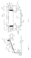
Figur 1(A) : eine Abbildung des Zustands, in dem bei einer Herstellungsvorrichtung für Thermopapier kein Schutzstrich ausgegeben wird, in einer Draufsicht, bei der zum leichteren Verständnis der Vorhangkopf für die Schutzschicht nicht dargestellt ist, -
Figur 1(B) : eine Seitenansicht (Schnittzeichnung entlang Pfeile B-B). -
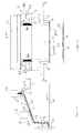
Figur 2(A) : eine Abbildung des Zustands, in dem bei der Herstellungsvorrichtung für Thermopapier der Schutzstrich ausgegeben wird, in einer Draufsicht, bei der zum leichteren Verständnis der Vorhangkopf für die Schutzschicht nicht dargestellt ist, -
Figur 2(B) : eine Seitenansicht (Schnittzeichnung entlang Pfeile B-B), - Figur 2(C): eine Querschnittszeichnung (Schnittzeichnung entlang Pfeile C-C), welche die Beziehung zwischen wärmeempfindlicher Schicht und Schutzschicht auf der Oberfläche der Bahn darstellt,
-
Figur 3 : ein Grundriss, welcher die Beziehung zwischen Unterkante der Kantenführung auf der Platte und des Auftreffpunkts des Schutzstriches, welcher von dem Vorhangkopf für die Schutzschicht ausgegeben wird, auf der Führungsplatte darstellt.
-
FIG. 1 (A) : Imaging in which at a manufacturing apparatus for thermal paper no guard bar output of the state, in a plan view in which is not shown for easier understanding of the curtain head for the protective layer, -
FIG. 1 (B) Is a side view (sectional view along arrows BB). -
Figure 2 (A) : A picture in the output in the production apparatus for thermal paper of the guard bar of the state, is in a plan view, in the not shown for ease of understanding of the curtain head for the protective layer, -
FIG. 2 (B) Is a side view (sectional view along arrows BB), - Figure 2 (C) is a cross-sectional drawing (cross-sectional view along arrows CC) showing the relationship between heat-sensitive layer and protective layer on the surface of the web.
-
FIG. 3 : A plan view, which represents the relationship between the lower edge of the edge guide to the plate and the impact point of the guard bar, which is output from the curtain head to the protective layer on the guide plate.
In diesen Abbildungen werden übrigens die gleichen Teile mit den gleichen Bezeichnungen bezeichnet, wie in der
In diesen Abbildungen ist mit 1a der Vorhangkopf bezeichnet für ein erstes Auftragsmedium ta für eine erste Schicht ca, d.h. für eine wärmeempfindliche Schicht sb. Der Vorhangkopf 1a ist einem zweiten Vorhangkopf 1b für ein zweites Auftragsmedium tb, bzw. für eine zweite Schicht cb, bzw. für eine Schutzschicht sb vorgelagert angeordnet.In these figures, 1a denotes the curtain head for a first coating medium ta for a first layer ca, i. for a heat-sensitive layer sb. The
Mit 2 ist eine Führungsplatte bezeichnet, welche die Medien, welche aus diesen Vorhangköpfen 1a, 1b stammen auf deren Schräge 2a aufnimmt und sie entlang der Schrägen 2a nach unten fließen lässt. Von einer nach unten gerichteten Unterkante (Abrisskante) der Vorhangführung 2b gelangen die Medien ta, tb als fallender Strichvorhang c auf die Oberfläche der Bahn w.Denoted by 2 is a guide plate which receives the media originating from these
Die Oberkante der Führungsplatte 2 verfügt über einen umgebogenen Teil 2c mit einem Gradienten, welcher umgekehrt ist zu der Schräge 2a, entlang der der aufzutragende Strich fließt.The upper edge of the
Mit 9 ist eine Vorrichtung zur Einstellung der Strichbreite bezeichnet. Die Vorrichtung 9 ist unterhalb des Vorhangkopfes 1 a für die wärmeempfindliche Schicht angeordnet und ist symmetrisch angeordnet zu den Flächen (senkrechte Flächen inklusive der Mittellinie c1 der Streichmaschine) an den beiden Enden der vorgelagerten Führungsplatte 2, deren Position in der Breite verstellbar ist und deren Oberfläche einen zum Gradienten der Führungsplatte 2 entgegen gesetzten Gradienten hat, auf der der mittlere Teil tac des Striches ta der wärmeempfindlichen Schicht, welcher von dem Vorhangkopf 1a für die wärmeempfindliche Schicht auf der Führungsplatte 2 ausgegeben wird, fließt und auf dem der Teil der beiden Enden tae des ersten Auftragsmediums ta der wärmeempfindlichen Schicht, welche vom Vorhangkopf 1a für die wärmeempfindliche Schicht auf der Führungsplatte 2 ausgegeben wird und auf deren Oberfläche in entgegengesetzter Richtung zum Fluss auf der Führungsplatte 2 fließt.With a device 9 for adjusting the stroke width is designated. The Device 9 is disposed below the
Die Vorrichtung 9 zur Einstellung der Strichbreite verfügt über ein Paar Kantenführungen 3, welche sich von der Oberkante der Führungsplatte 2 nach unten hin erstrecken, zu den Flächen an der Innenseite parallel sind und auch zur Mittellinie c1 der Streichmaschine parallel sind. Die Kantenführungen 3 liegen an der Oberfläche der Führungsplatte 2 an und sind an ihrer Unterkante spitz geformt. Außerdem ist ein paralleles Paar Hilfsführungen 4 vorgesehen, welche im Bereich der Oberkanten der Kantenführungen 3 der betreffenden Platte fest montiert sind und welche von außen gesehen keilförmig sind. Deren Oberfläche hat einen Gradienten, welcher entgegen gesetzt ist zum Gradienten der Führungsplatte 2. Zusätzlich ist ein paralleles Paar Teilungsplatten 5 vorhanden, welche fest auf der Oberfläche der betreffenden Hilfsführungen 4 montiert sind und deren Oberfläche einen Gradienten hat, der gleich ist wie der Gradient der Oberfläche der Hilfsführungen 4. Im Bereich der Unterkante 3a der Kantenführungen 3 auf der Führungsplatte ist deren Dicke reduziert, wie in
Die Flächen der Innenseiten der Kantenführungen 3 auf der Führungsplatte, die Flächen der Innenseiten der Hilfsführungen 4 und die Flächen der Innenseiten der Trennplatte 5 bilden, wie in
Mit 6 ist eine Vorrichtung zur Positionierung bezeichnet. Mit dieser Vorrichtung 6 wird die Einstellung der Position der Vorrichtung 9 zur Einstellung der Strichbreite in Querrichtung vorgenommen. Die Vorrichtung 6 zur Positionierung besteht aus Schraubenbolzen 6a, welche an den Seitenflächen der Außenseiten der Kantenführungen 3 auf der Platte drehbar montiert sind und besteht aus Mutterelementen 6b, die mit den betreffenden Schraubenbolzen 6a formschlüssig verbunden sind und gleichzeitig an den Endflächen der Führungsplatte 2 fest montiert sind.6 denotes a device for positioning. With this
Die Breite des Auftragsmediums bzw. Striches tb, welcher von dem Vorhangkopf 1b für die Schutzschicht ausgegeben wird, ist größer als die größte Breite zwischen den Flächen 9a der Innenflächen der Vorrichtung 9 zur Einstellung der Strichbreite.The width of the coating medium tb discharged from the
Die Auftreffposition X des zweiten Mediums tb, welches vom zweiten Vorhangkopf 1b für die Schutzschicht ausgegeben wird, befindet sich auf der Führungsplatte 2, wie in
Nachfolgend wird die Funktionsweise der Ausgestaltung des vorliegenden Ausführungsbeispiels erläutert.Hereinafter, the operation of the embodiment of the present embodiment will be explained.
Der Strich ta der wärmeempfindlichen Schicht, welcher von dem Vorhangkopf 1a für die wärmeempfindliche Schicht nach unten hin über die gesamte Breite ausgegeben wird, wird durch die Einheit der Vorrichtung 9 zur Einstellung der Strichbreite, welche darunter angeordnet ist, in einen mittleren Teil tac und einen Teil tae für beide Seiten unterteilt. D.h. der Teil tae für beide Seiten des ausgegebenen Mediums ta der wärmeempfindlichen Schicht trifft auf die Trennplatte 5, welche über einen zur Führungsplatte 2 entgegen gesetzten Gradient hat, fließt auf der Trennplatte 5 nach unten und wird durch die Farbwanne 7 aufgefangen. Anderseits wird der mittlere Teil tac des ausgegebenen Strichs ta so wie er ist nach unten geleitet, trifft im Bereich der Oberkante der Führungsplatte 2 auf, fließt nach unten entlang ihrer Schräge 2a und bewegt sich von der nach unten weisenden Vorhangführung 2b als Strichvorhang c auf die Oberfläche der Bahn w. Dabei bilden für den mittlere Teil tac des Striches ta die Fläche der Innenseite der Kantenführung 3 auf der Platte der Vorrichtung zur Einstellung der Strichbreite, die Fläche der Innenseite derThe line ta of the heat-sensitive layer, which is discharged from the curtain-
Hilfsführung 4 und die Flächen der Innenseite der Trennplatte 5 eine einheitliche senkrechte Führungsfläche 9a, so dass die Seitenflächen des mittleren Teils tac durch diese senkrechte Führungsfläche 9a geführt wird und so auf die Schräge 2a der Führungsplatte 2 ankommt. Auf der Schräge 2a wird der Fluss des Strichs tac der wärmeempfindlichen Schicht durch die Fläche der Innenseite der Kantenführung 3 auf der Platte geführt. Folglich wird bis zur Unterkante 3a der Kantenführung 3 auf der Platte kein Einziehen verursacht.Auxiliary guide 4 and the surfaces of the inside of the partition plate 5 a uniform
Bei dem Fluss des Mediums für die wärmeempfindlichen Schicht auf der Schräge 2a der Führungsplatte 2 kommt es anfänglich unmittelbar nach dem Verlassen der Unterkante 3a der Kantenführung 3 auf der Platte zum Einziehen. Aber die Auftreffposition X des Auftragsmediums ta auf der Führungsplatte 2 befindet sich etwas (z.B. 1 bis 2 mm) vor der Unterkante 3a der Kantenführung 3 auf der Platte oder etwas (z.B. 1 bis 2 mm) dahinter, so dass der Fluss des Mediums ta auf der Schräge 2a der Führungsplatte 2 noch bevor feststeht, ob es zu einem Einziehen kommt oder nicht, durch die Führungsplatte 2 und den Fluss des Strichs tb der Schutzschicht eingeengt. Dadurch kommt es letztendlich zu keinem Einziehen mit Randverdickung der ersten Schicht ta bzw. caIn the flow of the medium for the heat-sensitive layer on the Slant 2a of the
Es ist möglich, eine Positionierung der Bahn w und des Vorhangs ca des Mediums ta für die wärmeempfindliche Schicht durch Erkennen des Schlingerns der Bahn und der damit in Verbindung stehenden Bewegung der Einstellvorrichtung 9 der Strichbreite automatisch auszuführen. Darüber hinaus hat dies die Wirkung, dass das Einziehen, welches an den Kanten des Mediums ta für die wärmeempfindliche Schicht durch die Oberflächenspannung entsteht, verhindert werden kann.It is possible to automatically perform positioning of the web w and the curtain ca of the medium ta for the heat-sensitive layer by recognizing the lurching of the web and the related movement of the adjusting device 9 of the line width. In addition, this has the effect of preventing the entanglement caused by the surface tension at the edges of the heat-sensitive layer medium ta.
Da die wärmeempfindliche Schicht sa auf der Oberfläche der Bahn w vollkommen durch die Schutzschicht sb zur Gänze bedeckt ist (auch wenn die Breite des Striches tb, der von dem Vorhangkopf 1b für die Schutzschicht ausgegeben wird, größer ist als die größte Breite zwischen den Flächen 9a an der Innenseite der Vorrichtung zur Einstellung der Strichbreite 9) kommt es zu keiner direkten Berührung der wärmeempfindlichen Schicht sa mit einer bei der Herstellung der Thermopapierbahn vorhanden Tuchpresswalze und somit tritt das Problem der Verschmutzung der Walzenoberfläche nicht auf.Since the heat-sensitive layer sa on the surface of the web w is completely covered completely by the protective layer sb (even if the width of the stroke tb output from the protective-
Die vorliegende Erfindung ist nicht beschränkt auf die Ausgestaltung in der oben beschriebenen Ausführung, sondern sie kann auch geändert werden, solange die Hauptinhalte der Erfindung nicht verletzt werden. Es wurde z.B. eine Kombination aus Schraubenbolzen 6a und Mutterelement 6b für die Positionierungsvorrichtung 6 beschrieben, aber es können beispielsweise auch eine Kombination mit einer Zahnstange oder ein Linearmotor verwendet werden.The present invention is not limited to the configuration in the above-described embodiment, but it may be changed. as long as the main contents of the invention are not violated. For example, a combination of bolts 6a and
- 11
- VorhangstreichmaschineCurtain coater
- 1 a1 a
- Vorhangkopf für die wärmeempfindliche SchichtCurtain head for the heat-sensitive layer
- 1 b1 b
- Vorhangkopf für die SchutzschichtCurtain head for the protective layer
- 22
- Führungsplatteguide plate
- 2a2a
- Schrägeslope
- 2b2 B
- Vorhangführungcurtain guide
- 2c2c
- umgebogener Teilbent part
- 33
- Kantenführung auf der FührungsplatteEdge guide on the guide plate
- 3a3a
- Unterkantelower edge
- 44
- Hilfsführungauxiliary guide
- 55
- Teilungs- bzw. TrennplatteDividing or separating plate
- 66
- Positionierungsvorrichtungpositioning device
- 6a6a
- Schraubenbolzenbolt
- 6b6b
- Mutterelementnut element
- 77
- Farbwannepaint tray
- 88th
- Kantenführungedge guide
- 99
- Vorrichtung zur Einstellung der StrichbreiteDevice for adjusting the stroke width
- 9a9a
- senkrechte Führungsflächevertical guide surface
- cc
- Vorhangcurtain
- caca
- erste Vorhangschichtfirst curtain layer
- cbcb
- zweite Vorhangschichtsecond curtain layer
- dathere
- Auftragsschlitzapplication slot
- dbdb
- Auftragschlitzapplication slot
- saSat.
- untere SchichtLower class
- sbsb
- obere Schicht bzw. Schutzschichtupper layer or protective layer
- tata
- erstes Auftragsmediumfirst application medium
- tbtb
- zweites Auftragsmediumsecond application medium
- tactac
- mittlerer Teilmiddle part
- taetae
- seitlicher Teillateral part
- XX
- Auftreffpositionlanding
Claims (14)
dadurch gekennzeichnet, dass,
eine Vorrichtung (9)zur Einstellung der Auftragsbreite für die erste Vorhangschicht (ca) vorgesehen ist, welche so angeordnet ist, dass sie sich unterhalb des ersten Vorhangkopfs (1a) für die erste Schicht (ca, sa)befindet und dem seitlichen oberen Bereich der Führungsplatte (2) zugeordnet ist, so dass ein mittlerer Teil (tac) der ersten Vorhangschicht (ca), welche vom Vorhangkopf (1a) abgegeben wird von seitlichen Teilen(tae) derselben Schicht (ca) abtrennbar ist, wodurch der mittlere Teil (tac) auf der Oberfläche der Führungsplatte (2)hinabgleitet und die seitlichen Teile (tae) in entgegen gesetzter Richtung wie der Fluss des mittleren Teils (tac) abfließen.Curtain coater (1) for coating a running paper, cardboard or other fibrous web (w), comprising a first curtain head (1a) for dispensing a first application medium (ta) for a first curtain layer (ca) and comprising a second curtain head (1b) for dispensing a second coating medium (tb) for a second curtain layer (cb, sb), wherein the first curtain head (1a) precedes the second curtain head (1b), and both curtain heads (1a, 1b) retract their curtain layers (ca, cb) directed downwards, and comprising an inclined guide plate (2), which is arranged below the curtain heads (1a, 1 b) and receives the curtain layers emitted curtain layers and flow down along its slope (2a), wherein the curtain layers (approx , cb) fall from a curtain guide (2b) onto the surface of the web (w) to be coated in the form of a curtain (c),
characterized in that
a device (9) for adjusting the application width for the first curtain layer (ca) is provided, which is arranged so that it is located below the first curtain head (1a) for the first layer (ca, sa) and the lateral upper region of Guide plate (2) is assigned, so that a central part (tac) of the first curtain layer (ca), which is discharged from the curtain head (1a) is separable from lateral parts (tae) of the same layer (ca), whereby the middle part (tac ) slides down on the surface of the guide plate (2) and the lateral parts (tae) flow in the opposite direction as the flow of the middle part (tac).
dadurch gekennzeichnet, dass
die Vorrichtung (9) zur Einstellung der Auftragsbreite des ersten Auftragsmediums (ca) ein Paar Kantenführungen (3), ein Paar Hilfsführungen (4) und ein Paar Teilungsplatten (5) aufweist, wobei jeweils die Fläche der Innenseite der Kantenführung (3), die Fläche der Innenseite der Hilfsführung (4) und die Fläche der Innenseite der Teilungsplatte 85) eine einheitliche, senkrechte Führungsfläche (9a) für den mittleren Teil (tac)des ersten Auftragsmediums (ca9 bzw. für die erste Schicht (sa) bildet.Curtain coater (1) according to claim 1,
characterized in that
the device (9) for adjusting the application width of the first application medium (ca) comprises a pair of edge guides (3), a pair of auxiliary guides (4) and a pair of partition plates (5), wherein in each case the surface of the inside of the edge guide (3) Face of the inside of the auxiliary guide (4) and the surface of the inside of the partition plate 85) forms a uniform, vertical guide surface (9a) for the middle part (tac) of the first application medium (ca9 or for the first layer (sa).
dadurch gekennzeichnet, dass
die Kantenführungen (3) jeweils an der Seite der Führungsplatte (2) anliegen und sich von deren oberen bereich nach unten hin erstrecken, wobei die Innenseiten der Kantenführungen (3) parallel zueinander und auch parallel zu einer gedachten Mittellinie (c1) der Vorhangstreichmaschine (1) sind.Curtain coater (1) according to claim 1 or 2,
characterized in that
the edge guides (3) in each case rest on the side of the guide plate (2) and extend downwards from the upper region, the inner sides of the edge guides (3) being parallel to one another and also parallel to an imaginary center line (c1) of the curtain coater (1 ) are.
dadurch gekennzeichnet, dass
die Kantenführungen (3) jeweils eine spitze Unterkante aufweisen.Curtain coater (1) according to at least one of the preceding claims,
characterized in that
the edge guides (3) each have a pointed lower edge.
die Hilfsführungen (4) auf die Oberkanten der Kantenführungen (3) aufgesetzt und mit diesen fest verbunden sind.Curtain coater (1) according to at least one of the preceding claims, characterized in that
the auxiliary guides (4) are placed on the upper edges of the edge guides (3) and firmly connected thereto.
dadurch gekennzeichnet, dass
die Oberflächen der seitlichen Kantenführungen (3) in dieselbe Richtung geneigt sind, wie die Führungsplatte (2).Curtain coater according to at least one of the preceding claims,
characterized in that
the surfaces of the lateral edge guides (3) are inclined in the same direction as the guide plate (2).
dadurch gekennzeichnet, dass
die seitlichen Teilungsplatten (5) jeweils fest auf der Oberfläche der betreffenden Hilfsführungen (4) montiert sind, wobei die Oberflächen der Hilfsführungen (4)in dieselbe Richtung geneigt sind wie die Oberflächen der Hilfsführungen (4).Curtain coater according to at least one of the preceding claims,
characterized in that
the lateral partition plates (5) are respectively fixedly mounted on the surface of the respective auxiliary guides (4), the surfaces of the auxiliary guides (4) being inclined in the same direction as the surfaces of the auxiliary guides (4).
die Teilungsplatten (5) und die Oberflächen der Hilfsführungen (4) entgegengesetzt geneigt sind zu den Kantenführungen (3) und der Führungsplatte (2).Curtain coater according to at least one of the preceding claims, characterized in that
the partition plates (5) and the surfaces of the auxiliary guides (4) are inclined in opposite directions to the edge guides (3) and the guide plate (2).
dadurch gekennzeichnet, dass
unterhalb der Teilungsplatten (5) eine Auffangwanne (7) angeordnet ist, die die seitlichen Teile (tae) des ersten Auftragsmediums (ca) auffängt, welche von den Teilungsplatten (5) abfließen, wobei diese seitlichen Teile entgegengesetzt zur Fließrichtung des mittleren Auftragsmediumsteiles (tac) auf der Führungsplatte (2)fließen.Curtain coater according to at least one of the preceding claims,
characterized in that
below the dividing plates (5) a collecting trough (7) is arranged, which absorbs the lateral parts (tae) of the first application medium (ca), which flow away from the dividing plates (5), these lateral parts opposite to the flow direction of the middle application medium part (tac ) on the guide plate (2).
dadurch gekennzeichnet, dass
zur Einstellung der Auftragsbreite des Auftragsmediums eine aus einem Schraubenbolzen (6a) und einem Mutterelement (6b)bestehende Positionierungsvorrichtung (6) vorgesehen ist, wobei jeweils der Schraubenbolzen (6a) an der seitlichen Außenfläche der Kantenführung (3) und oberhalb der Führungsplatte (2) drehbar befestigt ist, und wobei das Mutterelement (6b) mit dem betreffenden Schraubenbolzen (6a) formschlüssig verbunden ist, und gleichzeitig an der Seitenfläche der Führungsplatte (2) angebracht ist.Curtain coater according to at least one of the preceding claims,
characterized in that
for adjusting the application width of the application medium, a positioning device (6) consisting of a screw bolt (6a) and a nut element (6b) is provided, wherein each of the bolts (6a) on the lateral outer surface of the edge guide (3) and above the guide plate (2) is rotatably mounted, and wherein the nut member (6b) with the respective bolt (6a) is positively connected, and at the same time on the side surface of the Guide plate (2) is mounted.
dadurch gekennzeichnet, dass
ein zweites paar Hilfsführungen (8) vorgesehen ist, zur Führung des Vorhangs (c) der von der Vorhangführung (2a) aus bis auf die Oberfläche der Bahn (w) reicht.Curtain coater according to at least one of the preceding claims,
characterized in that
a second pair of auxiliary guides (8) is provided for guiding the curtain (c) extending from the curtain guide (2a) to the surface of the web (w).
dadurch gekennzeichnet, dass
das erste Auftragsmedium (ta) eine wärmeempfindliche untere Schicht (sa) und das zweite Auftragsmedium (tb) eine obere Schutzschicht (sb) auf der Faserstoffbahn (w) bildet.Curtain coater according to at least one of the preceding claims,
characterized in that
the first application medium (ta) forms a heat-sensitive lower layer (sa) and the second application medium (tb) forms an upper protective layer (sb) on the fibrous web (w).
dadurch gekennzeichnet, dass
die Schutzschicht (sb) die wärmeempfindliche Schicht (sa) überdeckt bzw. größer ist als die Breite des ersten Auftragsmediums (ta) zwischen den parallelen senkrechten Führungsflächen (9a).Curtain coater according to at least one of the preceding claims,
characterized in that
the protective layer (sb) covers the heat-sensitive layer (sa) larger than the width of the first coating medium (ta) between the parallel vertical guide surfaces (9a).
gekennzeichnet durch
ihre Verwendung bei der Herstellung von Thermopapier.Curtain coater according to at least one of the preceding claims,
marked by
their use in the production of thermal paper.
Applications Claiming Priority (1)
| Application Number | Priority Date | Filing Date | Title |
|---|---|---|---|
| JP2007189596A JP5228226B2 (en) | 2007-07-20 | 2007-07-20 | Thermal paper manufacturing equipment |
Publications (2)
| Publication Number | Publication Date |
|---|---|
| EP2017012A2 true EP2017012A2 (en) | 2009-01-21 |
| EP2017012A3 EP2017012A3 (en) | 2009-02-25 |
Family
ID=39846622
Family Applications (1)
| Application Number | Title | Priority Date | Filing Date |
|---|---|---|---|
| EP08160076A Ceased EP2017012A3 (en) | 2007-07-20 | 2008-07-10 | Curtain coating machine |
Country Status (2)
| Country | Link |
|---|---|
| EP (1) | EP2017012A3 (en) |
| JP (1) | JP5228226B2 (en) |
Cited By (1)
| Publication number | Priority date | Publication date | Assignee | Title |
|---|---|---|---|---|
| EP2157240A3 (en) * | 2008-08-21 | 2010-11-24 | Voith Patent GmbH | Curtain application device |
Families Citing this family (2)
| Publication number | Priority date | Publication date | Assignee | Title |
|---|---|---|---|---|
| JP5338427B2 (en) * | 2009-03-30 | 2013-11-13 | 王子ホールディングス株式会社 | Curtain coating equipment |
| JP7093600B2 (en) * | 2020-11-06 | 2022-06-30 | 大阪シーリング印刷株式会社 | Thermal recording body |
Citations (1)
| Publication number | Priority date | Publication date | Assignee | Title |
|---|---|---|---|---|
| JP2006249611A (en) | 2005-03-10 | 2006-09-21 | Toray Ind Inc | Fabric having excellent flame retardancy and method for producing the same |
Family Cites Families (16)
| Publication number | Priority date | Publication date | Assignee | Title |
|---|---|---|---|---|
| DE2351369C2 (en) * | 1973-10-12 | 1983-05-11 | CIBA-GEIGY AG, 4002 Basel | Coating device |
| US4559896A (en) * | 1983-09-15 | 1985-12-24 | Ciba Geigy Corporation | Coating apparatus |
| JP2782531B2 (en) * | 1989-06-19 | 1998-08-06 | 富士写真フイルム株式会社 | Curtain coating width changing device |
| DE69115470T2 (en) * | 1991-06-18 | 1996-08-01 | Agfa Gevaert Nv | Curtain coater |
| JP3193075B2 (en) * | 1991-07-05 | 2001-07-30 | 三菱製紙株式会社 | Manufacturing method of coated paper |
| JPH07171467A (en) * | 1991-09-02 | 1995-07-11 | Fuji Photo Film Co Ltd | Coating method and device therefor |
| JP2584923Y2 (en) * | 1992-04-17 | 1998-11-11 | 石川島播磨重工業株式会社 | Coating equipment |
| US5683750A (en) * | 1996-07-30 | 1997-11-04 | Eastman Kodak Company | High speed coating starts for multiple layer coatings using a temporary top coat |
| JP3621204B2 (en) * | 1996-08-20 | 2005-02-16 | 三菱製紙株式会社 | Curtain coating apparatus and coating method |
| DE19735588A1 (en) * | 1997-04-21 | 1999-02-18 | Jagenberg Papiertech Gmbh | Coating a moving web |
| DE10316999A1 (en) * | 2003-04-11 | 2004-10-28 | Bachofen & Meier Ag | Device for coating a running material web |
| DE10320146A1 (en) * | 2003-05-06 | 2004-11-25 | Voith Paper Patent Gmbh | Multi-layer application device for applying application medium by means of at least one multi-layer curtain or veil |
| JP2006055703A (en) * | 2004-08-18 | 2006-03-02 | Mitsubishi Paper Mills Ltd | Curtain coating apparatus and curtain coating method |
| JP4746894B2 (en) * | 2005-03-14 | 2011-08-10 | ボイス ペ−パ− パテント ゲ−エムベ−ハ− | Coating equipment |
| DE102005035317A1 (en) * | 2005-07-28 | 2007-02-01 | Voith Patent Gmbh | Method for directly applying layers of a liquid-to-pasty medium to a paper, cardboard or other fibrous strip comprises releasing the media separately from one another from chambers and combining to form a curtain |
| JP5239008B2 (en) * | 2007-07-13 | 2013-07-17 | ボイス パテント ゲーエムベーハー | Coating width adjustment device for coating machine |
-
2007
- 2007-07-20 JP JP2007189596A patent/JP5228226B2/en not_active Expired - Fee Related
-
2008
- 2008-07-10 EP EP08160076A patent/EP2017012A3/en not_active Ceased
Patent Citations (1)
| Publication number | Priority date | Publication date | Assignee | Title |
|---|---|---|---|---|
| JP2006249611A (en) | 2005-03-10 | 2006-09-21 | Toray Ind Inc | Fabric having excellent flame retardancy and method for producing the same |
Cited By (1)
| Publication number | Priority date | Publication date | Assignee | Title |
|---|---|---|---|---|
| EP2157240A3 (en) * | 2008-08-21 | 2010-11-24 | Voith Patent GmbH | Curtain application device |
Also Published As
| Publication number | Publication date |
|---|---|
| EP2017012A3 (en) | 2009-02-25 |
| JP2009023250A (en) | 2009-02-05 |
| JP5228226B2 (en) | 2013-07-03 |
Similar Documents
| Publication | Publication Date | Title |
|---|---|---|
| EP1861207B1 (en) | Application device | |
| EP2146003A2 (en) | Curtain application device | |
| EP0826824B1 (en) | Coating device for applying directly or indirectly a fluid or pasty coating colour onto a moving web, especially of paper or board | |
| DE3907846B4 (en) | Coating apparatus and method for applying a coating medium to a continuous flexible carrier | |
| DE68919699T2 (en) | CURTAIN COATING, METHOD AND APPARATUS. | |
| EP0855464A2 (en) | Apparatus and process for applying directly or indirectly a liquid or pasty medium onto a moving web | |
| EP2017012A2 (en) | Curtain coating machine | |
| CH621269A5 (en) | Process and apparatus for coating an object by the curtain-coating method | |
| EP1239974B1 (en) | Device for coating a running material web | |
| WO2010091986A1 (en) | Curtain application unit | |
| DE2812946C3 (en) | Device for coating an endless web | |
| CH666835A5 (en) | DEVICE FOR OPTIONALLY SINGLE OR DOUBLE-SIDED COATING OF A RUNNING PAPER, AND METHOD FOR OPERATING THE DEVICE. | |
| EP2014376A2 (en) | Curtain coating machine | |
| EP1782891B1 (en) | Method of and apparatus for deposition of at least two layers of coating colour onto the surface of a moving web, in particular a paper or cardboard web | |
| EP1861206B1 (en) | Curtain application unit | |
| EP2111925A1 (en) | Curtain application device | |
| EP2067531A2 (en) | Edge guide | |
| EP2082811A2 (en) | Multiple curtain painting device | |
| EP3006115B1 (en) | Method and device for curtain coating | |
| EP2409781B1 (en) | Curtain coating apparatus | |
| EP1779935A2 (en) | Coating apparatus and method | |
| EP2083119B1 (en) | Curtain application device | |
| DE3438181A1 (en) | Edge seal for a surface-application device for coating moving webs of material | |
| EP1749585A2 (en) | Method of applying a coating | |
| WO2014118336A1 (en) | Device for applying a coating, in particular adhesive, preferably glue, to a material web |
Legal Events
| Date | Code | Title | Description |
|---|---|---|---|
| PUAI | Public reference made under article 153(3) epc to a published international application that has entered the european phase |
Free format text: ORIGINAL CODE: 0009012 |
|
| AK | Designated contracting states |
Kind code of ref document: A2 Designated state(s): AT BE BG CH CY CZ DE DK EE ES FI FR GB GR HR HU IE IS IT LI LT LU LV MC MT NL NO PL PT RO SE SI SK TR |
|
| AX | Request for extension of the european patent |
Extension state: AL BA MK RS |
|
| PUAL | Search report despatched |
Free format text: ORIGINAL CODE: 0009013 |
|
| AK | Designated contracting states |
Kind code of ref document: A3 Designated state(s): AT BE BG CH CY CZ DE DK EE ES FI FR GB GR HR HU IE IS IT LI LT LU LV MC MT NL NO PL PT RO SE SI SK TR |
|
| AX | Request for extension of the european patent |
Extension state: AL BA MK RS |
|
| 17Q | First examination report despatched |
Effective date: 20090918 |
|
| AKX | Designation fees paid |
Designated state(s): AT BE BG CH CY CZ DE DK EE ES FI FR GB GR HR HU IE IS IT LI LT LU LV MC MT NL NO PL PT RO SE SI SK TR |
|
| 17P | Request for examination filed |
Effective date: 20090825 |
|
| STAA | Information on the status of an ep patent application or granted ep patent |
Free format text: STATUS: THE APPLICATION HAS BEEN REFUSED |
|
| 18R | Application refused |
Effective date: 20100507 |