EP2017034A1 - Verfahren, System und Vorrichtung zum Halten eines Werkstücks - Google Patents
Verfahren, System und Vorrichtung zum Halten eines Werkstücks Download PDFInfo
- Publication number
- EP2017034A1 EP2017034A1 EP07112801A EP07112801A EP2017034A1 EP 2017034 A1 EP2017034 A1 EP 2017034A1 EP 07112801 A EP07112801 A EP 07112801A EP 07112801 A EP07112801 A EP 07112801A EP 2017034 A1 EP2017034 A1 EP 2017034A1
- Authority
- EP
- European Patent Office
- Prior art keywords
- ball
- workpiece
- socket
- workpiece holding
- holding device
- Prior art date
- Legal status (The legal status is an assumption and is not a legal conclusion. Google has not performed a legal analysis and makes no representation as to the accuracy of the status listed.)
- Withdrawn
Links
Images



Classifications
-
- B—PERFORMING OPERATIONS; TRANSPORTING
- B23—MACHINE TOOLS; METAL-WORKING NOT OTHERWISE PROVIDED FOR
- B23Q—DETAILS, COMPONENTS, OR ACCESSORIES FOR MACHINE TOOLS, e.g. ARRANGEMENTS FOR COPYING OR CONTROLLING; MACHINE TOOLS IN GENERAL CHARACTERISED BY THE CONSTRUCTION OF PARTICULAR DETAILS OR COMPONENTS; COMBINATIONS OR ASSOCIATIONS OF METAL-WORKING MACHINES, NOT DIRECTED TO A PARTICULAR RESULT
- B23Q1/00—Members which are comprised in the general build-up of a form of machine, particularly relatively large fixed members
- B23Q1/0063—Connecting non-slidable parts of machine tools to each other
-
- B—PERFORMING OPERATIONS; TRANSPORTING
- B23—MACHINE TOOLS; METAL-WORKING NOT OTHERWISE PROVIDED FOR
- B23Q—DETAILS, COMPONENTS, OR ACCESSORIES FOR MACHINE TOOLS, e.g. ARRANGEMENTS FOR COPYING OR CONTROLLING; MACHINE TOOLS IN GENERAL CHARACTERISED BY THE CONSTRUCTION OF PARTICULAR DETAILS OR COMPONENTS; COMBINATIONS OR ASSOCIATIONS OF METAL-WORKING MACHINES, NOT DIRECTED TO A PARTICULAR RESULT
- B23Q1/00—Members which are comprised in the general build-up of a form of machine, particularly relatively large fixed members
- B23Q1/25—Movable or adjustable work or tool supports
- B23Q1/44—Movable or adjustable work or tool supports using particular mechanisms
- B23Q1/50—Movable or adjustable work or tool supports using particular mechanisms with rotating pairs only, the rotating pairs being the first two elements of the mechanism
- B23Q1/54—Movable or adjustable work or tool supports using particular mechanisms with rotating pairs only, the rotating pairs being the first two elements of the mechanism two rotating pairs only
- B23Q1/545—Movable or adjustable work or tool supports using particular mechanisms with rotating pairs only, the rotating pairs being the first two elements of the mechanism two rotating pairs only comprising spherical surfaces
-
- B—PERFORMING OPERATIONS; TRANSPORTING
- B25—HAND TOOLS; PORTABLE POWER-DRIVEN TOOLS; MANIPULATORS
- B25B—TOOLS OR BENCH DEVICES NOT OTHERWISE PROVIDED FOR, FOR FASTENING, CONNECTING, DISENGAGING, OR HOLDING
- B25B5/00—Clamps
- B25B5/16—Details, e.g. jaws, jaw attachments
- B25B5/163—Jaws or jaw attachments
-
- F—MECHANICAL ENGINEERING; LIGHTING; HEATING; WEAPONS; BLASTING
- F16—ENGINEERING ELEMENTS AND UNITS; GENERAL MEASURES FOR PRODUCING AND MAINTAINING EFFECTIVE FUNCTIONING OF MACHINES OR INSTALLATIONS; THERMAL INSULATION IN GENERAL
- F16M—FRAMES, CASINGS OR BEDS OF ENGINES, MACHINES OR APPARATUS, NOT SPECIFIC TO ENGINES, MACHINES OR APPARATUS PROVIDED FOR ELSEWHERE; STANDS; SUPPORTS
- F16M11/00—Stands or trestles as supports for apparatus or articles placed thereon ; Stands for scientific apparatus such as gravitational force meters
- F16M11/02—Heads
- F16M11/04—Means for attachment of apparatus; Means allowing adjustment of the apparatus relatively to the stand
- F16M11/06—Means for attachment of apparatus; Means allowing adjustment of the apparatus relatively to the stand allowing pivoting
- F16M11/12—Means for attachment of apparatus; Means allowing adjustment of the apparatus relatively to the stand allowing pivoting in more than one direction
- F16M11/14—Means for attachment of apparatus; Means allowing adjustment of the apparatus relatively to the stand allowing pivoting in more than one direction with ball-joint
-
- F—MECHANICAL ENGINEERING; LIGHTING; HEATING; WEAPONS; BLASTING
- F16—ENGINEERING ELEMENTS AND UNITS; GENERAL MEASURES FOR PRODUCING AND MAINTAINING EFFECTIVE FUNCTIONING OF MACHINES OR INSTALLATIONS; THERMAL INSULATION IN GENERAL
- F16M—FRAMES, CASINGS OR BEDS OF ENGINES, MACHINES OR APPARATUS, NOT SPECIFIC TO ENGINES, MACHINES OR APPARATUS PROVIDED FOR ELSEWHERE; STANDS; SUPPORTS
- F16M2200/00—Details of stands or supports
- F16M2200/02—Locking means
- F16M2200/021—Locking means for rotational movement
- F16M2200/022—Locking means for rotational movement by friction
Definitions
- the present invention relates to a workpiece holding device, system and method.
- the workpiece For processing, and particularly for machining workpieces, it is generally necessary to hold the workpiece in a fixed position and orientation. Generally, the workpiece is held using one or several devices such as clamps or vices, so as to prevent such movement of the workpiece during a processing step that could disturb the final shape or appearance of the workpiece after the process.
- a particularly flexible type of workpiece holding device is represented by ball-and-socket workpiece holding devices, such as have been disclosed, for instance, in British patent GB 1,014,809 or European patent application EP 0 461 994 A1 .
- Such workpiece holding devices of the state of the art comprise a substantially spherical ball with means for releasably retaining a workpiece, a socket with a first ball-receiving surface and means for mounting said socket on a worktable, and means for releasably clamping said ball against said first ball-receiving surface.
- the ball Before clamping the ball against the ball-receiving surface of the socket, the ball can rotate at least to a certain extent within the socket, thus allowing a user to orient the connecting means and the workpiece connected to it, so as to facilitate the work on said workpiece.
- the ball-and-socket workpiece holding devices of the state of the art do not provide any means for translationally adjusting the position of the ball, to adapt it, for instance, to workpieces with attachment points whose position may vary within certain manufacturing tolerances. While it has been proposed, for instance in EP 0 507 033 A1 , to make the sockets themselves translationally moveable, the need for maintaining the position of the socket stable while the workpiece is processed results in mechanically complicated socket translation and locking devices.
- a first objective of the present invention is thus that of allowing at least limited translational adjustments to the position of the ball, while blocking such adjustments when the ball is clamped.
- said first ball-receiving surface is shaped on a ball-receiving element mounted moveable, within said socket, along at least one axis in a plane substantially perpendicular to its ball clamping force.
- said first ball-receiving surface is substantially conical.
- Such a shape has the advantage of providing a stable seat for the ball, while being comparatively simple to produce.
- said first ball-receiving surface could also be, for instance, a substantially spherical surface with an equal or larger radius than the ball.
- said ball clamping means comprises an internal member and an external member, the external member comprising means for transmitting said ball clamping force to said socket and the internal member comprising a second ball-receiving surface for contacting said ball and clamping said ball between said first and second ball-receiving surfaces.
- the second ball-receiving surface is also preferably conical, although other shapes, such as, for instance, a substantially spherical shape of equal or larger radius than the ball, could also be contemplated alternatively.
- said external member comprises a screw thread
- said socket comprises a screw thread
- said screw threads of the external member and socket can cooperate for connecting the external member and socket and generating said ball clamping force by tightening the connection between them.
- the workpiece holding device of the invention preferably comprises a cover element for protecting the holding device from falling debris, such as, for instance, metal shavings.
- the socket may further comprise means for guiding the movement of said ball receiving element within said socket along a single axis substantially perpendicular to its ball clamping force.
- the socket further comprises means for externally indicating the direction of said single axis, so that a user can know when the socket is mounted in the adequate orientation on the worktable.
- said means for mounting the socket on a worktable comprise a plurality of bolts, such as, for instance, four, arranged around the socket and at least one of these bolts is differently shaped and/or sized to indicate the direction of said single axis.
- a further objective of the present invention is therefore that of isostatically holding a workpiece with at least three attachment points without significantly stressing it even when the relative positions of the attachment points vary within certain manufacturing tolerances.
- the present invention also relates to a workpiece holding system comprising a first and a second of the hereabove described workpiece holding devices, and a third workpiece holding device comprising a substantially spherical ball with means for releasably connecting said substantially spherical ball to a workpiece, a socket with a first ball-receiving surface and means for mounting said socket on a worktable, and means for releasably clamping the ball against said first ball-receiving surface, wherein said first ball-receiving surface is fixed in a plane perpendicular to its ball clamping force.
- the ball receiving element of the first workpiece holding device is mounted moveable, within its socket, in all directions in a plane substantially perpendicular to the direction of its ball clamping force, whereas the ball receiving element of the second workpiece holding device is mounted moveable, within its socket, along a single axis substantially perpendicular to the direction of its ball clamping force.
- the present invention also relates to a method for using this workpiece holding system comprising the following steps:
- first ball-receiving surfaces of the first and second workpiece holding devices can slide laterally within their sockets before the balls are clamped, their positions will adjust to varying relative positions of the attachment points, thus minimizing the internal stresses in the workpiece when the balls are clamped.
- Another objective of the present invention is thus the alleviation of internal stresses between processing steps in the workpiece for achieving a processed workpiece with considerably tighter manufacturing tolerances at lower cost.
- This objective can be achieved by unclamping the balls of the three workpiece holding devices after carrying out at least one first processing step on said workpiece so as to release any internal stresses in the workpiece caused by said at least one first processing step; and clamping the balls again after releasing said internal stresses, so as to fix again the position and orientation of the workpiece before carrying out at least one further processing step on said workpiece.
- separately mounting the balls to the workpiece and the sockets to the worktable before placing the workpiece on the worktable allows a faster workflow. Since the balls of all the workpiece holding devices may be identical or interchangeable, it is possible to keep a stock of workpieces with the balls already attached so as to successively fix them onto the same three sockets on a worktable with minimal work.
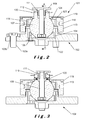
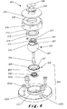
- FIG. 1 An exploded perspective view of a first embodiment of a workpiece holding device 101, showing all its individual components, is illustrated in Figure 1 .
- This workpiece holding device 101 comprises a socket 102 with bolts 103a in bolt-receiving orifices 103b for mounting it onto a worktable (not shown) and a ball-receiving element in the shape of a ring 104 with an inner conical first ball-receiving surface 105 and a retaining member 106.
- the inner conical first ball-receiving surface 105 is shaped so as to accommodate a substantially spherical ball 107 with means for releasably retaining a workpiece.
- these retaining means comprise a T-shaped member 108 attached to the ball 107 with a bolt 109, a top surface 110 of a cylindrical extension 112 of the ball 107 and a key protrusion 111 of said cylindrical extension 112 extending beyond said top surface 110.
- a suitably shaped attachment point on the workpiece can be retained or released by tightening or loosening the bolt 109 so as to close or open the space between the T-shaped member 108 and the top surface 110.
- alternative retaining means such as, for example, clamps or vices, could be contemplated by the skilled person.
- clamping means comprise an external member 113 and an internal member 114.
- the internal member 114 similarly to the ring 104 is ring-shaped with an inner conical second ball-receiving surface 115, so that the ball 107 can be clamped between the first ball-receiving surface 105 and the second ball-receiving surface 115.
- the external member 113 comprises an internal screw thread 116 suitable for threading onto an external screw thread 117 on the socket 102.
- the threaded connection between external member 113 and socket 102 is tightened with a tightening torque resulting on a clamping force between said external member 113 and socket 102.
- the illustrated external member 113 comprises a series of radially arranged orifices 118 for receiving said tightening torque.
- the workpiece holding device 101 further comprises a cover element 119, retained by two spring-loaded balls 120 located in corresponding orifices 121 in the cylindrical extension 112.
- the purpose of this cover element 119 is to protect the elements below it from falling debris, such as metal shavings resulting from machining the workpiece.
- the spring-loaded balls 120 retain the cover element 119 close to the external member 113 in the clamped position, but a circlip 130 in a circular groove 131 around the cylindrical extension 112 ensures that the cover element 119 can not accidentally be removed from the workpiece holding device 101 in its unclamped position.
- ring 104 is mounted moveable within the socket 102.
- Retaining member 106 prevents that the ring 104 be lifted in a vertical direction, but the ring 104 can slide on a surface 122 in all horizontal directions within the confines of the socket 102, adding two degrees of translational freedom to the three degrees of rotational freedom of the ball 107.
- the vertical clamping force acting from the external member 113 through the internal member 114 and onto the ball 107 not only clamps the ball 107 firmly between the internal member 114 and the ring 104, preventing rotation of the ball 107, but also clamps the ring 104 between the ball 107 and surface 122 of the socket 102, preventing lateral movement of ring 104 and thus of ball 107 within the socket 104.
- the internal member 114 Since the internal member 114 is also mounted moveable within the external member 113, it can realign itself with the ring 104 when it is laterally displaced, even if the external member 113 stays aligned with the socket 102.
- the clamping force is transmitted between the external member 113 and the internal member 114 through their correspondent surfaces 123 and 124.
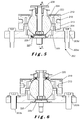
- Figs. 4 to 6 similarly present an alternative embodiment of the workpiece holding device of the invention.
- the ball 207, the clamping means and the cover element 219 are identical to those of the workpiece holding device 101 illustrated in Figs. 1 to 3 .
- the ball 207 also comprises identical means for releasably retaining a workpiece, in the shape of a T-shaped member 208 attached to the ball 207 with a bolt 209, a top surface 210 of a cylindrical extension 212 of the ball 207, and a key protrusion 211 of said cylindrical extension 212 extending beyond said top surface 210.
- the clamping means also comprise identical external and internal members 213, 214 with surfaces 215, 223 and 224, and the cover element 219 is also retained by two identical spring-loaded balls 220 located in corresponding orifices 221 in the cylindrical extension 212 and a circlip 230 in a circular groove 231.
- the socket 202 there are differences in the socket 202.
- the ball-receiving element in the shape of a ring 204 is held down by a different retaining element 206 latched to an elongated guide 225 in the socket.
- This retaining element 206 not only prevents lift-off of the ring 204 from the surface 222 of the socket 202, but also guides its translational movement along a single horizontal axis.
- the ball 207 in this workpiece holding device 201 will thus have a single degree of translational freedom in addition to its three degrees of rotational freedom.
- the retaining element 206 is connected to the ring 204 by a small screw 226 screwed into a small threaded orifice 227 of the ring 204 so as to reach into a circular groove 228 in the retaining element 206 so as to retain it axially while allowing rotational freedom around the vertical axis.
- a small screw 226 screwed into a small threaded orifice 227 of the ring 204 so as to reach into a circular groove 228 in the retaining element 206 so as to retain it axially while allowing rotational freedom around the vertical axis.
- other alternative arrangements should be obvious to the skilled person.
- the socket 202 has two different sets of bolts 203a and 203a' in corresponding bolt-receiving orifices 203b, and 203b' for mounting it onto a worktable (not shown).
- the two orifices 203b are aligned in the direction of the axis of translational freedom of the ring 204 with the inner conical first ball-receiving surface 205.
- each one of the two pairs of orifices 203b, 203b' is adapted to a single one of those two types of bolts 203a, 203a', it will be possible to ensure that the socket 202 can only be mounted onto a worktable with a predetermined orientation.
- the invention also relates to a workpiece holding system comprising several workpiece holding devices.
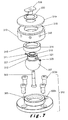
- the workpiece holding system may comprise a first workpiece holding device 101 like the one illustrated in Figs. 1 to 3 , a second workpiece holding device 201 like the one illustrated in Figs. 4 to 6 and a third workpiece holding device 301, which is illustrated in Figs. 7 and 8 .
- This third workpiece holding device 301 is intended to provide a fixed reference point for the position of the workpiece, and is thus similar to workpiece holding devices of the state of the art. Therefore, in this workpiece holding device 301, the inner conical first ball-receiving surface 305 is fixed within the socket 302. However, the ball 307, the clamping means and the cover element 319 are also identical to those of the workpiece holding device 101 illustrated in Figs. 1 to 3 .
- the ball 307 also comprises identical means for releasably retaining a workpiece, in the shape of a T-shaped member 308 attached to the ball 307 with a bolt 309, a top surface 310 of a cylindrical extension 312 of the ball 307, and a key protrusion 311 of said cylindrical extension 312 extending beyond said top surface 310.
- the clamping means also comprise identical external and internal members 313, 314 with surfaces 315, 323 and 324, and the cover element 319 is also retained by two identical spring-loaded balls 320 located in corresponding orifices 321 in the cylindrical extension 312 and a circlip 330 in a circular groove 331.
- the socket 302 has bolts 303a in corresponding orifices 303b for mounting it onto a worktable.
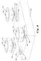
- Figs. 9 to 12 show several steps of a method for using this workpiece holding system.
- the balls 107, 207 and 307, together with their respective clamping means are being attached to the workpiece 901 using their workpiece retaining means.
- Ball 307 is still away from the corresponding attachment point 902.
- Its bolt 309 is loose, so that the T-shaped member 308 hangs well apart from the retaining ring 310.
- the T-shaped member 208 of ball 207 is being introduced, in the same open state, into the channel 903 of its attachment point 902.
- the T-shaped member 108 of ball 107 has already been introduced into the channel 903 of its attachment point 902 and its bolt 109 tightened, so that ball 107 is attached to the workpiece 901.
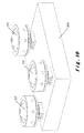
- Fig. 10 the balls 107, 207 and 307, together with their respective clamping means, are being attached to the workpiece 901 using their workpiece retaining means.
- Ball 307 is still away from the corresponding attachment point 902.
- Fig. 11 shows the workpiece 901, with the balls 107, 207 and 307 and their respective clamping means, hovering over a worktable 905, on which the sockets 102, 202 and 302 have already been bolted in predetermined positions substantially corresponding to the relative positions of the attachment points 902 on the worktable, and thus of the balls 107, 207 and 307 attached thereto.
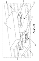
- the workpiece 901 can be lowered so that the balls 107, 207 and 307 come to rest within their respective sockets 102, 202 and 302, as seen in Fig. 12 .
- the rings 104 and 204 can move within the sockets 102 and 202 to adapt to any small variation in the relative positions of the attachment points 902 within their manufacturing tolerances.
- the balls 107, 207 and 307 can then be clamped to fix their positions and orientations by tightly screwing the external members 113, 213 and 313 of their clamping means onto the sockets 102, 202 and 302. Because of the alignment of the rings 104 and 204 with their corresponding balls 107 and 207, the internal stresses in the workpiece 901 between the attachment points 902 are minimised.
Landscapes
- Engineering & Computer Science (AREA)
- Mechanical Engineering (AREA)
- General Engineering & Computer Science (AREA)
- Jigs For Machine Tools (AREA)
- Electrical Discharge Machining, Electrochemical Machining, And Combined Machining (AREA)
- Load-Engaging Elements For Cranes (AREA)
Priority Applications (7)
| Application Number | Priority Date | Filing Date | Title |
|---|---|---|---|
| EP07112801A EP2017034A1 (de) | 2007-07-19 | 2007-07-19 | Verfahren, System und Vorrichtung zum Halten eines Werkstücks |
| US12/669,352 US8550442B2 (en) | 2007-07-19 | 2008-07-18 | Workpiece holding device, system and method |
| PCT/EP2008/059470 WO2009010586A1 (en) | 2007-07-19 | 2008-07-18 | Workpiece holding device, system and method |
| AT08786250T ATE507027T1 (de) | 2007-07-19 | 2008-07-18 | Werkstückhaltevorrichtung, -system und -verfahren |
| EP08786250A EP2185315B1 (de) | 2007-07-19 | 2008-07-18 | Werkstückhaltevorrichtung, -system und -verfahren |
| DE602008006567T DE602008006567D1 (de) | 2007-07-19 | 2008-07-18 | Werkstückhaltevorrichtung, -system und -verfahren |
| ES08786250T ES2364886T3 (es) | 2007-07-19 | 2008-07-18 | Dispositivo, sistema y método de sujeción de una pieza de trabajo. |
Applications Claiming Priority (1)
| Application Number | Priority Date | Filing Date | Title |
|---|---|---|---|
| EP07112801A EP2017034A1 (de) | 2007-07-19 | 2007-07-19 | Verfahren, System und Vorrichtung zum Halten eines Werkstücks |
Publications (1)
| Publication Number | Publication Date |
|---|---|
| EP2017034A1 true EP2017034A1 (de) | 2009-01-21 |
Family
ID=38581993
Family Applications (2)
| Application Number | Title | Priority Date | Filing Date |
|---|---|---|---|
| EP07112801A Withdrawn EP2017034A1 (de) | 2007-07-19 | 2007-07-19 | Verfahren, System und Vorrichtung zum Halten eines Werkstücks |
| EP08786250A Not-in-force EP2185315B1 (de) | 2007-07-19 | 2008-07-18 | Werkstückhaltevorrichtung, -system und -verfahren |
Family Applications After (1)
| Application Number | Title | Priority Date | Filing Date |
|---|---|---|---|
| EP08786250A Not-in-force EP2185315B1 (de) | 2007-07-19 | 2008-07-18 | Werkstückhaltevorrichtung, -system und -verfahren |
Country Status (6)
| Country | Link |
|---|---|
| US (1) | US8550442B2 (de) |
| EP (2) | EP2017034A1 (de) |
| AT (1) | ATE507027T1 (de) |
| DE (1) | DE602008006567D1 (de) |
| ES (1) | ES2364886T3 (de) |
| WO (1) | WO2009010586A1 (de) |
Cited By (3)
| Publication number | Priority date | Publication date | Assignee | Title |
|---|---|---|---|---|
| AT14628U1 (de) * | 2014-12-16 | 2016-02-15 | Supanz Vermietungs Kg | Spanneinrichtung |
| CN106426287A (zh) * | 2016-11-09 | 2017-02-22 | 北京工业大学 | 一种应用于工业机器人的柔性末端连接装置 |
| CN111716263A (zh) * | 2020-05-26 | 2020-09-29 | 苏州浪潮智能科技有限公司 | 一种用于带有riser的主板的测试支撑装置 |
Families Citing this family (21)
| Publication number | Priority date | Publication date | Assignee | Title |
|---|---|---|---|---|
| US9678803B2 (en) | 2007-06-22 | 2017-06-13 | Red Hat, Inc. | Migration of network entities to a cloud infrastructure |
| CN101543993B (zh) * | 2008-03-25 | 2012-03-28 | 鸿富锦精密工业(深圳)有限公司 | 机械手 |
| US8235367B2 (en) * | 2009-06-10 | 2012-08-07 | Seagate Technology Llc | Selectively positioning a workpiece |
| DE102011119392A1 (de) * | 2011-11-24 | 2013-05-29 | Knorr-Bremse Systeme für Nutzfahrzeuge GmbH | Justierbare Halterungsvorrichtung für Sensoren |
| CN202952084U (zh) * | 2012-08-03 | 2013-05-29 | 富鼎电子科技(嘉善)有限公司 | 定位结构及采用该定位结构的加工装置 |
| CN103659334A (zh) * | 2013-11-28 | 2014-03-26 | 无锡市航鹄科技有限公司 | 高效车外圆定位工装 |
| CN106314820B (zh) * | 2015-06-29 | 2021-05-07 | 中国商用飞机有限责任公司 | 插销式防逃逸工艺接头及其应用方法 |
| ITUA20162560A1 (it) * | 2016-04-13 | 2017-10-13 | Vitec Imaging Solutions S P A | Modulo orientabile per apparecchiature video-fotografiche |
| CN105880881B (zh) * | 2016-06-08 | 2018-04-24 | 昆山韦德智能装备科技有限公司 | 一种智能焊接机器人装置 |
| RU2733016C2 (ru) * | 2016-06-23 | 2020-09-28 | Хексагон Текнолоджи Ас | Система и способ поддержки сосуда под давлением |
| CN108344513B (zh) * | 2018-03-08 | 2023-08-01 | 辽宁艾科瑞焦化节能环保工程技术有限公司 | 具有瞄准与成像功能的焦炉鼻梁砖测温装置及其使用方法 |
| US11247307B2 (en) * | 2018-09-13 | 2022-02-15 | James A. Kollias | Modular, cam locked soft jaw for holding workpieces securely and accurately in a machine tool |
| EP3670068B1 (de) * | 2018-12-20 | 2023-06-07 | Fundación Tecnalia Research & Innovation | System zum tragen von werkstücken |
| GB2582820B (en) * | 2019-04-05 | 2023-06-28 | Videndum Plc | A head assembly for a tripod |
| US12397391B2 (en) * | 2021-06-19 | 2025-08-26 | Multiquip Inc. | Grinding head assembly and driver interface |
| US12030194B1 (en) * | 2021-09-01 | 2024-07-09 | Diamond Age 3D, Inc. | Six degrees of freedom anchoring device and method for robotic installation |
| CH719244A1 (de) * | 2021-12-13 | 2023-06-30 | Erowa Ag | Spanneinrichtung. |
| US20240051090A1 (en) * | 2022-08-15 | 2024-02-15 | Michael Brian Sargent | Repeatable Clamping Device |
| CN115502919A (zh) * | 2022-09-19 | 2022-12-23 | 中国工程物理研究院激光聚变研究中心 | 位姿调整机构及基于该调整机构的6自由度容错调节方法 |
| CN115753833B (zh) * | 2022-11-22 | 2025-06-24 | 南京海川电子有限公司 | 一种精密保护器焊点视觉检测装置 |
| AT527340A1 (de) | 2023-07-14 | 2025-01-15 | Gtech Automatisierungstechnik Gmbh | Auflagevorrichtung |
Citations (3)
| Publication number | Priority date | Publication date | Assignee | Title |
|---|---|---|---|---|
| GB1014809A (en) * | 1964-07-27 | 1965-12-31 | Wilton Corp | Adjustable work positioner |
| EP0461994A1 (de) * | 1990-06-15 | 1991-12-18 | NORELEM, Société Anonyme dite : | Vorrichtung zum Halten eines Werkstückes |
| US5466078A (en) * | 1989-07-07 | 1995-11-14 | Health Care Keyboard Company | Input keyboard apparatus for information processing and other keyboard devices |
Family Cites Families (4)
| Publication number | Priority date | Publication date | Assignee | Title |
|---|---|---|---|---|
| US5224692A (en) * | 1991-08-12 | 1993-07-06 | Anderson Donald W | Versatile wide opening vise |
| US5305992A (en) * | 1993-04-19 | 1994-04-26 | The Budd Company | Measuring fixture with gauge ball |
| US6305447B1 (en) * | 2000-08-28 | 2001-10-23 | Tony Rousseau | Base plate for mounting router in a support table |
| US7387284B2 (en) * | 2005-11-28 | 2008-06-17 | Ta Shuo Chang | Mechanism for fastening a pivotal support in any direction |
-
2007
- 2007-07-19 EP EP07112801A patent/EP2017034A1/de not_active Withdrawn
-
2008
- 2008-07-18 AT AT08786250T patent/ATE507027T1/de not_active IP Right Cessation
- 2008-07-18 DE DE602008006567T patent/DE602008006567D1/de active Active
- 2008-07-18 WO PCT/EP2008/059470 patent/WO2009010586A1/en not_active Ceased
- 2008-07-18 EP EP08786250A patent/EP2185315B1/de not_active Not-in-force
- 2008-07-18 US US12/669,352 patent/US8550442B2/en not_active Expired - Fee Related
- 2008-07-18 ES ES08786250T patent/ES2364886T3/es active Active
Patent Citations (3)
| Publication number | Priority date | Publication date | Assignee | Title |
|---|---|---|---|---|
| GB1014809A (en) * | 1964-07-27 | 1965-12-31 | Wilton Corp | Adjustable work positioner |
| US5466078A (en) * | 1989-07-07 | 1995-11-14 | Health Care Keyboard Company | Input keyboard apparatus for information processing and other keyboard devices |
| EP0461994A1 (de) * | 1990-06-15 | 1991-12-18 | NORELEM, Société Anonyme dite : | Vorrichtung zum Halten eines Werkstückes |
Cited By (4)
| Publication number | Priority date | Publication date | Assignee | Title |
|---|---|---|---|---|
| AT14628U1 (de) * | 2014-12-16 | 2016-02-15 | Supanz Vermietungs Kg | Spanneinrichtung |
| CN106426287A (zh) * | 2016-11-09 | 2017-02-22 | 北京工业大学 | 一种应用于工业机器人的柔性末端连接装置 |
| CN111716263A (zh) * | 2020-05-26 | 2020-09-29 | 苏州浪潮智能科技有限公司 | 一种用于带有riser的主板的测试支撑装置 |
| CN111716263B (zh) * | 2020-05-26 | 2022-05-10 | 苏州浪潮智能科技有限公司 | 一种用于带有riser的主板的测试支撑装置 |
Also Published As
| Publication number | Publication date |
|---|---|
| EP2185315B1 (de) | 2011-04-27 |
| US20100252978A1 (en) | 2010-10-07 |
| US8550442B2 (en) | 2013-10-08 |
| WO2009010586A1 (en) | 2009-01-22 |
| DE602008006567D1 (de) | 2011-06-09 |
| ES2364886T3 (es) | 2011-09-16 |
| EP2185315A1 (de) | 2010-05-19 |
| ATE507027T1 (de) | 2011-05-15 |
Similar Documents
| Publication | Publication Date | Title |
|---|---|---|
| EP2185315B1 (de) | Werkstückhaltevorrichtung, -system und -verfahren | |
| US8708323B2 (en) | Mounting system | |
| DE102014112843B4 (de) | Nullpunkt-Spannsystem | |
| CN100431783C (zh) | 工件夹紧装置 | |
| US20090194922A1 (en) | Reconfigurable end-of-arm tool for robotic arm | |
| US8714860B2 (en) | Mounting fixture including an articulation joint | |
| CN109015019B (zh) | 工件固定装置和用于给工件固定装置配备工件的方法 | |
| CA2373085C (en) | Quickly adjustable multiple clamping system | |
| US6286823B1 (en) | Workpiece indexing and clamping system | |
| DE102014112845A1 (de) | Spannbacken-Schnellverschluss, insbesondere eines Nullpunkt-Spannsystems | |
| US5624106A (en) | Gripping device | |
| US10456827B2 (en) | Interchangeable die transfer station, joining tool system and joining method | |
| EP1929162B1 (de) | Klemmteil und haltevorrichtung mit einem klemmteil dieser art | |
| DE102014001963B4 (de) | Spannvorrichtung zum reproduzierbar, lagengenauen Festspannen von Werkstücken | |
| US11065730B2 (en) | Work piece mounting system | |
| US20100316439A1 (en) | Mounting system | |
| US20150167731A1 (en) | Adjustable Joints | |
| US4155542A (en) | Device for holding workpieces | |
| US5199725A (en) | Adjustable top jaw | |
| EP1620227A1 (de) | Spannysytem mit adapterteil | |
| CN209850377U (zh) | 一种万向锁紧工装 | |
| US20230009066A1 (en) | Clamp for retaining a workpiece | |
| US5155898A (en) | Rotary chuck soft jaws | |
| DE10305601B4 (de) | Werkzeugadapter | |
| EP3366417B1 (de) | Spannbolzen eines nullpunktspannsystems |
Legal Events
| Date | Code | Title | Description |
|---|---|---|---|
| PUAI | Public reference made under article 153(3) epc to a published international application that has entered the european phase |
Free format text: ORIGINAL CODE: 0009012 |
|
| AK | Designated contracting states |
Kind code of ref document: A1 Designated state(s): AT BE BG CH CY CZ DE DK EE ES FI FR GB GR HU IE IS IT LI LT LU LV MC MT NL PL PT RO SE SI SK TR |
|
| AX | Request for extension of the european patent |
Extension state: AL BA HR MK RS |
|
| AKX | Designation fees paid | ||
| REG | Reference to a national code |
Ref country code: DE Ref legal event code: 8566 |
|
| STAA | Information on the status of an ep patent application or granted ep patent |
Free format text: STATUS: THE APPLICATION IS DEEMED TO BE WITHDRAWN |
|
| 18D | Application deemed to be withdrawn |
Effective date: 20090722 |