EP2017045A2 - Kettensäge - Google Patents
Kettensäge Download PDFInfo
- Publication number
- EP2017045A2 EP2017045A2 EP08252350A EP08252350A EP2017045A2 EP 2017045 A2 EP2017045 A2 EP 2017045A2 EP 08252350 A EP08252350 A EP 08252350A EP 08252350 A EP08252350 A EP 08252350A EP 2017045 A2 EP2017045 A2 EP 2017045A2
- Authority
- EP
- European Patent Office
- Prior art keywords
- shaft
- driven gear
- drive
- chainsaw
- final drive
- Prior art date
- Legal status (The legal status is an assumption and is not a legal conclusion. Google has not performed a legal analysis and makes no representation as to the accuracy of the status listed.)
- Withdrawn
Links
Images


Classifications
-
- B—PERFORMING OPERATIONS; TRANSPORTING
- B27—WORKING OR PRESERVING WOOD OR SIMILAR MATERIAL; NAILING OR STAPLING MACHINES IN GENERAL
- B27B—SAWS FOR WOOD OR SIMILAR MATERIAL; COMPONENTS OR ACCESSORIES THEREFOR
- B27B17/00—Chain saws; Equipment therefor
- B27B17/08—Drives or gearings; Devices for swivelling or tilting the chain saw
- B27B17/10—Transmission clutches specially designed for chain saws
-
- B—PERFORMING OPERATIONS; TRANSPORTING
- B27—WORKING OR PRESERVING WOOD OR SIMILAR MATERIAL; NAILING OR STAPLING MACHINES IN GENERAL
- B27B—SAWS FOR WOOD OR SIMILAR MATERIAL; COMPONENTS OR ACCESSORIES THEREFOR
- B27B17/00—Chain saws; Equipment therefor
- B27B17/08—Drives or gearings; Devices for swivelling or tilting the chain saw
- B27B17/083—Devices for arresting movement of the saw chain
-
- F—MECHANICAL ENGINEERING; LIGHTING; HEATING; WEAPONS; BLASTING
- F16—ENGINEERING ELEMENTS AND UNITS; GENERAL MEASURES FOR PRODUCING AND MAINTAINING EFFECTIVE FUNCTIONING OF MACHINES OR INSTALLATIONS; THERMAL INSULATION IN GENERAL
- F16D—COUPLINGS FOR TRANSMITTING ROTATION; CLUTCHES; BRAKES
- F16D41/00—Freewheels or freewheel clutches
- F16D41/20—Freewheels or freewheel clutches with expandable or contractable clamping ring or band
- F16D41/206—Freewheels or freewheel clutches with expandable or contractable clamping ring or band having axially adjacent coils, e.g. helical wrap-springs
Definitions
- This invention relates to a power-operated tool, and in particular to a portable, power-operated chainsaw.
- a known chainsaw 1 (see Figure 1 ) includes a chain drive sprocket 2 which drivably engages a chain 3 of the chainsaw, the chain drive sprocket being carried by a final drive shaft 4.
- the final drive shaft 4 is driven by an output shaft 5 of a drive motor 6 via intermeshing drive and driven gear wheels 7 and 8 provided respectively on the motor output shaft and on the final drive shaft.
- This chainsaw 1 has a brake and clutch mechanism constituted by a wrap spring clutch 9 which surrounds the final drive shaft 4 and a stub shaft (not shown) formed integrally with the driven gear 8 adjacent to the chain drive sprocket 2.
- the uncoiled spring 9 is thereby disengaged from the stub shaft of the driven gear 8 so that the gears 7 and 8 continue to rotate as the motor 6 decelerates, but continues to engage the final drive shaft 4, thereby to apply a braking force to that shaft, and hence to the chain drive sprocket 2 and the chain 3.
- a disadvantage of this known chainsaw 1 is that, because the wrap-spring clutch 9 is positioned on the opposite side of the driven gear 8 to the drive motor 6, the housing which accommodates the driven gear and the chain drive sprocket 2 has a substantial width, which results in the chainsaw being bulky and costly to produce.
- the present invention provides a chainsaw comprising a drive motor in drivable engagement with a chain via a motor output shaft and a chain drive sprocket associated with a final drive shaft, the motor output shaft being in drivable engagement with the final drive shaft via intermeshing drive and driven gear wheels associated respectively with the motor output shaft and the final drive shaft, wherein the driven gear wheel is provided with an axial stub shaft extending away from the drive sprocket, and a wrap-spring clutch is engageable with the stub shaft and the final drive shaft to provide selective drive between the stub shaft and the final drive shaft.
- the chainsaw further comprises a fan associated with the motor output shaft.
- the wrap-spring clutch may be positioned adjacent to the fan.
- the stub shaft is made of steel and the driven gear wheel is made of a plastics material, the stub shaft and the driven gear wheel being fixed together by moulding the driven gear over the stub shaft.
- the stub shaft is provided with features through which the plastics material of the driven gear flows, thereby to fix the stub shaft and the driven gear securely together.
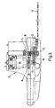
- Figure 2 shows a chainsaw 11 having a chain drive sprocket 12 which drivably engages a chain 13 of the chainsaw, the chain drive sprocket being carried by a final drive shaft 14.
- the final draft shaft 14 is driven by an output shaft 15 of a drive motor 16 via intermeshing drive and driven gear wheels 17 and 18 provided respectively on the motor output shaft and on the final drive shaft.
- the chainsaw 11 has a brake and clutch mechanism constituted by a wrap-spring clutch 19 which surrounds the final drive shaft 14 and a stub shaft 18a (see Figure 3 ) fixed to the driven gear 18 adjacent to a fan 20 provided on the output shaft 15 of the motor 16.
- the stub shaft 18a is made of steel, and the driven gear 18 is made of a plastics material such as PA6 nylon, these two parts being fixed together by moulding the driven gear over the stub shaft.
- the stub shaft 18a has features (not shown), through which the plastics material flows, thereby to fix the two parts securely together.
- the uncoiled spring 19 is thereby disengaged from the stub shaft 18a of the driven gear 18 so that the gears 17 and 18 continue to rotate as the motor 16 decelerates, but continues to engage the final drive shaft 14, thereby to apply a braking force to that shaft, and hence to the chain drive sprocket 12 and the chain 13.
- the overall width of the chainsaw is reduced by approximately 32 mm, thereby producing a more compact machine. Not only is this chainsaw more compact than known chainsaws, but it is also easier to handle as the chainsaw itself is positioned nearer the centre of gravity of the machine.
Landscapes
- Engineering & Computer Science (AREA)
- Life Sciences & Earth Sciences (AREA)
- Mechanical Engineering (AREA)
- General Engineering & Computer Science (AREA)
- Wood Science & Technology (AREA)
- Forests & Forestry (AREA)
- Devices For Conveying Motion By Means Of Endless Flexible Members (AREA)
- Gears, Cams (AREA)
- Transmission Devices (AREA)
- Sawing (AREA)
Applications Claiming Priority (1)
| Application Number | Priority Date | Filing Date | Title |
|---|---|---|---|
| GB0714248A GB2451139A (en) | 2007-07-20 | 2007-07-20 | Wrap spring clutch and fan arrangement in a chainsaw |
Publications (2)
| Publication Number | Publication Date |
|---|---|
| EP2017045A2 true EP2017045A2 (de) | 2009-01-21 |
| EP2017045A3 EP2017045A3 (de) | 2010-12-29 |
Family
ID=38476749
Family Applications (1)
| Application Number | Title | Priority Date | Filing Date |
|---|---|---|---|
| EP08252350A Withdrawn EP2017045A3 (de) | 2007-07-20 | 2008-07-10 | Kettensäge |
Country Status (2)
| Country | Link |
|---|---|
| EP (1) | EP2017045A3 (de) |
| GB (1) | GB2451139A (de) |
Cited By (2)
| Publication number | Priority date | Publication date | Assignee | Title |
|---|---|---|---|---|
| US11472058B2 (en) | 2019-11-25 | 2022-10-18 | Milwaukee Electric Tool Corporation | Powered handheld cutting tool |
| USD1051691S1 (en) * | 2024-02-27 | 2024-11-19 | Minli Liao | Chainsaw |
Families Citing this family (1)
| Publication number | Priority date | Publication date | Assignee | Title |
|---|---|---|---|---|
| DE102012015814B4 (de) * | 2012-08-10 | 2014-12-11 | Mogatec Moderne Gartentechnik Gmbh | Motorkettensäge mit einer Schlingfederkupplung und einer Reibungsbremse |
Family Cites Families (8)
| Publication number | Priority date | Publication date | Assignee | Title |
|---|---|---|---|---|
| US2643749A (en) * | 1948-12-31 | 1953-06-30 | Marquette Metal Products Co | Spring type clutch |
| US2915158A (en) * | 1954-03-12 | 1959-12-01 | Maytag Co | Control means for spring clutch drives |
| US3142196A (en) * | 1961-05-26 | 1964-07-28 | Remington Arms Co Inc | Transmission for a chain saw |
| US3857179A (en) * | 1974-04-22 | 1974-12-31 | Desa Industries | Chain saw |
| EP0072610A3 (de) * | 1981-06-22 | 1984-05-30 | Skil Corporation | Integral Abbrems- und Auskuppelgetriebe |
| DE3607376A1 (de) * | 1986-03-06 | 1987-09-10 | Metabowerke Kg | Tragbare motorkettensaege mit einer reibungsbremse zum abbremsen der saegekette |
| DE19812860A1 (de) * | 1998-03-24 | 1999-09-30 | Bosch Gmbh Robert | Kettensäge |
| GB0515884D0 (en) * | 2005-08-02 | 2005-09-07 | Bosch Gmbh Robert | Improvements in or relating to chainsaws |
-
2007
- 2007-07-20 GB GB0714248A patent/GB2451139A/en not_active Withdrawn
-
2008
- 2008-07-10 EP EP08252350A patent/EP2017045A3/de not_active Withdrawn
Cited By (4)
| Publication number | Priority date | Publication date | Assignee | Title |
|---|---|---|---|---|
| US11472058B2 (en) | 2019-11-25 | 2022-10-18 | Milwaukee Electric Tool Corporation | Powered handheld cutting tool |
| US11872718B2 (en) | 2019-11-25 | 2024-01-16 | Milwaukee Electric Tool Corporation | Powered handheld cutting tool |
| US12269187B2 (en) | 2019-11-25 | 2025-04-08 | Milwaukee Electric Tool Corporation | Powered handheld cutting tool |
| USD1051691S1 (en) * | 2024-02-27 | 2024-11-19 | Minli Liao | Chainsaw |
Also Published As
| Publication number | Publication date |
|---|---|
| GB2451139A (en) | 2009-01-21 |
| EP2017045A3 (de) | 2010-12-29 |
| GB0714248D0 (en) | 2007-08-29 |
Similar Documents
| Publication | Publication Date | Title |
|---|---|---|
| US11701789B2 (en) | Hand-held knockout punch driver | |
| EP3338530B1 (de) | Antriebssystem für gartenwerkzeug mit automatischer gehfunktion | |
| CN203156866U (zh) | 链锯 | |
| US20080287247A1 (en) | Planetary Gear Set Centering Ring | |
| US20130192432A1 (en) | Drive train for a hedge trimmer, a hedge trimmer and a method of controlling a hedge trimmer | |
| US8011445B2 (en) | Portable power tool, in particular a drilling hammer and/or impact hammer | |
| GB2451139A (en) | Wrap spring clutch and fan arrangement in a chainsaw | |
| WO2007147157A3 (en) | Battery-operated pruning device | |
| KR101568102B1 (ko) | 끼임 방지용 체인 톱 | |
| EP2318169B1 (de) | Kettenloses antriebssystem für eine bandsäge | |
| CN201128028Y (zh) | 一种手持式汽油动力圆锯机 | |
| JP2005328847A (ja) | 動力工具用ブレーキシステム | |
| JP2002219669A (ja) | ドリル−チゼルハンマ | |
| CN101480938B (zh) | 智能三点式安全带 | |
| FR2854090B1 (fr) | Dispositif de securite pour machines electrique en particulier tronconneuse | |
| CN201082554Y (zh) | 链锯刹车装置 | |
| US7594856B2 (en) | Overload clutch device, clutch disk, and driving toothed wheel | |
| AU2005229663B2 (en) | A Conveyor Drive Including a Fluid Coupling and a Set-up Gearbox | |
| KR101237705B1 (ko) | 목재 파쇄기 | |
| JP2011183479A (ja) | ボルト締付機 | |
| PL2172270T3 (pl) | Zastosowanie hamulca w urządzeniu napędowym rozdrabniarki | |
| US20050139445A1 (en) | Wedge clutch assembly | |
| CA2497190C (en) | Wedge clutch assembly | |
| WO2024162879A1 (en) | A handheld battery powered chainsaw with a centrifugal clutch | |
| WO2007144860A2 (en) | Bicycle multi spindle |
Legal Events
| Date | Code | Title | Description |
|---|---|---|---|
| PUAI | Public reference made under article 153(3) epc to a published international application that has entered the european phase |
Free format text: ORIGINAL CODE: 0009012 |
|
| AK | Designated contracting states |
Kind code of ref document: A2 Designated state(s): AT BE BG CH CY CZ DE DK EE ES FI FR GB GR HR HU IE IS IT LI LT LU LV MC MT NL NO PL PT RO SE SI SK TR |
|
| AX | Request for extension of the european patent |
Extension state: AL BA MK RS |
|
| PUAL | Search report despatched |
Free format text: ORIGINAL CODE: 0009013 |
|
| AK | Designated contracting states |
Kind code of ref document: A3 Designated state(s): AT BE BG CH CY CZ DE DK EE ES FI FR GB GR HR HU IE IS IT LI LT LU LV MC MT NL NO PL PT RO SE SI SK TR |
|
| AX | Request for extension of the european patent |
Extension state: AL BA MK RS |
|
| AKY | No designation fees paid | ||
| REG | Reference to a national code |
Ref country code: DE Ref legal event code: R108 |
|
| REG | Reference to a national code |
Ref country code: DE Ref legal event code: R108 Effective date: 20110907 |
|
| STAA | Information on the status of an ep patent application or granted ep patent |
Free format text: STATUS: THE APPLICATION IS DEEMED TO BE WITHDRAWN |
|
| 18D | Application deemed to be withdrawn |
Effective date: 20110630 |