EP2017047B2 - Verfahren zur Auswahl von Abschalprofilen zur Herstellung einer Schalung für ein Betonfertigbauelement und entsprechende Schalung. - Google Patents
Verfahren zur Auswahl von Abschalprofilen zur Herstellung einer Schalung für ein Betonfertigbauelement und entsprechende Schalung. Download PDFInfo
- Publication number
- EP2017047B2 EP2017047B2 EP08012905.9A EP08012905A EP2017047B2 EP 2017047 B2 EP2017047 B2 EP 2017047B2 EP 08012905 A EP08012905 A EP 08012905A EP 2017047 B2 EP2017047 B2 EP 2017047B2
- Authority
- EP
- European Patent Office
- Prior art keywords
- formwork
- profiles
- pallet
- station
- manufactured
- Prior art date
- Legal status (The legal status is an assumption and is not a legal conclusion. Google has not performed a legal analysis and makes no representation as to the accuracy of the status listed.)
- Active
Links
Images
Classifications
-
- B—PERFORMING OPERATIONS; TRANSPORTING
- B28—WORKING CEMENT, CLAY, OR STONE
- B28B—SHAPING CLAY OR OTHER CERAMIC COMPOSITIONS; SHAPING SLAG; SHAPING MIXTURES CONTAINING CEMENTITIOUS MATERIAL, e.g. PLASTER
- B28B15/00—General arrangement or layout of plant ; Industrial outlines or plant installations
-
- B—PERFORMING OPERATIONS; TRANSPORTING
- B28—WORKING CEMENT, CLAY, OR STONE
- B28B—SHAPING CLAY OR OTHER CERAMIC COMPOSITIONS; SHAPING SLAG; SHAPING MIXTURES CONTAINING CEMENTITIOUS MATERIAL, e.g. PLASTER
- B28B17/00—Details of, or accessories for, apparatus for shaping the material; Auxiliary measures taken in connection with such shaping
- B28B17/0063—Control arrangements
- B28B17/0081—Process control
-
- B—PERFORMING OPERATIONS; TRANSPORTING
- B28—WORKING CEMENT, CLAY, OR STONE
- B28B—SHAPING CLAY OR OTHER CERAMIC COMPOSITIONS; SHAPING SLAG; SHAPING MIXTURES CONTAINING CEMENTITIOUS MATERIAL, e.g. PLASTER
- B28B5/00—Producing shaped articles from the material in moulds or on moulding surfaces, carried or formed by, in or on conveyors irrespective of the manner of shaping
- B28B5/04—Producing shaped articles from the material in moulds or on moulding surfaces, carried or formed by, in or on conveyors irrespective of the manner of shaping in moulds moved in succession past one or more shaping stations
-
- B—PERFORMING OPERATIONS; TRANSPORTING
- B28—WORKING CEMENT, CLAY, OR STONE
- B28B—SHAPING CLAY OR OTHER CERAMIC COMPOSITIONS; SHAPING SLAG; SHAPING MIXTURES CONTAINING CEMENTITIOUS MATERIAL, e.g. PLASTER
- B28B7/00—Moulds; Cores; Mandrels
- B28B7/0029—Moulds or moulding surfaces not covered by B28B7/0058 - B28B7/36 and B28B7/40 - B28B7/465, e.g. moulds assembled from several parts
- B28B7/0032—Moulding tables or similar mainly horizontal moulding surfaces
-
- B—PERFORMING OPERATIONS; TRANSPORTING
- B28—WORKING CEMENT, CLAY, OR STONE
- B28B—SHAPING CLAY OR OTHER CERAMIC COMPOSITIONS; SHAPING SLAG; SHAPING MIXTURES CONTAINING CEMENTITIOUS MATERIAL, e.g. PLASTER
- B28B7/00—Moulds; Cores; Mandrels
- B28B7/02—Moulds with adjustable parts specially for modifying at will the dimensions or form of the moulded article
Definitions
- the invention relates to a method for producing at least one formwork for a polygonal, in particular rectangular, prefabricated concrete element on a pallet form a pallet circulation system of several Abschalprofilen for producing the at least one formwork with a substantially closed inner peripheral edge for a polygonal, in particular rectangular precast concrete element on a Pallet form are arranged, wherein only substantially equally trained Abschalprofile with standard lengths are used to form the substantially closed inner peripheral edge and the selection of Abschalprofile to be positioned according to the set values of their length, which is determined in particular on the basis of a geometric data set for the finished concrete element to be manufactured ,
- these mating elements In addition to the enormous amount of time required for the manual production and positioning of the fitting elements, these mating elements also require a manual removal of the mating elements when demoulding the precast concrete element, which results in an enormous time delay, which is particularly disadvantageous when the precast concrete elements manufactured in a production line become.
- the DE 103 04 622 B3 and the DE 101 16 230 C1 each show a method for erecting a formwork for precast concrete components, in which Abschalprofile are arranged one behind the other, and a formwork for a manufactured on a pallet form precast concrete element.
- Abschalprofile are arranged one behind the other
- a formwork for a manufactured on a pallet form precast concrete element is disclosed in each case by means of which the formwork elements can be arranged one behind the other without a gap.
- the US 3,730,657 A shows a device for pressing not yet cured concrete, which also serves as formwork.
- the EP 1 273 407 A1 shows a Magnetsetzroboter for spatially positioned settling and / or receiving magnets for the arrangement of formwork in the manufacture of precast concrete components, wherein the Magnetsetzroboter can simultaneously accommodate a plurality of magnets.
- the invention has the object to provide a method for producing a formwork of Abschalprofilen according to the teaching of claim 1, which allows avoiding the disadvantages described above, a quick shelling and Entschalen and in particular for use in automated production lines is suitable.
- the selection of the Abschalprofle takes place such that the sum of the longitudinal extent of the at least two sequentially arranged Abschalprofrate is smaller than the length of the side of the formwork to be produced.
- the invention provides that the sum of the longitudinal extent of the Abschalprofile to be arranged behind the other at most by the value f is smaller than the length of the side of the formwork to be produced.
- the invention further relates to a formwork for a manufactured on a pallet form, in particular rectangular concrete prefabricated element according to the teaching of claim 5, whose substantially closed inner peripheral edge of several elongated Abschalprofilen is limited, wherein at least one side of the inner peripheral edge of the formwork of at least two substantially equal trained Abschalprofilen with standard lengths is formed, which are arranged one behind the other in the longitudinal direction.
- Abschalprofilen In known formwork as many sides of the finished concrete element to be manufactured are formed by Abschalprofilen standardized length. Since the standardized lengths of Abschalprofile in the fewest cases correspond to the side lengths of the concrete precast element to be produced, remaining gaps in the peripheral edge of the shells are achieved by means of so-called fitting elements according to the prior art filled. These mating elements can be made of styrofoam or wooden parts, for example, and are usually shortened and fitted manually to the required length during the production of the formwork.
- one side of the formwork is formed by at least two series-laid shuttering profiles of standardized length, it is possible to dispense with the use of fitting elements as a whole, which results in an enormous saving of time.
- An embodiment of the invention further relates to the use of a plant for the production of precast concrete elements with a production line, in which the production of the components takes place on pallet forms, which successively at least one de-scaling station, a cleaning station, a particular automatic formwork station, a concreting station, a reinforcement station and a curing chamber a production line undergo in a method according to an embodiment.
- Such systems are used to produce flat concrete elements, in particular ceiling and wall elements.
- the production of concrete elements takes place on pallet forms, also called production pallets, which successively pass through several stations of a production line.
- the precast concrete element is de-energized and the Sheathing profiles removed from the pallet form.
- the cleaning of the pallet forms before they are equipped at the Schalstation with new formwork.
- the pallet shape is fed to the curing chamber, in which the setting of the concrete takes place.
- the arrangement of buffer stations at which the pallet form is taken out of circulation is necessary due to the different duration of the work cycles at the individual stations, that is, after stations with a shorter working cycle, such as the Entschaluhgsstation, Buffer zones are provided in which the pallet shapes can be parked until the subsequent station in the production line is free.
- This object is achieved by synchronizing the feeding of the pallet shapes from the de-scaling station to the curing chamber. Characterized in that the feed takes place according to the invention at the same time, can be dispensed with the arrangement of buffer stations entirely and production bottlenecks can be avoided.
- a further embodiment of the invention provides that in the course of the production line, one or more blind station (s) on which (no) operations take place are arranged, whereby attempts of the applicant have shown that an arrangement of a blind station between the Cleaning and formwork station and / or the formwork and concreting station is particularly advantageous for a smooth passage of the pallet shape through the production line.
- the blind stations serve to bridge longer distances between two processing stations. This is necessary because, as a result of the synchronous feed of all pallet shapes, a longer transport time between two stations due to a longer distance would shorten the time available for coping with the subsequent work cycle.
- the feed of the pallet shapes takes place synchronously at all stations of the production line, wherein it has turned out to be advantageous if the pallet forms pass through the production line all around.
- One aspect of the invention is therefore to synchronously, i.e. at all stages of the production line, the pallet molds at least from the de-scaling station to the curing chamber. to move at the same time.
- the clock of the synchronous shift will depend on the time of the power strokes at the individual stations and the transport time between the individual stations of the production line.
- the synchronous feed of the pallet forms takes place at regular time intervals, wherein the clock of the synchronous shift in dependence of a predetermined maximum time per power stroke at the individual stations of the production line and the transport time of the pallet forms between the individual stations of the production line is fixed.
- the timing of the synchronous shift which corresponds to the time between the individual feeds, is composed of the time of the power strokes and the transport time between the individual stations.
- the maximum time per power cycle at the individual stations of the production line is less than 6 minutes, preferably less than 4.5 minutes, with a particularly high utilization of Production line can be achieved when the maximum time is less than 4 minutes, preferably about 3.5 minutes.
- the cycle time of the synchronous shift can also shorten, which is provided according to a further embodiment of the invention that the cycle time of the synchronous shift between , 5 and 5.5 minutes, preferably about 4.5 minutes.
- Another embodiment of the invention provides that the synchronous feed of the pallet forms takes place at irregular time intervals, wherein the triggering of the synchronous shift takes place in dependence on the time of the longest working cycle of the individual stations of the production line.
- this embodiment is based on the time required for the power stroke at the slowest station. In contrast to the above-described embodiment, however, no maximum time is determined or predetermined for this time-consuming station, but takes place, the synchronous feed the pallet shapes after completion of the power stroke at the slowest station.
- the synchronization shift can be triggered automatically, preferably by means of a system control, or manually.
- the production of precast concrete element follows a completely new logic. While according to the state of the art as many precast concrete elements as possible have been produced on a production pallet, according to the invention only one precast concrete element per pallet form is produced. The poorer utilization of the individual pallet shapes brings with it the advantage of a fixed maximum working time per working cycle, which allows a consistent automation of the production line, so that ultimately the process can produce at least as many prefabricated concrete elements in the same time as with the conventional methods.
- the method according to the invention allows a tremendous reduction in personnel, which considerably increases the overall costs can be reduced.
- the maximum time per stroke allows a predictable turnaround time for a pallet shape through the production line, thereby avoiding production bottlenecks.
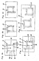
- Fig. 1 illustrated embodiment of a formwork 11 according to the invention three sides of the peripheral edge U a of Abschalprofilen 10 are formed with a standardized length.
- the fourth side of the formwork 11 with the side length L is in contrast to the embodiments according to Fig. 5a to 5c not formed by a projecting Abschalprofil 10 but rather by two set in series Abschalprofilen 10.
- a corresponding grid of different standard lengths for formwork profiles 10 almost all required side lengths L of a precast concrete element to be produced can be switched exclusively with shuttering profiles 10 of standardized length using this method. It play smaller distances between the series Shuttering profiles 10 no major role, however, the distance between the individual Abschalprofilen should not be greater than 1.5 cm to avoid spillage of the concrete.
- Fig. 2a to 2c are further embodiments of formwork 11, which are arranged on a pallet 21, shown.
- at least three of the formwork 11 forming Abschalprofile 10 project beyond the outer peripheral edge U a , in each case to the section A.
- the outer peripheral edge U a is defined by the Abschal vom 24 opposite longitudinal sides of Abschalprofile 10 and is the inner peripheral edge U l geometrically similar.
- the peripheral edge of the formwork 11 is formed by the Abschalprofilen 10, the Abschalvid 24 of Abschalprofile 10 forming the inner peripheral edge U l , while the Abschalvid 24 opposite sides of the Abschalprofile 10 are part of the outer peripheral edge U A.
- Fig. 2a stand all Abschalprofile 10 over the outer peripheral edge U A , while in the Fig. 2b and 2c only three Abschalprofile 10 protrude beyond the outer peripheral edge U A.
- Abschalprofile 10 The advantage of this arrangement of Abschalprofile 10 is that it can be dispensed with the use of fitting elements entirely, since the inner peripheral edge U l is limited to the whole of Abschalprofilen 10 standardized length.
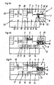
- Plant 1 shown comprises several stations, which are arranged such that the pallet molds 21, on which the precast concrete elements are produced, these stations in the sense of a production line in particular circulating through.
- This production line comprises a de-scaling station 2, in the region of which a demolition cross-piece 3 is arranged. Subsequent to the de-scaling station 2, a shuttering removal station 4 follows, in which the shuttering profiles 10 are removed from the pallet mold 21. This is followed by the cleaning station 6, which is associated with a cleaning and ⁇ lungsvorraum 5.
- the pallet molds 21 are conveyed to the formwork station 7.
- the shells of concrete precast elements by means of a formwork robot 8, which fetches the Abschalprofile 10 from the formwork bearing 9 and positioned on the pallet mold 21 located in the formwork station 7.
- the Abschalprofile 10 go through after removal of the pallet mold 21 in the formwork removal station 4, a transport and cleaning line 22 before being deposited in the formwork bearing 9.
- the formwork station 7 is followed by a blind station 12, at which no work is carried out.
- the concreting station 14 which is assigned to the concreting device 13, by means of which the concrete is introduced into the formwork 11.
- the concreting station 14 follows again a blind station 12 and thereupon the reinforcement station 15, in which by means of a positioning device 16, the prepared in the reinforcement preparation station 18 reinforcements are introduced into the already concrete, but not yet set concrete precast element.
- the recovery station 15 is followed by the pick-up station 17 and possibly another blind station 12.
- the pallet molds 21 are picked up by the picking station 17 or the subsequent blind station 12 and brought into the curing chamber 20, where the precast concrete element cures under supply of hot air. After setting of the concrete, the pallet mold 21 is transferred from the curing chamber 20 in the de-scaling station 2 and there begins a new round through the production line.
- Fig. 4b the transport routes between the individual stations of the production line are shown in a synchronous shift.
- the pallet molds 21 are moved within a minute from one station to the next, wherein the displacement takes place synchronously.
- Fig. 4c are the individual work processes, which must be performed during a power stroke whose maximum production time is set in the illustrated embodiment with 3.5 minutes.
- the shuttering profiles are removed on the shuttering removal station 4
- the pallet molds 21 are cleaned in the cleaning station 6
- the formwork 11 is produced on the formwork station 7 by the shuttering profiles 10
- concreting the Prefabricated concrete element takes place in the concreting station 14 wherein any reworking can be performed on the dummy station 12, on the rebar station 15, the reinforcements introduced while on the pickup 17 any special reinforcements can be introduced.
- the timing of the synchronous shift is composed of the maximum manufacturing time of 3.5 minutes and the transport time of 1 minute, i. the pallet molds 21 are moved every 4.5 minutes between the synchronously connected stations of the production line.
- the pallet molds 21 used in this embodiment are about 8 m long and 3 m wide, with about 88 pallets in a layer through the production line.
- a pallet occupancy of 11.25 m 2 which corresponds to a precast concrete element with a length of 4.5 m and a width of 2.5 m
- the plant 1 according to the invention can produce approximately 1.m 2 per shift with a duration of 8 working hours be achieved.
- the effective production time during one shift is 7 hours, while the cleaning time takes 1 hour.
- the number of personnel required for the monitoring of the plant can be reduced to up to 3 persons, while in plants according to the prior art, in which the feed of the pallet forms was not synchronized, sometimes up to 20 people were necessary ,
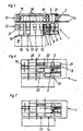
- FIG. 5 to 7 shown further embodiments of inventive systems 1 differ from the embodiment according to Fig. 4a to 4c only by the local arrangement of the individual stations of the production line, wherein in the embodiment according to Fig. 5 the stacking device 19 is formed by a stacker crane.
- FIG. 6 illustrated embodiment shows a system 1, with the addition of element ceilings and double walls can be made.
- a dummy station 12 is arranged after the concreting station 14, which is associated with a turning device 23 with a turning frame and suction cups.
- the operation of such Wenderahmen is known per se, which is why a description is omitted here.
- FIG. 7 illustrated embodiment differs from the in Fig. 3 shown example only in that just no such turning device 23 is provided, ie the system according to Fig. 7 serves for the production of flat element ceilings.
Landscapes
- Engineering & Computer Science (AREA)
- Chemical & Material Sciences (AREA)
- Ceramic Engineering (AREA)
- Mechanical Engineering (AREA)
- Manufacturing & Machinery (AREA)
- Automation & Control Theory (AREA)
- Devices For Post-Treatments, Processing, Supply, Discharge, And Other Processes (AREA)
- Moulds, Cores, Or Mandrels (AREA)
Applications Claiming Priority (1)
| Application Number | Priority Date | Filing Date | Title |
|---|---|---|---|
| AT11202007 | 2007-07-17 |
Publications (4)
| Publication Number | Publication Date |
|---|---|
| EP2017047A2 EP2017047A2 (de) | 2009-01-21 |
| EP2017047A3 EP2017047A3 (de) | 2011-02-16 |
| EP2017047B1 EP2017047B1 (de) | 2013-03-06 |
| EP2017047B2 true EP2017047B2 (de) | 2017-09-27 |
Family
ID=39874142
Family Applications (1)
| Application Number | Title | Priority Date | Filing Date |
|---|---|---|---|
| EP08012905.9A Active EP2017047B2 (de) | 2007-07-17 | 2008-07-17 | Verfahren zur Auswahl von Abschalprofilen zur Herstellung einer Schalung für ein Betonfertigbauelement und entsprechende Schalung. |
Country Status (3)
| Country | Link |
|---|---|
| EP (1) | EP2017047B2 (da) |
| DK (1) | DK2017047T4 (da) |
| ES (1) | ES2411511T5 (da) |
Families Citing this family (5)
| Publication number | Priority date | Publication date | Assignee | Title |
|---|---|---|---|---|
| FI125340B (en) * | 2014-05-05 | 2015-08-31 | Elematic Oy Ab | Method and equipment for casting concrete products |
| FI126800B (en) * | 2014-05-05 | 2017-05-31 | Elematic Oyj | Method for casting concrete products |
| AT516800B1 (de) | 2015-02-13 | 2017-07-15 | Progress Holding Ag | Schalungssystem zur Herstellung einer Schalung für ein Betonfertigteil |
| CN108145834A (zh) * | 2018-02-26 | 2018-06-12 | 长沙远大住宅工业集团股份有限公司 | 一种用于生产预制构件的可调模具及其安装方法 |
| CN109483715A (zh) * | 2018-11-09 | 2019-03-19 | 江苏汤辰机械装备制造股份有限公司 | 一种预应力电杆生产线 |
Family Cites Families (7)
| Publication number | Priority date | Publication date | Assignee | Title |
|---|---|---|---|---|
| US3730657A (en) * | 1969-11-25 | 1973-05-01 | Nat Res Dev | Mold assembly for pressing concrete |
| DE8814308U1 (de) * | 1988-11-15 | 1990-03-15 | Kaspar Röckelein KG, 8602 Wachenroth | Herstellungsgerät für Doppelwände |
| DE10116230C1 (de) * | 2001-04-02 | 2003-06-18 | Weckenmann Anlagentechnik Gmbh | Verfahren und Vorrichtung zur Herstellung von Betonfertigteilen |
| AT411037B (de) * | 2001-07-05 | 2003-09-25 | Ebawe Anlagentechnik Gmbh | Magnetsetzroboter |
| DE10304622B3 (de) * | 2003-02-05 | 2004-12-02 | Beton Kemmler Gmbh & Co. Kg | Verfahren zum Errichten einer Schalung für Betonteile |
| DE102007014254A1 (de) * | 2007-03-24 | 2008-09-25 | Sommer Anlagentechnik Gmbh | Verfahren und Einrichtung zum Positionieren von Randabschal-Profilelementen auf einem Schalungstisch |
| AT505691A1 (de) * | 2007-07-17 | 2009-03-15 | Progress Maschinen & Automatio | Anlage zur herstellung von betonfertigbauelementen mit einer fertigungsstrasse |
-
2008
- 2008-07-17 DK DK08012905.9T patent/DK2017047T4/da active
- 2008-07-17 EP EP08012905.9A patent/EP2017047B2/de active Active
- 2008-07-17 ES ES08012905.9T patent/ES2411511T5/es active Active
Also Published As
| Publication number | Publication date |
|---|---|
| ES2411511T5 (es) | 2018-01-19 |
| EP2017047A2 (de) | 2009-01-21 |
| DK2017047T4 (da) | 2018-01-02 |
| EP2017047B1 (de) | 2013-03-06 |
| DK2017047T3 (da) | 2013-06-10 |
| EP2017047A3 (de) | 2011-02-16 |
| ES2411511T3 (es) | 2013-07-05 |
Similar Documents
| Publication | Publication Date | Title |
|---|---|---|
| EP2119542B1 (de) | Verfahren und Anlage zur Herstellung von Betonfertigbauelementen, wobei die Herstellung auf Palettenformen erfolgt. | |
| DE2229264C2 (de) | Verfahren zur fabrikmäßigen Herstellung der Geschosse eines Gebäudes und Vorrichtung zur Ausführung des Verfahrens | |
| EP2119541B1 (de) | Verfahren zu Herstellung von Betonfertigbauelementen auf Palettenformen, die nacheinander mehrere Stationen einer Fertigungsstrasse durchlaufen | |
| EP2017049A2 (de) | Anlage zur Herstellung von Betonfertigbauelementen mit einer Fertigungsstrasse | |
| EP2017047B2 (de) | Verfahren zur Auswahl von Abschalprofilen zur Herstellung einer Schalung für ein Betonfertigbauelement und entsprechende Schalung. | |
| DE69116304T2 (de) | Verfahren und Vorrichtung zur automatischen Herstellung von Bewehrungsstahl für Betonelemente | |
| DE3446092C2 (de) | Verfahren und Einrichtung zum Herstellen von Wandelementen aus Kalksandsteinen | |
| EP2500113A1 (de) | Verfahren sowie Walzstrasse zum Walzen eines in einem Blockgussverfahren hergestellten Walzgutes, Steuer- und/oder Regeleinrichtung für eine Walzstrasse, maschinenlesbarer Programmcode für eine Steuer- und/oder Regeleinrichtung sowie Speichermedium | |
| DE2613579A1 (de) | Verfahren zum herstellen eines ebenen oder raeumlichen bewehrungsgebildes bzw. tragwerkes und vorrichtung zur durchfuehrung des verfahrens | |
| EP2060374A2 (de) | Fertigungsanlage für zweischalige Mauersteine | |
| EP3453470A1 (de) | Transportvorrichtung für stangen oder drähte | |
| DE102015108986A1 (de) | Verfahren zur Herstellung von Fertigbauteilen und Lagenbildungseinrichtung zur Verwendung in einem solchen Verfahren | |
| DE3838711C1 (en) | Process and system for producing double-shelled wall elements | |
| DE3605373C2 (da) | ||
| CH630986A5 (de) | Sturz fuer durchgaenge, tuer- und fensteroeffnungen. | |
| EP0371978B1 (de) | Verfahren und einrichtung zur herstellung eines endlosen holzstranges | |
| DE60103751T2 (de) | Verfahren und vorrichtung zum herstellen von zwei flanschen an einem metallblech | |
| DE2322139C3 (de) | Batterieform und Verfahren zum Herstellen von Betonplatten | |
| DE29817726U1 (de) | Vorrichtung zur Herstellung einer Wandtafel | |
| EP0139215A1 (de) | Schalung mit beweglichen Teilen für Beton-Fertigteile | |
| DE2650164A1 (de) | Verfahren zum reprofilieren von gewellten metallblechen und presse zur durchfuehrung des verfahrens | |
| DE102022110435A1 (de) | Rahmenschalungselement für ein Wandschalungssystem, und Verfahren zur Herstellung eines Rahmenschalungselements | |
| DE2112977C3 (de) | Verfahren und Vorrichtung zur Herstellung großer paßgerecht aneinander anschließender Fertigbauteile aus Beton | |
| EP2742798A2 (de) | Verfahren zur Herstellung von Böden für Tierstallungen sowie Boden für Tierstallungen | |
| DE2148145A1 (de) | Verfahren zum Herstellen einer Bau platte, insbesondere Wand oder Decken platte |
Legal Events
| Date | Code | Title | Description |
|---|---|---|---|
| PUAI | Public reference made under article 153(3) epc to a published international application that has entered the european phase |
Free format text: ORIGINAL CODE: 0009012 |
|
| AK | Designated contracting states |
Kind code of ref document: A2 Designated state(s): AT BE BG CH CY CZ DE DK EE ES FI FR GB GR HR HU IE IS IT LI LT LU LV MC MT NL NO PL PT RO SE SI SK TR |
|
| AX | Request for extension of the european patent |
Extension state: AL BA MK RS |
|
| PUAL | Search report despatched |
Free format text: ORIGINAL CODE: 0009013 |
|
| AK | Designated contracting states |
Kind code of ref document: A3 Designated state(s): AT BE BG CH CY CZ DE DK EE ES FI FR GB GR HR HU IE IS IT LI LT LU LV MC MT NL NO PL PT RO SE SI SK TR |
|
| AX | Request for extension of the european patent |
Extension state: AL BA MK RS |
|
| 17P | Request for examination filed |
Effective date: 20110808 |
|
| AKX | Designation fees paid |
Designated state(s): AT BE BG CH CY CZ DE DK EE ES FI FR GB GR HR HU IE IS IT LI LT LU LV MC MT NL NO PL PT RO SE SI SK TR |
|
| 17Q | First examination report despatched |
Effective date: 20120507 |
|
| GRAP | Despatch of communication of intention to grant a patent |
Free format text: ORIGINAL CODE: EPIDOSNIGR1 |
|
| RIC1 | Information provided on ipc code assigned before grant |
Ipc: B28B 17/00 20060101ALI20120824BHEP Ipc: B28B 7/02 20060101AFI20120824BHEP Ipc: B28B 7/00 20060101ALI20120824BHEP Ipc: B28B 15/00 20060101ALI20120824BHEP |
|
| GRAS | Grant fee paid |
Free format text: ORIGINAL CODE: EPIDOSNIGR3 |
|
| GRAA | (expected) grant |
Free format text: ORIGINAL CODE: 0009210 |
|
| AK | Designated contracting states |
Kind code of ref document: B1 Designated state(s): AT BE BG CH CY CZ DE DK EE ES FI FR GB GR HR HU IE IS IT LI LT LU LV MC MT NL NO PL PT RO SE SI SK TR |
|
| REG | Reference to a national code |
Ref country code: GB Ref legal event code: FG4D Free format text: NOT ENGLISH |
|
| REG | Reference to a national code |
Ref country code: CH Ref legal event code: EP Ref country code: AT Ref legal event code: REF Ref document number: 599341 Country of ref document: AT Kind code of ref document: T Effective date: 20130315 |
|
| REG | Reference to a national code |
Ref country code: IE Ref legal event code: FG4D Free format text: LANGUAGE OF EP DOCUMENT: GERMAN |
|
| REG | Reference to a national code |
Ref country code: DE Ref legal event code: R096 Ref document number: 502008009387 Country of ref document: DE Effective date: 20130502 |
|
| REG | Reference to a national code |
Ref country code: DK Ref legal event code: T3 |
|
| REG | Reference to a national code |
Ref country code: SE Ref legal event code: TRGR |
|
| REG | Reference to a national code |
Ref country code: ES Ref legal event code: FG2A Ref document number: 2411511 Country of ref document: ES Kind code of ref document: T3 Effective date: 20130705 |
|
| PG25 | Lapsed in a contracting state [announced via postgrant information from national office to epo] |
Ref country code: NO Free format text: LAPSE BECAUSE OF FAILURE TO SUBMIT A TRANSLATION OF THE DESCRIPTION OR TO PAY THE FEE WITHIN THE PRESCRIBED TIME-LIMIT Effective date: 20130606 Ref country code: LT Free format text: LAPSE BECAUSE OF FAILURE TO SUBMIT A TRANSLATION OF THE DESCRIPTION OR TO PAY THE FEE WITHIN THE PRESCRIBED TIME-LIMIT Effective date: 20130306 Ref country code: BG Free format text: LAPSE BECAUSE OF FAILURE TO SUBMIT A TRANSLATION OF THE DESCRIPTION OR TO PAY THE FEE WITHIN THE PRESCRIBED TIME-LIMIT Effective date: 20130606 |
|
| REG | Reference to a national code |
Ref country code: NL Ref legal event code: T3 |
|
| REG | Reference to a national code |
Ref country code: LT Ref legal event code: MG4D |
|
| PG25 | Lapsed in a contracting state [announced via postgrant information from national office to epo] |
Ref country code: GR Free format text: LAPSE BECAUSE OF FAILURE TO SUBMIT A TRANSLATION OF THE DESCRIPTION OR TO PAY THE FEE WITHIN THE PRESCRIBED TIME-LIMIT Effective date: 20130607 Ref country code: LV Free format text: LAPSE BECAUSE OF FAILURE TO SUBMIT A TRANSLATION OF THE DESCRIPTION OR TO PAY THE FEE WITHIN THE PRESCRIBED TIME-LIMIT Effective date: 20130306 Ref country code: SI Free format text: LAPSE BECAUSE OF FAILURE TO SUBMIT A TRANSLATION OF THE DESCRIPTION OR TO PAY THE FEE WITHIN THE PRESCRIBED TIME-LIMIT Effective date: 20130306 |
|
| PG25 | Lapsed in a contracting state [announced via postgrant information from national office to epo] |
Ref country code: HR Free format text: LAPSE BECAUSE OF FAILURE TO SUBMIT A TRANSLATION OF THE DESCRIPTION OR TO PAY THE FEE WITHIN THE PRESCRIBED TIME-LIMIT Effective date: 20130306 |
|
| PG25 | Lapsed in a contracting state [announced via postgrant information from national office to epo] |
Ref country code: RO Free format text: LAPSE BECAUSE OF FAILURE TO SUBMIT A TRANSLATION OF THE DESCRIPTION OR TO PAY THE FEE WITHIN THE PRESCRIBED TIME-LIMIT Effective date: 20130306 Ref country code: CZ Free format text: LAPSE BECAUSE OF FAILURE TO SUBMIT A TRANSLATION OF THE DESCRIPTION OR TO PAY THE FEE WITHIN THE PRESCRIBED TIME-LIMIT Effective date: 20130306 Ref country code: PT Free format text: LAPSE BECAUSE OF FAILURE TO SUBMIT A TRANSLATION OF THE DESCRIPTION OR TO PAY THE FEE WITHIN THE PRESCRIBED TIME-LIMIT Effective date: 20130708 Ref country code: EE Free format text: LAPSE BECAUSE OF FAILURE TO SUBMIT A TRANSLATION OF THE DESCRIPTION OR TO PAY THE FEE WITHIN THE PRESCRIBED TIME-LIMIT Effective date: 20130306 Ref country code: IS Free format text: LAPSE BECAUSE OF FAILURE TO SUBMIT A TRANSLATION OF THE DESCRIPTION OR TO PAY THE FEE WITHIN THE PRESCRIBED TIME-LIMIT Effective date: 20130706 Ref country code: SK Free format text: LAPSE BECAUSE OF FAILURE TO SUBMIT A TRANSLATION OF THE DESCRIPTION OR TO PAY THE FEE WITHIN THE PRESCRIBED TIME-LIMIT Effective date: 20130306 |
|
| PG25 | Lapsed in a contracting state [announced via postgrant information from national office to epo] |
Ref country code: CY Free format text: LAPSE BECAUSE OF FAILURE TO SUBMIT A TRANSLATION OF THE DESCRIPTION OR TO PAY THE FEE WITHIN THE PRESCRIBED TIME-LIMIT Effective date: 20130306 Ref country code: PL Free format text: LAPSE BECAUSE OF FAILURE TO SUBMIT A TRANSLATION OF THE DESCRIPTION OR TO PAY THE FEE WITHIN THE PRESCRIBED TIME-LIMIT Effective date: 20130306 |
|
| PLBI | Opposition filed |
Free format text: ORIGINAL CODE: 0009260 |
|
| PLAX | Notice of opposition and request to file observation + time limit sent |
Free format text: ORIGINAL CODE: EPIDOSNOBS2 |
|
| 26 | Opposition filed |
Opponent name: ELEMATIC OY AB Effective date: 20131204 |
|
| REG | Reference to a national code |
Ref country code: DE Ref legal event code: R026 Ref document number: 502008009387 Country of ref document: DE Effective date: 20131204 |
|
| PG25 | Lapsed in a contracting state [announced via postgrant information from national office to epo] |
Ref country code: MC Free format text: LAPSE BECAUSE OF FAILURE TO SUBMIT A TRANSLATION OF THE DESCRIPTION OR TO PAY THE FEE WITHIN THE PRESCRIBED TIME-LIMIT Effective date: 20130306 |
|
| REG | Reference to a national code |
Ref country code: CH Ref legal event code: PL |
|
| GBPC | Gb: european patent ceased through non-payment of renewal fee |
Effective date: 20130717 |
|
| REG | Reference to a national code |
Ref country code: IE Ref legal event code: MM4A |
|
| PG25 | Lapsed in a contracting state [announced via postgrant information from national office to epo] |
Ref country code: GB Free format text: LAPSE BECAUSE OF NON-PAYMENT OF DUE FEES Effective date: 20130717 Ref country code: LI Free format text: LAPSE BECAUSE OF NON-PAYMENT OF DUE FEES Effective date: 20130731 Ref country code: CH Free format text: LAPSE BECAUSE OF NON-PAYMENT OF DUE FEES Effective date: 20130731 |
|
| PLAF | Information modified related to communication of a notice of opposition and request to file observations + time limit |
Free format text: ORIGINAL CODE: EPIDOSCOBS2 |
|
| PLBB | Reply of patent proprietor to notice(s) of opposition received |
Free format text: ORIGINAL CODE: EPIDOSNOBS3 |
|
| PG25 | Lapsed in a contracting state [announced via postgrant information from national office to epo] |
Ref country code: IE Free format text: LAPSE BECAUSE OF NON-PAYMENT OF DUE FEES Effective date: 20130717 |
|
| PLAB | Opposition data, opponent's data or that of the opponent's representative modified |
Free format text: ORIGINAL CODE: 0009299OPPO |
|
| R26 | Opposition filed (corrected) |
Opponent name: ELEMATIC OY AB Effective date: 20131204 |
|
| PG25 | Lapsed in a contracting state [announced via postgrant information from national office to epo] |
Ref country code: MT Free format text: LAPSE BECAUSE OF FAILURE TO SUBMIT A TRANSLATION OF THE DESCRIPTION OR TO PAY THE FEE WITHIN THE PRESCRIBED TIME-LIMIT Effective date: 20130306 |
|
| PG25 | Lapsed in a contracting state [announced via postgrant information from national office to epo] |
Ref country code: HU Free format text: LAPSE BECAUSE OF FAILURE TO SUBMIT A TRANSLATION OF THE DESCRIPTION OR TO PAY THE FEE WITHIN THE PRESCRIBED TIME-LIMIT; INVALID AB INITIO Effective date: 20080717 Ref country code: LU Free format text: LAPSE BECAUSE OF NON-PAYMENT OF DUE FEES Effective date: 20130717 |
|
| REG | Reference to a national code |
Ref country code: FR Ref legal event code: PLFP Year of fee payment: 9 |
|
| PLAB | Opposition data, opponent's data or that of the opponent's representative modified |
Free format text: ORIGINAL CODE: 0009299OPPO |
|
| R26 | Opposition filed (corrected) |
Opponent name: ELEMATIC OYJ Effective date: 20131204 |
|
| RIC2 | Information provided on ipc code assigned after grant |
Ipc: B28B 7/02 20060101ALI20161208BHEP Ipc: B28B 5/04 20060101AFI20161208BHEP Ipc: B28B 15/00 20060101ALI20161208BHEP Ipc: B28B 7/00 20060101ALI20161208BHEP Ipc: B28B 17/00 20060101ALI20161208BHEP |
|
| REG | Reference to a national code |
Ref country code: FR Ref legal event code: PLFP Year of fee payment: 10 |
|
| PUAH | Patent maintained in amended form |
Free format text: ORIGINAL CODE: 0009272 |
|
| STAA | Information on the status of an ep patent application or granted ep patent |
Free format text: STATUS: PATENT MAINTAINED AS AMENDED |
|
| 27A | Patent maintained in amended form |
Effective date: 20170927 |
|
| AK | Designated contracting states |
Kind code of ref document: B2 Designated state(s): AT BE BG CH CY CZ DE DK EE ES FI FR GB GR HR HU IE IS IT LI LT LU LV MC MT NL NO PL PT RO SE SI SK TR |
|
| REG | Reference to a national code |
Ref country code: DE Ref legal event code: R102 Ref document number: 502008009387 Country of ref document: DE |
|
| REG | Reference to a national code |
Ref country code: DK Ref legal event code: T4 Effective date: 20171221 |
|
| REG | Reference to a national code |
Ref country code: SE Ref legal event code: RPEO |
|
| REG | Reference to a national code |
Ref country code: NL Ref legal event code: FP |
|
| REG | Reference to a national code |
Ref country code: ES Ref legal event code: DC2A Ref document number: 2411511 Country of ref document: ES Kind code of ref document: T5 Effective date: 20180119 |
|
| REG | Reference to a national code |
Ref country code: FR Ref legal event code: PLFP Year of fee payment: 11 |
|
| PGFP | Annual fee paid to national office [announced via postgrant information from national office to epo] |
Ref country code: TR Payment date: 20200623 Year of fee payment: 13 |
|
| PG25 | Lapsed in a contracting state [announced via postgrant information from national office to epo] |
Ref country code: TR Free format text: LAPSE BECAUSE OF NON-PAYMENT OF DUE FEES Effective date: 20210717 |
|
| P01 | Opt-out of the competence of the unified patent court (upc) registered |
Effective date: 20230513 |
|
| PGFP | Annual fee paid to national office [announced via postgrant information from national office to epo] |
Ref country code: BE Payment date: 20250625 Year of fee payment: 18 |
|
| PGFP | Annual fee paid to national office [announced via postgrant information from national office to epo] |
Ref country code: FR Payment date: 20250623 Year of fee payment: 18 |
|
| PGFP | Annual fee paid to national office [announced via postgrant information from national office to epo] |
Ref country code: SE Payment date: 20250630 Year of fee payment: 18 |
|
| PGFP | Annual fee paid to national office [announced via postgrant information from national office to epo] |
Ref country code: NL Payment date: 20250721 Year of fee payment: 18 |
|
| PGFP | Annual fee paid to national office [announced via postgrant information from national office to epo] |
Ref country code: ES Payment date: 20250807 Year of fee payment: 18 Ref country code: FI Payment date: 20250717 Year of fee payment: 18 |
|
| PGFP | Annual fee paid to national office [announced via postgrant information from national office to epo] |
Ref country code: DK Payment date: 20250725 Year of fee payment: 18 Ref country code: DE Payment date: 20250731 Year of fee payment: 18 |
|
| PGFP | Annual fee paid to national office [announced via postgrant information from national office to epo] |
Ref country code: IT Payment date: 20250728 Year of fee payment: 18 |
|
| PGFP | Annual fee paid to national office [announced via postgrant information from national office to epo] |
Ref country code: AT Payment date: 20250729 Year of fee payment: 18 |