EP2017049A2 - Installation de fabrication d'éléments préfabriqués en béton dotées d'une chaîne de production - Google Patents
Installation de fabrication d'éléments préfabriqués en béton dotées d'une chaîne de production Download PDFInfo
- Publication number
- EP2017049A2 EP2017049A2 EP08012795A EP08012795A EP2017049A2 EP 2017049 A2 EP2017049 A2 EP 2017049A2 EP 08012795 A EP08012795 A EP 08012795A EP 08012795 A EP08012795 A EP 08012795A EP 2017049 A2 EP2017049 A2 EP 2017049A2
- Authority
- EP
- European Patent Office
- Prior art keywords
- station
- pallet
- formwork
- production line
- takes place
- Prior art date
- Legal status (The legal status is an assumption and is not a legal conclusion. Google has not performed a legal analysis and makes no representation as to the accuracy of the status listed.)
- Ceased
Links
Images


Classifications
-
- B—PERFORMING OPERATIONS; TRANSPORTING
- B28—WORKING CEMENT, CLAY, OR STONE
- B28B—SHAPING CLAY OR OTHER CERAMIC COMPOSITIONS; SHAPING SLAG; SHAPING MIXTURES CONTAINING CEMENTITIOUS MATERIAL, e.g. PLASTER
- B28B15/00—General arrangement or layout of plant ; Industrial outlines or plant installations
-
- B—PERFORMING OPERATIONS; TRANSPORTING
- B28—WORKING CEMENT, CLAY, OR STONE
- B28B—SHAPING CLAY OR OTHER CERAMIC COMPOSITIONS; SHAPING SLAG; SHAPING MIXTURES CONTAINING CEMENTITIOUS MATERIAL, e.g. PLASTER
- B28B17/00—Details of, or accessories for, apparatus for shaping the material; Auxiliary measures taken in connection with such shaping
- B28B17/0063—Control arrangements
- B28B17/0081—Process control
-
- B—PERFORMING OPERATIONS; TRANSPORTING
- B28—WORKING CEMENT, CLAY, OR STONE
- B28B—SHAPING CLAY OR OTHER CERAMIC COMPOSITIONS; SHAPING SLAG; SHAPING MIXTURES CONTAINING CEMENTITIOUS MATERIAL, e.g. PLASTER
- B28B5/00—Producing shaped articles from the material in moulds or on moulding surfaces, carried or formed by, in or on conveyors irrespective of the manner of shaping
- B28B5/04—Producing shaped articles from the material in moulds or on moulding surfaces, carried or formed by, in or on conveyors irrespective of the manner of shaping in moulds moved in succession past one or more shaping stations
-
- B—PERFORMING OPERATIONS; TRANSPORTING
- B28—WORKING CEMENT, CLAY, OR STONE
- B28B—SHAPING CLAY OR OTHER CERAMIC COMPOSITIONS; SHAPING SLAG; SHAPING MIXTURES CONTAINING CEMENTITIOUS MATERIAL, e.g. PLASTER
- B28B7/00—Moulds; Cores; Mandrels
- B28B7/0029—Moulds or moulding surfaces not covered by B28B7/0058 - B28B7/36 and B28B7/40 - B28B7/465, e.g. moulds assembled from several parts
- B28B7/0032—Moulding tables or similar mainly horizontal moulding surfaces
-
- B—PERFORMING OPERATIONS; TRANSPORTING
- B28—WORKING CEMENT, CLAY, OR STONE
- B28B—SHAPING CLAY OR OTHER CERAMIC COMPOSITIONS; SHAPING SLAG; SHAPING MIXTURES CONTAINING CEMENTITIOUS MATERIAL, e.g. PLASTER
- B28B7/00—Moulds; Cores; Mandrels
- B28B7/02—Moulds with adjustable parts specially for modifying at will the dimensions or form of the moulded article
Definitions
- the invention relates to a plant for the production of prefabricated concrete elements with a production line, in which the production of the components takes place on pallet shapes, which successively at least a decalcifying station, a cleaning station, a particular automatic formwork station, a concreting station, a reinforcement station and a curing chamber of a production line.
- Such systems are used to produce flat concrete elements, in particular ceiling and wall elements.
- the production of concrete elements takes place on pallet forms, also called production pallets, which successively pass through several stations of a production line.
- pallet forms also called production pallets
- the prefabricated concrete element is dismantled and the formwork profiles are removed from the pallet form.
- the cleaning of the pallet forms before they are equipped at the Schalstation with new formwork.
- the pallet shape is fed to the curing chamber, in which the setting of the concrete takes place.
- this object is achieved in that the feed of the pallet shapes takes place synchronously from the de-scaling station to the curing chamber. Characterized in that the feed takes place according to the invention at the same time, can be dispensed with the arrangement of buffer stations entirely and production bottlenecks can be avoided.
- a further embodiment of the invention provides that in the course of the production line, one or more blind station (s) on which (preferably) no work steps are (is) arranged, wherein attempts by the applicant have shown that an arrangement of a dummy station between the cleaning and formwork station and / or the formwork and concreting station is particularly advantageous for a smooth passage of the pallet shape through the production line.
- the blind stations serve to bridge longer distances between two processing stations. This is necessary because, as a result of the synchronous feed of all pallet shapes, a longer transport time between two stations due to a longer distance would shorten the time available for coping with the subsequent work cycle.
- the feed of the pallet shapes takes place synchronously at all stations of the production line, wherein it has turned out to be advantageous if the pallet forms pass through the production line all around.
- a basic idea of the invention is therefore to make the pallet shapes synchronous, at least from the decaling station to the curing chamber, preferably at all stations of the production line. to move at the same time.
- the clock of the synchronous shift will depend on the time of the power strokes at the individual stations and the transport time between the individual stations of the production line.
- the synchronous feed of the pallet forms takes place at regular time intervals, wherein the cycle of the synchronous shift is defined as a function of a predetermined maximum time per working cycle at the individual stations of the production line and the transport time of the pallet forms between the individual stations of the production line.
- the timing of the synchronous shift which corresponds to the time between the individual feeds, is composed of the time of the power strokes and the transport time between the individual stations.
- the maximum time per power cycle at the individual stations of the production line is less than 6 minutes, preferably less than 4.5 minutes, whereby a particularly high utilization of the production line can be achieved if the maximum time is less than 4 minutes, preferably at about 3.5 minutes.
- the cycle time of the synchronous shift can also be shortened, it being provided according to a further embodiment of the invention that the cycle time of the synchronous shift between 3.5 and 5.5 minutes, preferably about 4 , 5 minutes.
- Another embodiment of the invention provides that the synchronous feed of the pallet forms takes place at irregular time intervals, wherein the triggering of the synchronous shift takes place in dependence on the time of the longest working cycle of the individual stations of the production line.
- this embodiment is based on the time required for the power stroke at the slowest station. In contrast to the above-described embodiment, however, no maximum time is determined for this time-consuming station or Predetermined, but there is the synchronous feed of the pallet forms after completion of the power stroke at the slowest station.
- the synchronization shift can be triggered automatically, preferably by means of a system control, or manually.
- a maximum of three formworks are arranged on a pallet form, wherein preferably a formwork for a concrete precast element to be produced is preferably arranged centrally on a pallet form.
- the inventive arrangement of a maximum of three, preferably one formwork per pallet shape improved automation is achieved on many stations, since only one element must be edited. If the arrangement also takes place in the center, the working distances are shortened and the central position of the formwork can serve as a fixed reference point for a shuttering robot.
- precast concrete element follows a completely new logic. While as many precast concrete elements as possible have been produced on a production pallet according to the prior art, according to the invention only one concrete element per pallet form is produced. The poorer utilization of the individual pallet shapes brings the advantage a fixed maximum working time per cycle with it, whereby a consistent automation of the production line is made possible, so that ultimately with the inventive method in the same time at least as many precast concrete elements can be produced as with the conventional method.
- the method according to the invention allows a tremendous reduction in personnel, whereby the total costs can be considerably reduced.
- the maximum time per stroke allows a predictable turnaround time for a pallet shape through the production line, thereby avoiding production bottlenecks.
- An embodiment variant of the invention therefore provides that exclusively substantially identically designed shuttering profiles with standard lengths are used to form a substantially closed inner circumferential edge, the lengths of the shuttering profiles used being different from the side lengths of the precast concrete element to be produced.
- fitting elements is completely dispensed with, which of course has a positive effect on the time for the power stroke at the formwork station.
- At least one side of the inner peripheral edge of the formwork is formed by at least two substantially identically formed formwork profiles with standard lengths, which are arranged one behind the other in the longitudinal direction.
- one side of the formwork is formed by at least two series-laid shuttering profiles of standardized length.
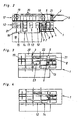
- Plant 1 shown comprises several stations, which are arranged such that the pallet molds 21, on which the precast concrete elements are produced, these stations in the sense of a production line in particular circulating through.
- This production line comprises a de-scaling station 2, in the region of which a demolition cross-piece 3 is arranged. Subsequent to the de-scaling station 2, a shuttering removal station 4 follows, in which the shuttering profiles 10 are removed from the pallet mold 21. This is followed by the cleaning station 6, which is associated with a cleaning and ⁇ lungsvorraum 5.
- the pallet molds 21 are conveyed to the formwork station 7.
- the shells of concrete precast elements by means of a formwork robot 8, which fetches the Abschalprofile 10 from the formwork bearing 9 and positioned on the pallet mold 21 located in the formwork station 7.
- the Abschalprofile 10 go through after removal of the pallet mold 21 in the Schalungsentfemungsstation 4 a transport and cleaning line 22 before they are deposited in the formwork warehouse.
- the formwork station 7 is followed by a blind station 12, at which no work is carried out.
- concreting station 14 which is assigned to the concreting device 13, by means of which the concrete is introduced into the formwork 11.
- the concreting station 14 is again followed by a dummy station 12 and thereupon the reinforcement station 15, in which by means of a positioning device 16, which in the reinforcement preparation station 18th prepared reinforcements in the already concrete, but not yet set concrete prefabricated element can be introduced.
- the recovery station 15 is followed by the pick-up station 17 and possibly another blind station 12.
- the pallet molds 21 are picked up by the pick-up station 17 or the subsequent blind station 12 and brought into the curing chamber 20, where the precast concrete element cures under supply of hot air. After setting of the concrete, the pallet mold 21 is transferred from the curing chamber 20 in the de-scaling station 2 and there begins a new round through the production line.
- Fig. 1b the transport routes between the individual stations of the production line are shown in a synchronous shift.
- the pallet molds 21 are moved within a minute from one station to the next, wherein the displacement takes place synchronously.
- Fig. 1c are the individual work processes, which must be performed during a power stroke whose maximum production time is set in the illustrated embodiment with 3.5 minutes. It is again at the same time on the demoulding station 3 the demoulding of concrete precast element, on the Schalungsentfemungsstation 4 the Abschalprofile be removed, in the cleaning station 6, the pallet molds 21 are cleaned on the formwork station 7, the production of the formwork 11 by means of Abschalprofile 10, concreting the Prefabricated concrete element takes place in the concreting station 14 with any reworking carried out on the blind station 12 can be on the reinforcement station 15, the reinforcements are introduced, while on the pickup 17 any special reinforcements can be introduced.
- the timing of the synchronous shift is composed of the maximum manufacturing time of 3.5 minutes and the transport time of 1 minute, i. the pallet molds 21 are moved every 4.5 minutes between the synchronously connected stations of the production line.
- the pallet molds 21 used in this embodiment are about 8 m long and 3 m wide, with about 88 pallets in a layer through the production line.
- a pallet occupancy of 11.25 m 2 which corresponds to a precast concrete element with a length of 4.5 m and a width of 2.5 m
- a production of about 1,000 m 2 per shift with a duration of 8 working hours can be achieved with the system 1 according to the invention become.
- the effective production time during one shift is 7 hours, while the cleaning time takes 1 hour.
- the system 1 according to the invention the number of personnel required for the monitoring of the plant can be reduced to up to 3 persons, while in plants according to the prior art, in which the feed of the pallet forms was not synchronized, sometimes up to 20 people were necessary ,
- inventive systems 1 differ from the embodiment according to Fig. 1a to 1c only by the local arrangement of the individual stations of the production line, wherein in the embodiment according to Fig. 2 the stacking device 19 is formed by a stacker crane.
- FIG. 3 illustrated embodiment shows a system 1, with the addition of element ceilings and double walls can be made.
- a dummy station 12 is arranged after the concreting station 14, which is associated with a turning device 23 with a turning frame and suction cups.
- the operation of such Wenderahmen is known per se, which is why a description is omitted here.
- FIG. 4 illustrated embodiment differs from the in Fig. 3 shown example only in that just no such turning device 23 is provided, ie the system according to Fig. 4 serves for the production of flat element ceilings.
- Fig. 5a to 5c are different embodiments of inventive formworks 11, which are arranged on a pallet 21, shown.
- at least three of the formwork 11 forming Abschalprofile 10 project beyond the outer peripheral edge U a , in each case to the section A.
- the outer peripheral edge U a is defined by the Abschal vom 24 opposite longitudinal sides of Abschalprofile 10 and is the inner peripheral edge U I geometrically similar.
- the peripheral edge of the formwork 11 is formed by the Abschalprofilen 10, the Abschalvid 24 of Abschalprofile 10 forming the inner peripheral edge U I , while the Abschalvid 24 opposite sides of Abschalprofile 10 are part of the outer peripheral edge U A.
- Fig. 5a stand all Abschalprofile 10 over the outer peripheral edge U A , while in the Fig. 5b and 5c only three Abschalprofile 10 protrude beyond the outer peripheral edge U A.
- Fig. 6 illustrated embodiment of a formwork 11 according to the invention three sides of the peripheral edge U a of Abschalprofilen 10 are formed with a standardized length.
- the fourth side of the formwork 11 with the side length L is in contrast to the embodiments according to Fig. 5a to 5c not formed by a projecting Abschalprofil 10 but rather by two set in series Abschalprofilen 10.
- a corresponding grid of different Standard lengths for Abschalprofile 10 can be switched with this method almost all required side lengths L of a concrete precast element to be manufactured exclusively with Abschalprofilen 10 standardized length.
- Smaller distances between the series-laid Abschalprofilen 10 play no major role, but the distance between the individual Abschalprofilen should not be greater than 1.5 cm usually to avoid spillage of the concrete.
- the laying of Abschalprofile 10 can be done entirely with a formwork robot 8, where it has been found to be particularly advantageous if only one formwork per pallet 21 is arranged, since then the center M of the pallet 21 as a reference point for the shuttering robot. 8 can serve.
- a very short overall time required for the shelling of concrete precast element is achieved, whereby a total of a short cycle time for the synchronous shift and a particularly efficient automation of the pallet circulation system can be achieved.
Landscapes
- Engineering & Computer Science (AREA)
- Chemical & Material Sciences (AREA)
- Ceramic Engineering (AREA)
- Mechanical Engineering (AREA)
- Manufacturing & Machinery (AREA)
- Automation & Control Theory (AREA)
- Devices For Post-Treatments, Processing, Supply, Discharge, And Other Processes (AREA)
Applications Claiming Priority (1)
| Application Number | Priority Date | Filing Date | Title |
|---|---|---|---|
| AT0112107A AT505691A1 (de) | 2007-07-17 | 2007-07-17 | Anlage zur herstellung von betonfertigbauelementen mit einer fertigungsstrasse |
Publications (2)
| Publication Number | Publication Date |
|---|---|
| EP2017049A2 true EP2017049A2 (fr) | 2009-01-21 |
| EP2017049A3 EP2017049A3 (fr) | 2011-05-18 |
Family
ID=39874158
Family Applications (1)
| Application Number | Title | Priority Date | Filing Date |
|---|---|---|---|
| EP08012795A Ceased EP2017049A3 (fr) | 2007-07-17 | 2008-07-16 | Installation de fabrication d'éléments préfabriqués en béton dotées d'une chaîne de production |
Country Status (2)
| Country | Link |
|---|---|
| EP (1) | EP2017049A3 (fr) |
| AT (1) | AT505691A1 (fr) |
Cited By (7)
| Publication number | Priority date | Publication date | Assignee | Title |
|---|---|---|---|---|
| EP2017047A3 (fr) * | 2007-07-17 | 2011-02-16 | Progress Maschinen & Automation AG | Coffrage pour la fabrication d'un élément préfabriqué en béton sur une table de moulage en particulier de forme carré |
| WO2012093282A1 (fr) | 2011-01-05 | 2012-07-12 | Progress Maschinen & Automation Ag | Installation de production avec affichage historique indexé sur le temps |
| EP2878415A3 (fr) * | 2013-11-15 | 2015-10-28 | Elematic Oy Ab | Procédé et installation de fabrication de produits en béton de coulée |
| CN109352816A (zh) * | 2018-12-04 | 2019-02-19 | 杭州江润科技有限公司 | 小型预制构件系统及施工方法 |
| CN109483717A (zh) * | 2018-11-21 | 2019-03-19 | 远大住宅工业(上海)有限公司 | 一种构件生产线 |
| CN110385771A (zh) * | 2019-08-14 | 2019-10-29 | 通榆加亿科技环保建筑材料有限公司 | 一种湿法六工位连续成型高强混凝土制品方法 |
| EP3059057B1 (fr) * | 2015-02-13 | 2020-10-28 | Progress Holding A.G. | Systeme de coffrage destine a fabriquer un coffrage pour un element prefabrique en beton |
Families Citing this family (1)
| Publication number | Priority date | Publication date | Assignee | Title |
|---|---|---|---|---|
| CN107263697B (zh) * | 2017-06-22 | 2020-01-03 | 上海建工材料工程有限公司 | 一种双向可扩展预制构件智能生产线及控制方法 |
Citations (4)
| Publication number | Priority date | Publication date | Assignee | Title |
|---|---|---|---|---|
| DE2338445A1 (de) | 1973-07-28 | 1975-02-13 | Stetter Gmbh | Verfahren und einrichtung zur herstellung von betonbauteilen |
| FR2353377A1 (fr) | 1976-06-04 | 1977-12-30 | Guillemin & Cie Agglos | Installation de production de poutrelles composites |
| GB2127343A (en) | 1982-09-03 | 1984-04-11 | Myrayarn Limited | Improvements in or relating to methods of casting concrete articles |
| DE8814308U1 (de) | 1988-11-15 | 1990-03-15 | Kaspar Röckelein KG, 8602 Wachenroth | Herstellungsgerät für Doppelwände |
-
2007
- 2007-07-17 AT AT0112107A patent/AT505691A1/de not_active Application Discontinuation
-
2008
- 2008-07-16 EP EP08012795A patent/EP2017049A3/fr not_active Ceased
Patent Citations (4)
| Publication number | Priority date | Publication date | Assignee | Title |
|---|---|---|---|---|
| DE2338445A1 (de) | 1973-07-28 | 1975-02-13 | Stetter Gmbh | Verfahren und einrichtung zur herstellung von betonbauteilen |
| FR2353377A1 (fr) | 1976-06-04 | 1977-12-30 | Guillemin & Cie Agglos | Installation de production de poutrelles composites |
| GB2127343A (en) | 1982-09-03 | 1984-04-11 | Myrayarn Limited | Improvements in or relating to methods of casting concrete articles |
| DE8814308U1 (de) | 1988-11-15 | 1990-03-15 | Kaspar Röckelein KG, 8602 Wachenroth | Herstellungsgerät für Doppelwände |
Cited By (10)
| Publication number | Priority date | Publication date | Assignee | Title |
|---|---|---|---|---|
| EP2017047A3 (fr) * | 2007-07-17 | 2011-02-16 | Progress Maschinen & Automation AG | Coffrage pour la fabrication d'un élément préfabriqué en béton sur une table de moulage en particulier de forme carré |
| WO2012093282A1 (fr) | 2011-01-05 | 2012-07-12 | Progress Maschinen & Automation Ag | Installation de production avec affichage historique indexé sur le temps |
| US9383747B2 (en) | 2011-01-05 | 2016-07-05 | Progress Maschinen & Automation Ag | Production installation with time-indexed historical display |
| EP2878415A3 (fr) * | 2013-11-15 | 2015-10-28 | Elematic Oy Ab | Procédé et installation de fabrication de produits en béton de coulée |
| RU2666833C2 (ru) * | 2013-11-15 | 2018-09-12 | Элематик Ойй | Способ и оборудование для отливки бетонных изделий |
| EP3059057B1 (fr) * | 2015-02-13 | 2020-10-28 | Progress Holding A.G. | Systeme de coffrage destine a fabriquer un coffrage pour un element prefabrique en beton |
| CN109483717A (zh) * | 2018-11-21 | 2019-03-19 | 远大住宅工业(上海)有限公司 | 一种构件生产线 |
| CN109352816A (zh) * | 2018-12-04 | 2019-02-19 | 杭州江润科技有限公司 | 小型预制构件系统及施工方法 |
| CN109352816B (zh) * | 2018-12-04 | 2020-09-22 | 杭州江润科技有限公司 | 小型预制构件系统及施工方法 |
| CN110385771A (zh) * | 2019-08-14 | 2019-10-29 | 通榆加亿科技环保建筑材料有限公司 | 一种湿法六工位连续成型高强混凝土制品方法 |
Also Published As
| Publication number | Publication date |
|---|---|
| EP2017049A3 (fr) | 2011-05-18 |
| AT505691A1 (de) | 2009-03-15 |
Similar Documents
| Publication | Publication Date | Title |
|---|---|---|
| EP2119542B1 (fr) | Procédé et machine de fabrication d'éléments préfabriqués en béton, où la fabrication est exécutée sur des moules -palettes | |
| EP2017049A2 (fr) | Installation de fabrication d'éléments préfabriqués en béton dotées d'une chaîne de production | |
| DE2229264C2 (de) | Verfahren zur fabrikmäßigen Herstellung der Geschosse eines Gebäudes und Vorrichtung zur Ausführung des Verfahrens | |
| EP2119541B1 (fr) | Procédé de fabrication d'éléments préfabriqués en béton sur palettes passant les unes après les autres à travers plusieurs stations d'une chaîne de fabrication | |
| EP2017047B1 (fr) | Méhode de sélection d'éléments de coffrage de bordure pour fabriquer un coffrage pour un élément préfabriqué en béton et coffrage correspondant. | |
| DE69003352T2 (de) | Anlage zum Herstellen von anschliessend zur Bildung einer Baueinheit seitlich aneinanderzufügender Raumzellen. | |
| AT400457B (de) | Bauelement sowie verfahren zu dessen herstellung | |
| DE3838711C1 (en) | Process and system for producing double-shelled wall elements | |
| CH630986A5 (de) | Sturz fuer durchgaenge, tuer- und fensteroeffnungen. | |
| AT510233B1 (de) | Verfahren zur herstellung von fertigteilbauteilen | |
| DE3416028C2 (fr) | ||
| EP3299524A1 (fr) | Mur en elements prefabriques et son procede de fabrication | |
| EP4050160A1 (fr) | Procédé de fabrication d'une fondation d'une installation de production, boîte d'ancrage de fondation et installation de production | |
| DE2322139C3 (de) | Batterieform und Verfahren zum Herstellen von Betonplatten | |
| EP0542116A1 (fr) | Elément de coffrage perdu | |
| DE3605373A1 (de) | Verfahren und vorrichtung zum herstellen von mauerwerks-wandelementen | |
| DE2548298C2 (de) | Verfahren und Hohlraumverschalungswand zum Bauen einer Hohlmauer | |
| CH417005A (de) | Bauteilsatz zur Erstellung von Gebäuden aller Art | |
| DE2112977C3 (de) | Verfahren und Vorrichtung zur Herstellung großer paßgerecht aneinander anschließender Fertigbauteile aus Beton | |
| WO2018073325A1 (fr) | Dispositif et procédé pour produire d'un seul tenant un module formant un espace, lequel module présente trois éléments latéraux et un élément formant fond et/ou un élément formant couvercle et module formant espace de ce type | |
| DE2161301B2 (fr) | ||
| DE2635877A1 (de) | Aufzugsschacht fuer wohngebaeude und verfahren zu seiner herstellung | |
| DE4012532A1 (de) | Verfahren zum herstellen eines betonkoerpers fuer bauwerke oder bauwerksteile sowie hierfuer geeignetes betonfertigelement | |
| DE29817726U1 (de) | Vorrichtung zur Herstellung einer Wandtafel | |
| DE3344034A1 (de) | Anlage zur fliessbandfertigung von betonfertigbauteilen, insbesondere von grosstafeln |
Legal Events
| Date | Code | Title | Description |
|---|---|---|---|
| PUAI | Public reference made under article 153(3) epc to a published international application that has entered the european phase |
Free format text: ORIGINAL CODE: 0009012 |
|
| AK | Designated contracting states |
Kind code of ref document: A2 Designated state(s): AT BE BG CH CY CZ DE DK EE ES FI FR GB GR HR HU IE IS IT LI LT LU LV MC MT NL NO PL PT RO SE SI SK TR |
|
| AX | Request for extension of the european patent |
Extension state: AL BA MK RS |
|
| PUAL | Search report despatched |
Free format text: ORIGINAL CODE: 0009013 |
|
| AK | Designated contracting states |
Kind code of ref document: A3 Designated state(s): AT BE BG CH CY CZ DE DK EE ES FI FR GB GR HR HU IE IS IT LI LT LU LV MC MT NL NO PL PT RO SE SI SK TR |
|
| AX | Request for extension of the european patent |
Extension state: AL BA MK RS |
|
| 17P | Request for examination filed |
Effective date: 20111108 |
|
| AKX | Designation fees paid |
Designated state(s): AT BE BG CH CY CZ DE DK EE ES FI FR GB GR HR HU IE IS IT LI LT LU LV MC MT NL NO PL PT RO SE SI SK TR |
|
| 17Q | First examination report despatched |
Effective date: 20120507 |
|
| STAA | Information on the status of an ep patent application or granted ep patent |
Free format text: STATUS: THE APPLICATION HAS BEEN REFUSED |
|
| 18R | Application refused |
Effective date: 20140131 |