EP2017059A2 - Outil de moulage par injection, procédé et installation destinés au moulage par injection d'une section d'une pièce de formage - Google Patents
Outil de moulage par injection, procédé et installation destinés au moulage par injection d'une section d'une pièce de formage Download PDFInfo
- Publication number
- EP2017059A2 EP2017059A2 EP08168031A EP08168031A EP2017059A2 EP 2017059 A2 EP2017059 A2 EP 2017059A2 EP 08168031 A EP08168031 A EP 08168031A EP 08168031 A EP08168031 A EP 08168031A EP 2017059 A2 EP2017059 A2 EP 2017059A2
- Authority
- EP
- European Patent Office
- Prior art keywords
- mold
- jaw
- injection
- locking
- jaws
- Prior art date
- Legal status (The legal status is an assumption and is not a legal conclusion. Google has not performed a legal analysis and makes no representation as to the accuracy of the status listed.)
- Granted
Links
- 238000000034 method Methods 0.000 title claims description 8
- 238000001746 injection moulding Methods 0.000 title abstract description 29
- 238000002347 injection Methods 0.000 claims abstract description 68
- 239000007924 injection Substances 0.000 claims abstract description 68
- 238000000465 moulding Methods 0.000 claims description 32
- 238000007493 shaping process Methods 0.000 claims description 15
- 239000000463 material Substances 0.000 claims description 10
- 239000007921 spray Substances 0.000 claims description 9
- 230000009969 flowable effect Effects 0.000 claims description 5
- 238000006073 displacement reaction Methods 0.000 claims description 4
- 238000005507 spraying Methods 0.000 description 10
- 238000005538 encapsulation Methods 0.000 description 7
- 239000004033 plastic Substances 0.000 description 6
- 238000011161 development Methods 0.000 description 3
- 230000018109 developmental process Effects 0.000 description 3
- 238000004519 manufacturing process Methods 0.000 description 3
- 239000012768 molten material Substances 0.000 description 2
- 239000012815 thermoplastic material Substances 0.000 description 2
- 239000000969 carrier Substances 0.000 description 1
- 238000005266 casting Methods 0.000 description 1
- 238000010276 construction Methods 0.000 description 1
- 230000001419 dependent effect Effects 0.000 description 1
- 230000005484 gravity Effects 0.000 description 1
- 238000002372 labelling Methods 0.000 description 1
- 230000014759 maintenance of location Effects 0.000 description 1
- 238000003825 pressing Methods 0.000 description 1
- 230000002787 reinforcement Effects 0.000 description 1
- 238000009964 serging Methods 0.000 description 1
- 239000000243 solution Substances 0.000 description 1
- 229920001169 thermoplastic Polymers 0.000 description 1
- 239000004416 thermosoftening plastic Substances 0.000 description 1
Images


Classifications
-
- B—PERFORMING OPERATIONS; TRANSPORTING
- B29—WORKING OF PLASTICS; WORKING OF SUBSTANCES IN A PLASTIC STATE IN GENERAL
- B29C—SHAPING OR JOINING OF PLASTICS; SHAPING OF MATERIAL IN A PLASTIC STATE, NOT OTHERWISE PROVIDED FOR; AFTER-TREATMENT OF THE SHAPED PRODUCTS, e.g. REPAIRING
- B29C45/00—Injection moulding, i.e. forcing the required volume of moulding material through a nozzle into a closed mould; Apparatus therefor
- B29C45/17—Component parts, details or accessories; Auxiliary operations
- B29C45/26—Moulds
- B29C45/33—Moulds having transversely, e.g. radially, movable mould parts
-
- B—PERFORMING OPERATIONS; TRANSPORTING
- B29—WORKING OF PLASTICS; WORKING OF SUBSTANCES IN A PLASTIC STATE IN GENERAL
- B29C—SHAPING OR JOINING OF PLASTICS; SHAPING OF MATERIAL IN A PLASTIC STATE, NOT OTHERWISE PROVIDED FOR; AFTER-TREATMENT OF THE SHAPED PRODUCTS, e.g. REPAIRING
- B29C45/00—Injection moulding, i.e. forcing the required volume of moulding material through a nozzle into a closed mould; Apparatus therefor
- B29C45/14—Injection moulding, i.e. forcing the required volume of moulding material through a nozzle into a closed mould; Apparatus therefor incorporating preformed parts or layers, e.g. injection moulding around inserts or for coating articles
- B29C45/14336—Coating a portion of the article, e.g. the edge of the article
-
- B—PERFORMING OPERATIONS; TRANSPORTING
- B29—WORKING OF PLASTICS; WORKING OF SUBSTANCES IN A PLASTIC STATE IN GENERAL
- B29C—SHAPING OR JOINING OF PLASTICS; SHAPING OF MATERIAL IN A PLASTIC STATE, NOT OTHERWISE PROVIDED FOR; AFTER-TREATMENT OF THE SHAPED PRODUCTS, e.g. REPAIRING
- B29C45/00—Injection moulding, i.e. forcing the required volume of moulding material through a nozzle into a closed mould; Apparatus therefor
- B29C45/17—Component parts, details or accessories; Auxiliary operations
- B29C45/64—Mould opening, closing or clamping devices
-
- B—PERFORMING OPERATIONS; TRANSPORTING
- B29—WORKING OF PLASTICS; WORKING OF SUBSTANCES IN A PLASTIC STATE IN GENERAL
- B29C—SHAPING OR JOINING OF PLASTICS; SHAPING OF MATERIAL IN A PLASTIC STATE, NOT OTHERWISE PROVIDED FOR; AFTER-TREATMENT OF THE SHAPED PRODUCTS, e.g. REPAIRING
- B29C45/00—Injection moulding, i.e. forcing the required volume of moulding material through a nozzle into a closed mould; Apparatus therefor
- B29C45/17—Component parts, details or accessories; Auxiliary operations
- B29C45/40—Removing or ejecting moulded articles
- B29C45/42—Removing or ejecting moulded articles using means movable from outside the mould between mould parts, e.g. robots
- B29C2045/425—Single device for unloading moulded articles and loading inserts into the mould
-
- B—PERFORMING OPERATIONS; TRANSPORTING
- B29—WORKING OF PLASTICS; WORKING OF SUBSTANCES IN A PLASTIC STATE IN GENERAL
- B29C—SHAPING OR JOINING OF PLASTICS; SHAPING OF MATERIAL IN A PLASTIC STATE, NOT OTHERWISE PROVIDED FOR; AFTER-TREATMENT OF THE SHAPED PRODUCTS, e.g. REPAIRING
- B29C45/00—Injection moulding, i.e. forcing the required volume of moulding material through a nozzle into a closed mould; Apparatus therefor
- B29C45/14—Injection moulding, i.e. forcing the required volume of moulding material through a nozzle into a closed mould; Apparatus therefor incorporating preformed parts or layers, e.g. injection moulding around inserts or for coating articles
- B29C45/14008—Inserting articles into the mould
-
- B—PERFORMING OPERATIONS; TRANSPORTING
- B29—WORKING OF PLASTICS; WORKING OF SUBSTANCES IN A PLASTIC STATE IN GENERAL
- B29C—SHAPING OR JOINING OF PLASTICS; SHAPING OF MATERIAL IN A PLASTIC STATE, NOT OTHERWISE PROVIDED FOR; AFTER-TREATMENT OF THE SHAPED PRODUCTS, e.g. REPAIRING
- B29C45/00—Injection moulding, i.e. forcing the required volume of moulding material through a nozzle into a closed mould; Apparatus therefor
- B29C45/16—Making multilayered or multicoloured articles
-
- B—PERFORMING OPERATIONS; TRANSPORTING
- B29—WORKING OF PLASTICS; WORKING OF SUBSTANCES IN A PLASTIC STATE IN GENERAL
- B29C—SHAPING OR JOINING OF PLASTICS; SHAPING OF MATERIAL IN A PLASTIC STATE, NOT OTHERWISE PROVIDED FOR; AFTER-TREATMENT OF THE SHAPED PRODUCTS, e.g. REPAIRING
- B29C45/00—Injection moulding, i.e. forcing the required volume of moulding material through a nozzle into a closed mould; Apparatus therefor
- B29C45/17—Component parts, details or accessories; Auxiliary operations
- B29C45/26—Moulds
- B29C45/27—Sprue channels ; Runner channels or runner nozzles
-
- B—PERFORMING OPERATIONS; TRANSPORTING
- B29—WORKING OF PLASTICS; WORKING OF SUBSTANCES IN A PLASTIC STATE IN GENERAL
- B29C—SHAPING OR JOINING OF PLASTICS; SHAPING OF MATERIAL IN A PLASTIC STATE, NOT OTHERWISE PROVIDED FOR; AFTER-TREATMENT OF THE SHAPED PRODUCTS, e.g. REPAIRING
- B29C45/00—Injection moulding, i.e. forcing the required volume of moulding material through a nozzle into a closed mould; Apparatus therefor
- B29C45/17—Component parts, details or accessories; Auxiliary operations
- B29C45/40—Removing or ejecting moulded articles
- B29C45/42—Removing or ejecting moulded articles using means movable from outside the mould between mould parts, e.g. robots
-
- B—PERFORMING OPERATIONS; TRANSPORTING
- B29—WORKING OF PLASTICS; WORKING OF SUBSTANCES IN A PLASTIC STATE IN GENERAL
- B29L—INDEXING SCHEME ASSOCIATED WITH SUBCLASS B29C, RELATING TO PARTICULAR ARTICLES
- B29L2031/00—Other particular articles
- B29L2031/30—Vehicles, e.g. ships or aircraft, or body parts thereof
-
- B—PERFORMING OPERATIONS; TRANSPORTING
- B29—WORKING OF PLASTICS; WORKING OF SUBSTANCES IN A PLASTIC STATE IN GENERAL
- B29L—INDEXING SCHEME ASSOCIATED WITH SUBCLASS B29C, RELATING TO PARTICULAR ARTICLES
- B29L2031/00—Other particular articles
- B29L2031/46—Knobs or handles, push-buttons, grips
- B29L2031/463—Grips, handles
-
- B—PERFORMING OPERATIONS; TRANSPORTING
- B29—WORKING OF PLASTICS; WORKING OF SUBSTANCES IN A PLASTIC STATE IN GENERAL
- B29L—INDEXING SCHEME ASSOCIATED WITH SUBCLASS B29C, RELATING TO PARTICULAR ARTICLES
- B29L2031/00—Other particular articles
- B29L2031/712—Containers; Packaging elements or accessories, Packages
- B29L2031/7134—Crates, e.g. for bottles
Definitions
- the invention relates to an injection mold having a nozzle part which comprises at least two mutually adjustable mold jaws which delimit a cavity in the injection position, in which an injection channel opens, and with the mold jaws interacting closing elements for holding the mold jaws in the injection position.
- the invention relates to an injection mold having a nozzle part which comprises at least two mold jaws which are adjustable relative to one another and which delimit a cavity in the injection position in which an injection channel opens, and at least one closing element interacting with at least one mold jaw which is adjustably arranged on the nozzle part the mold jaws in the spray position.
- the invention relates to a system for encapsulating a portion of a molded part and / or for injecting a portion of a molding with an injection mold.
- the invention relates to a method for injection molding a portion of a molded part and / or molding a portion of a molded part by injection molding, wherein the molded part is partially introduced into one of mutually adjustable by a nozzle part of an injection mold outgoing mold cavity surrounded cavity in the after Close the mold jaws molten material is injected.
- the injection molding tool used consists of a nozzle part and a molded part, are held by the syringes to be sprayed portion of the box-shaped container receiving mold jaws in the spray position to exclude an adjustment during spraying.
- a nozzle part and a closing part injection mold An existing of a nozzle part and a closing part injection mold is the US-A-5,422,059 refer to.
- the closing part is adjustable to the nozzle part via a hydraulic cylinder.
- the closure member is guided along spars emanating from the nozzle member.
- An existing nozzle part and closing part tool is also from the DE-A-199 32 515 known. With the appropriate tool, they can spray boxes with sturdy handles.
- JP-A-01072815 moldings are produced by injection molding, wherein a cavity is limited by mold jaws, which are held together by clamping in a holder.
- the mold jaws are pressed by means of a nozzle part in the holder.
- the outer surfaces of the mold jaws and thus the inner surfaces of the holder have a cone shape.
- An injection mold after the FR-B-1 076 318 is intended for spraying annular objects.
- a variety of over toggle adjustable outer mold jaws are adjustable to form a closed forming a ring mold jaw.
- the outer mold jaws can be adjusted via cylinders.
- the present invention is based on the problem of developing an injection mold of the type mentioned above and a system involving a corresponding injection mold and a method such that in a compact design easily a molding such as box or motor vehicle part such as wheel arch can be at least partially encapsulated in order To achieve desired material properties in this area or to change the shape of geometric shape in one or more desired areas as extend. It should also be an application regardless of the place of manufacture of the molding itself possible.
- an injection mold having a nozzle part which comprises at least two mold jaws which are adjustable relative to one another and which delimit a cavity in the injection position in which an injection channel opens, and at least one interlock which interacts with at least one mold jaw adjustably arranged on the nozzle part - Or closing element for locking the mold jaws in the spray position, wherein the at least one locking or closing element emanating from the nozzle part, is designed to be adjustable and locked at least one mold jaw in its injection position and wherein a shaping jaw is a contour core, which is characterized in that the shaping jaw forming the contour core proceeds stationarily from a mold carrier of the nozzle part such that at least one shaping jaw is adjustably arranged relative to the contour core and that the locking mechanism or closing element in the closed position of the contour of the contour block is positively connected to the at least one mold block.
- a solution provides a method for injecting a portion of a molded part and / or molding a portion of a molded part, such as motor vehicle part, in particular wheel arch or subfloor, wherein the molded part in sections in one of relatively adjustable from a nozzle part of an injection mold outgoing mold cavity surrounded cavity is introduced, at least one of the mold jaws is locked by means of at least one outgoing from the nozzle member closing element by adjusting this to the at least one mold jaw in its injection position and in the cavity after closing the mold jaws (injection position) flowable material is injected, which is characterized in that the mold part is arranged on one of the mold jaws designed as a stationary mold jaw arranged on a mold carrier of the nozzle part, at least one mold jaw is adjusted to the mold core for forming the cavity, and then the at least one e is locked to the mandrel by positive engagement of the locking or closing element.
- the closing part To remove the manufactured injection-molded part, the closing part must be spaced from the nozzle part to an extent that the molded part can be removed from the space between the nozzle part and closing part.
- the nozzle part and closing part must be axially spaced from each other such that the clear distance is greater than the extension of the injection-molded part in the axial direction.
- the invention goes from the nozzle member itself to hold the mold or the jaws required adjustable closing element, so that a very compact injection mold is provided, which can thus be used there without great mechanical effort, where z. B. a portion of a molded part such as boxes to be encapsulated.
- a molded part such as boxes to be encapsulated.
- teaching of the invention is not limited solely to an injection mold with which a molded part or a portion of such a molded or a section can be sprayed. Rather, the teaching is also suitable in principle for spraying molded parts per se.
- the shaping jaw interacts with at least one closing element in the form of a locking wedge, the forming jaw and the locking wedge being positively and non-positively connected in the closed position via inclined inclined surfaces to the adjustment path of the locking wedge in order to prevent self-locking in this manner to realize.
- the surfaces lying on one another have a sawtooth-shaped geometry.
- the surface has a plurality of at least a first, a second and a third portion comprising areas, wherein the first portion transverse to the displacement of the locking wedge, the second portion in the direction of the displacement of the locking wedge and connecting the sections third section along extend the structured surface spanned plane.
- the order of the sections may differ. Further, the first and third portions of the superimposed surfaces of locking wedge and form jaw are always spaced from each other.
- the second section of the areas forming the sawtooth-shaped geometry of the surfaces of the shaping jaw and the locking wedge are preferably parallel to the adjustment path of the locking wedge, the second section can also be an angle ⁇ to the adjustment path, in particular ⁇ ⁇ 6 °, preferably 5 ° ⁇ ⁇ ⁇ Enclose 6 °.
- At least one engaging in the mold jaw driver starts from the locking wedge, wherein for unlocking the jaw of the locking wedge is adjustable with this game.
- a first movement of the locking wedge in order then to take along the mold jaw. This ensures that when closing the locking wedge of the required form fit to the jaw is reached.
- the shaping jaw has, in its region facing the locking wedge, a cut in the form of a T-shaped recess into which the T-shaped driver runs with play.
- the cavity surrounded by the mold jaws for encapsulating a portion of a molded part is further designed such that the cavity is at least partially spaced surrounds the portion to be overmoulded.
- the cavity may also circumferentially surround the portion spaced.
- the extent of the portion of the molding within the cavity to which the portion is to be molded is often considerably smaller than the remaining space into which the molten material is injected.
- the contour core at least one mold jaw is preferably adjustably arranged via a first pressure cylinder connected to the mold carrier that of the mold carrier, the at least one preferably via a with the Mold support associated second pressure cylinder adjustable locking element goes out, which is positively connected in the closed position of the contour rake with the forming jaw and preferably engages in a recess of the mold jaw.
- the adjustment path of the shaping jaw can run transversely, in particular perpendicular to the adjustment path of the locking element.
- the teaching according to the invention makes it possible to inject portions even on large shaped parts or to overmold sections of the molded part itself.
- the molded part to be molded on or around can be positioned on a contoured core to be designated as a stationary mold jaw, to which a plurality of mold jaws are adjustable, which in turn close a mold cavity in the closed position on the outside.
- the adjustable mold jaws can be arranged in a star shape around a contour core, wherein the mold jaws in the closed position flush in the area merge into each other, in which the mold cavity is limited.
- the adjustment of the contour ridges can be done via pressure as hydraulic cylinder, which depends on the nozzle part, d. H. whose mold carriers go out.
- each mold jaw is associated with a locking element which engages in particular a form-fitting manner in a recess of the mold jaw.
- adjustment of each mold jaw to the adjustment of the associated locking element preferably perpendicular to each other.
- the adjustment path of the shaping jaw can run parallel to the plane spanned by the mold carrier, whereas the adjustment path of the locking element extends perpendicular to the plane.
- the locking element is embedded with this adjustable pressure cylinder in the mold carrier.
- Intervention in the mold jaws also means interacting with the piston or another element which can be moved with the mold jaw.
- the box-shaped molded part to be encapsulated such as a bottle crate
- a conveying device such as a conveyor belt
- outgoing from the handling device support beams in the corresponding spars of the box-shaped molding, so that when spraying an impermissible deformation is excluded.
- the supporting spars engaging in the spars serve to grasp the box-shaped molding.
- the system comprises at least two mutually aligned and in the region of the injection molding over a gap spaced apart conveyors, that the gap is closed by a receptacle with which the molded part can be transferred to the injection mold or removed from this is, and that the molded part is closed by closed by the recording space on this by means of one of the conveyors transported further molded parts.
- the molded part which is partly to be encapsulated, can be aligned with the injection mold with structurally simple measures in order then to transfer the molded part to the injection molding tool by means of the receptacle performing the function of a handling device or to remove it therefrom.
- the receptacle may preferably be designed as a lifting device such as lifting table, so that consequently the injection mold is arranged vertically above the conveying path of the molded part.
- the injection molding tool starts from a holder plate, from which a second injection molding tool having a nozzle part and a closing part emanates, by means of which the molded part itself is injected.
- a second injection molding tool having a nozzle part and a closing part emanates, by means of which the molded part itself is injected.
- the mold jaws are locked or released in the nozzle part in the usual way.
- the molded part is transferred into the nozzle part of the first injection molding tool via a handling device.
- the invention is characterized by a method for injecting a portion of a molded part and / or molding a portion of a molded part by injection molding, wherein the molded part partially inserted into one of mutually adjustable from a nozzle part of an injection molding and outgoing and relatively adjustable mold cavity surrounded cavity is, in the after closing of the mold jaws (injection position) flowable material is injected, characterized in that at least one of the mold jaws is locked by means of at least one of the nozzle part outgoing closing element by adjusting this to the at least one mold jaw in its injection position, which is provided in particular that the forming jaws be held by means of the nozzle part outgoing closing elements by adjusting this to the mold jaws by self-locking in their spray position.
- FIGS. 1 to 14 Preferred embodiments or arrangements and sections of systems for spraying molded parts or for encapsulating sections of molded parts or injection molding of sections of molded parts are explained.
- a bottle crate is assumed to be a molded part, without the teaching of the invention being restricted thereby.
- any object can be used from a suitable material to which a section molded or a section can be encapsulated.
- a section of the molded part itself is at least partially encapsulated.
- plastic parts of the motor vehicle industry such as wheel arch liners or motor vehicle underbody linings are also suitable as shaped parts, for example only to mention a few items.
- FIG. 1 a detail of a system 10 for encapsulating a handle 12 of a box 14 can be seen, which is transported along a transport path 16, which may be formed by a conveyor belt, and then inserted by means of a handling device 18 in an injection mold 20, in which the handle 12 overmolded becomes.
- the handle 12 may be one which is present in a side wall of the box 14, but may also be a center handle, as exemplified in connection with FIGS Fig. 9 . 13 and 14 is explained.
- the injection molding tool 20 is connected to an extruder 22, via which thermoplastic material which is flowable in a known manner is supplied to the injection molding tool 20 or to nozzles present in it.
- the injection molding tool 20 consists solely of a nozzle part, without requiring the separate closing part required according to the prior art.
- the unit consisting of the injection mold 20 and the extruder 22 can thereby be made compact, so that use at desired locations can be done easily, so it is not absolutely necessary that the injection mold 20 is used where the box itself is injected ,
- this provides the possibility that the molding to be encapsulated or to be sprayed can protrude to a considerable extent over the nozzle part, since a disability is not given by a closing part.
- a problem-free removal of the molded part from the injection mold 20 can also take place since, as mentioned, a closing part does not have to be previously spaced from the nozzle part in order to be able to remove the molded part from the injection mold.
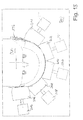
- FIG. 2 is to take a plan view of a system 24 comprising a plurality of injection molds 26, 28, 30 with associated extruders 32, 34, 36, with which boxes 38, 40, 42 are to be encapsulated in the required extent.
- About handling devices 44, 46, 48, the boxes 38, 40, 42 are inserted into the tools 26, 28, 30 and removed.
- the boxes 38, 40, 42 via a Conveyor belt 50 in the required position between the respective handling device 44, 46, 48 and the associated tool 26, 28, 30 moves.
- Fig. 3 is a detail of Annex 10 or 24 refer to. It can be seen on a conveyor belt 52 arranged boxes 54, 56 to be overmolded. In this case, the outer handles 58, 60, middle handles, not shown, or wall sections such as in particular inner wall sections can be encapsulated.
- a handling device 62 which, starting from a pivotable arm 64, comprises a base plate 66 with support posts 68, 70, 72, 74 emanating therefrom, which can be inserted into the corner posts of the box are. Furthermore, the handling device 62 has mutually adjustable side arms 76, 78 to laterally engage the box 56.
- the tool 80 has largely a classic structure with a mold carrier 82 and mold jaws, between which a portion of the box 46 can be introduced to partially surround the portion to be encapsulated by a cavity in the flowable for encapsulation thermoplastic material via a nozzle, not shown is injected.
- a mold carrier 82 and mold jaws, between which a portion of the box 46 can be introduced to partially surround the portion to be encapsulated by a cavity in the flowable for encapsulation thermoplastic material via a nozzle, not shown is injected.
- two corresponding mold jaws in Fig. 4 designated by the reference numerals 84, 86.
- the mold jaws 84, 86 To close the mold jaws 84, 86 and hold or open, ie move away from each other, the mold jaws 84, 86 cooperate with locking wedges 88, 90, are held over the mold jaws 84, 86 in the spray position.
- a closing part is assigned to the nozzle part, via which the locking wedges 88, 90 are locked
- locking takes place without a closing part, resulting in a very compact structural unit for the tool 80.
- the locking or rather locking the mold jaws 84, 86 is technically realized by the fact that the locking wedges 88, 90 in the injection position, ie with closed mold jaws 84, 86 rest on the outside of the forming jaws 84, 86, as in connection with the FIGS. 10 and 11 is explained in more detail.
- FIG. 7 is a schematic view of a section of an injection mold to remove to encase inner wall areas of boxes.
- a mold carrier 92 according to the principal explanations according to the Fig. 4
- Form jaws and associated locking wedges which are exemplified by the reference numerals 94, 96 for the mold jaws and 98, 100 for the locking wedges.
- the mold jaws 94, 96 cooperate in the injection position, ie in the closed mold, in a self-locking manner with the associated locking wedges 98, 100, so that a locking takes place exclusively via the nozzle part of the injection molding tool without the need for a closing part.
- Fig. 8 is shown a section of a tool with which a center handle of a box is overmoulded.
- only two mold jaws 102 and these associated locking wedges 104 are required, which in turn along guide blocks 106, 108 are adjustable to the required movement perpendicular to a the mold jaws 102 and the locking wedges 104 receiving mold carrier 110 spanned level to open or close and locking the mold jaws 102 to adjust.
- a tool 112 which also includes only a nozzle part in which existing handles are to be encapsulated in the side walls of a box.
- the tool 112, that is, the nozzle part comprises a mold carrier 114 with locking wedges which are adjustable perpendicular to the plane which is clamped in front of the latter and by way of which the handles or mold jaws receiving on these adjoining regions of the box are adjustable.
- the guide of the locking wedges 120 takes on an outer wall portion of the mold carrier, ie with respect to the locking wedge 120 of the right wall portion 124 of the mold carrier 114.
- the inner locking wedges 122 are guided by guide jaws, not shown, which may also be sections of the bottom wall 114 of the mold carrier.
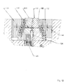
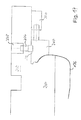
- a section of a nozzle part of an injection mold is shown. It can be seen two mutually adjustable mold jaws 126, 128 and associated therewith locking wedges 130, 132. The directions of movement of the forming jaws 126, 128 and the locking wedges 130, 132 are symbolized by the double arrows.
- the Fig. 10 In closed position, the Fig. 10 can be seen, are the mold jaws 126, 128 on an inner surface to each other and enclose a cavity 134 in which a portion of the box 54, 56 to be encapsulated is introduced, in the embodiment of the Fig. 10 a side handle.
- the cavity 134 surrounds the side handle in regions spaced so as to overmold remaining cavity with the supplied via a nozzle 136 thermoplastic. This is in particular a softer material compared to the material of the box in order to achieve comfortable wearing properties.
- the locking wedges 130, 132 rest on the outer surfaces of the mold jaws 126, 128 in a self-locking manner. This is the clipping of the Fig. 11 to take closer.
- Fig. 11 is a section of in Fig. 10 shown on the right mold jaw 128 and the associated associated locking wedge 132.
- the mold jaw 128 and the locking wedge 132 are in the closed position over surfaces 134 and 136 self-locking, so that when injecting the plastic material, a pressing apart of the mold jaws 126, 128 is prevented without a separate closing part - as in conventional injection molds - is required.
- the boundary surfaces 134, 136 have a kind of sawtooth structure. This can be realized by successive areas of first, second and third sections.
- a second section 142 extends along the adjustment direction (double arrow 144) of the locking wedge 132.
- a third section 146 which extends extends along a plane which is spanned by the respective surface 134 and 136 of the locking wedge 32 and the form of jaw 128 in the middle, so the overall course of the surface 134 and 136 corresponds. It then joins areas with corresponding sections 138, 142, 146 to form the tooth structure of the surface 136.
- a corresponding structure has the surface 134 of the mold jaw 128, but with superimposed surfaces 134, 136, the first sections 138, 139 and the third Sections 146, 147 spaced from each other.
- the second sections 142, 143 are adjacent to one another in sections.
- self-locking is achieved in the closed position by the second sections 142, 143, wherein the second section 142, 143 does not necessarily have to run parallel to the adjustment direction 144 of the locking wedge 132, but may include an angle ⁇ to the latter, but smaller than 6 °, especially in the range between 5 and 6 °.
- the locking wedge 132 - and thus also the locking wedge 130 - causes not only the locking of the mold jaws 126, 128, but also their movement, ie the moving apart (double arrow 140).
- the locking wedge 132 engages with a cut-T-shaped driver 148 in a corresponding in section T-shaped recesses 150 of the mold jaw 128, as the cutout in Fig. 11a can be seen.
- T-shaped driver 148 is arranged with play in the receptacle 150 so that the opening of the tool initially an adjustment of the locking wedges 130, 132 takes place in the direction of the double arrow 144 without the mold jaws 126, 128 are taken immediately. Only when the driver 148 rests with its transverse leg 152 on the associated locking wedge-side inner surface 154 of the recess 150, the mold jaws 126, 128 are moved along the double arrow 140, whereby the mold can be opened and thus the box or the overmolded handle can be removed.
- the driver 148 is strip-shaped and extends parallel to the averaged from the sections 138, 139, 142, 143, 146, 147 surfaces 134, 136th
- a further embodiment of the teaching of the invention will be explained.
- a second injection tool 158 consisting of a nozzle member 160 and a closure member 162 is provided, with which the box itself is injected.
- the box is inserted by means of a handling device, not shown, in the tool 157, for example, to overmold a center handle.
- the second tool 158 can thereby have a conventional construction to inject boxes so that it does not require further action.
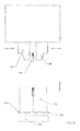
- a lifting device 172 is provided, via which the box 170 is raised or lowered.
- the lifting device 172 in this case comprises a plate-shaped portion 174, on which the box 170 is positioned.
- the lifting device 172 runs between conveyor belts that terminate at a distance from each other, wherein the portion 174 closes the intermediate space when the box 170 is lowered. This provides the possibility that the box 170 is transferred from the plate 174 to an adjacent conveyor belt by the transport of boxes of the other conveyor belt.
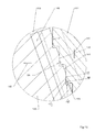
- the molded part 196 is a wheel arch, ie a motor vehicle part.
- the injection molding tool has a nozzle part 200, from which mold jaws and locking elements to be described in more detail below, without the need for a separate and separable closing part which can be adjusted to the nozzle part 200.
- the nozzle part 200 has a mold carrier 202 on which a mold core 204 formed as a stationary mold jaw is arranged, the outer contour of which corresponds to the inner contour of the wheel arch shell 196 to the extent that the area to which the rim 198 is to be injection-molded is positively connected between the contour ram 204 and adjustable to the contour contour mold jaws 206, 208, 210, 212, 214 is received. In doing so, the in Fig.
- the edge 198 is molded onto the molding 196.
- the edge 198 is not only molded butt-shaped to the portion 197 of the wheel arch 196, but extends in sections overlapping the adjacent longitudinal side edges of the portion 197, as in principle the Fig. 18 can be seen.
- piston-cylinder units 216, 218, 220, 222, 224 which are preferably operated hydraulically.
- the mold jaws 206, 208, 210, 212, 214 are arranged in a quasi-star shape around the contoured core 204 and adjustable relative thereto, wherein in the closed position (FIG. Fig. 15 . 16 . 17 . 18 ), the molding jaws 206, 208, 210, 212, 214 in their cavity side extending portions flush with each other, so that plastic from the cavity 215 can not escape.
- each mold jaw 206, 208, 210, 212, 214 is associated with a locking element 226 in the form of a slide, which is also adjustable via a piston-cylinder arrangement 228, wherein preferably a hydraulic cylinder is used.
- the slider or locking piston 226 has at its free end a cuboid to the free end face tapered locking portion which at in Injection position located mold jaw 206, 208, 210, 212, 214 engages positively in a corresponding recess 230.
- the arrangement of the contoured core 204 and the mold jaws 206, 208, 210, 212, 214 and the locking piston 226 which are adjustable with respect to this ensures that, even if the pressure in the piston-cylinder units 216, 218, 220, 222, 224, 228 in FIG Incident should fall, the mold jaws 206, 208, 210, 212, 214 remain locked in the spray position, since the locking piston 226 by gravity in the recesses 230 of the mold blocks 206, 208, 210, 212, 214 remain.
- Fig. 19 is the nozzle member 200 with the tool open, so to the contour core 204 spaced mold jaws 206, 208, 210, 212, 214 shown. In this position, the locking piston 226 is retracted, so that a free movement of the molding jaws 206, 208, 210, 212, 214 is made possible.
Landscapes
- Engineering & Computer Science (AREA)
- Manufacturing & Machinery (AREA)
- Mechanical Engineering (AREA)
- Moulds For Moulding Plastics Or The Like (AREA)
- Injection Moulding Of Plastics Or The Like (AREA)
- Processing And Handling Of Plastics And Other Materials For Molding In General (AREA)
- Slide Fasteners, Snap Fasteners, And Hook Fasteners (AREA)
- Diaphragms For Electromechanical Transducers (AREA)
- Pens And Brushes (AREA)
Priority Applications (1)
| Application Number | Priority Date | Filing Date | Title |
|---|---|---|---|
| PL08168031T PL2017059T3 (pl) | 2004-07-10 | 2005-07-08 | Forma wtryskowa i sposób wtryskowego formowania kształtek |
Applications Claiming Priority (2)
| Application Number | Priority Date | Filing Date | Title |
|---|---|---|---|
| DE102004033461A DE102004033461A1 (de) | 2004-07-10 | 2004-07-10 | Spritzgießwerkzeug sowie Anlage zum Spritzen eines Abschnitts eines Kastens |
| EP05014892A EP1632329B1 (fr) | 2004-07-10 | 2005-07-08 | Moule et procédé pour produire par injection une partie d'un objet |
Related Parent Applications (2)
| Application Number | Title | Priority Date | Filing Date |
|---|---|---|---|
| EP05014892A Division EP1632329B1 (fr) | 2004-07-10 | 2005-07-08 | Moule et procédé pour produire par injection une partie d'un objet |
| EP05014892.3 Division | 2005-07-08 |
Publications (3)
| Publication Number | Publication Date |
|---|---|
| EP2017059A2 true EP2017059A2 (fr) | 2009-01-21 |
| EP2017059A3 EP2017059A3 (fr) | 2009-02-18 |
| EP2017059B1 EP2017059B1 (fr) | 2010-09-01 |
Family
ID=35501447
Family Applications (2)
| Application Number | Title | Priority Date | Filing Date |
|---|---|---|---|
| EP05014892A Expired - Lifetime EP1632329B1 (fr) | 2004-07-10 | 2005-07-08 | Moule et procédé pour produire par injection une partie d'un objet |
| EP08168031A Expired - Lifetime EP2017059B1 (fr) | 2004-07-10 | 2005-07-08 | Outil et procédé destinés au moulage par injection d'une section d'une pièce de formage |
Family Applications Before (1)
| Application Number | Title | Priority Date | Filing Date |
|---|---|---|---|
| EP05014892A Expired - Lifetime EP1632329B1 (fr) | 2004-07-10 | 2005-07-08 | Moule et procédé pour produire par injection une partie d'un objet |
Country Status (6)
| Country | Link |
|---|---|
| EP (2) | EP1632329B1 (fr) |
| AT (2) | ATE413959T1 (fr) |
| DE (3) | DE102004033461A1 (fr) |
| ES (2) | ES2317108T3 (fr) |
| PL (2) | PL2017059T3 (fr) |
| PT (2) | PT1632329E (fr) |
Cited By (1)
| Publication number | Priority date | Publication date | Assignee | Title |
|---|---|---|---|---|
| DE102013227054A1 (de) * | 2013-12-23 | 2015-06-25 | Robert Bosch Gmbh | Stator mit einer Umspritzung und elektrische Maschine mit dem Stator |
Families Citing this family (7)
| Publication number | Priority date | Publication date | Assignee | Title |
|---|---|---|---|---|
| DE102005059976B4 (de) | 2005-12-13 | 2019-10-17 | Delbrouck Gmbh | Verfahren und Spritzgußform zur Herstellung eines Transportkastens aus Kunststoff |
| DE102007047922A1 (de) | 2007-12-12 | 2009-06-18 | Icos Gmbh | Flaschenkasten |
| DE102008015382A1 (de) * | 2008-03-20 | 2009-09-24 | Linpac Allibert Gmbh | Einstückig aus Kunststoff hergestellter Flaschenträger und zu seiner Herstellung dienendes Formwerkzeug |
| DE102008002985A1 (de) | 2008-08-01 | 2010-02-11 | Icos Gmbh | Spritzgießvorrichtung sowie Verfahren zum Spritzgießen |
| DE102016122077A1 (de) * | 2016-11-17 | 2018-05-17 | Schoeller Allibert Gmbh | Verfahren und Vorrichtung zur Labelanordnung auf einem Kasten, insbesondere Flaschenkasten |
| JP7053063B1 (ja) * | 2020-10-20 | 2022-04-12 | 株式会社国盛化学 | 成型システム |
| CN112406041B (zh) * | 2020-10-30 | 2022-08-30 | 石招军 | 一种抽芯长度可调的注塑模具 |
Citations (12)
| Publication number | Priority date | Publication date | Assignee | Title |
|---|---|---|---|---|
| FR1076318A (fr) | 1953-03-10 | 1954-10-26 | Perfectionnements aux moules pour pièces circulaires réalisées en matière plastique | |
| US3358333A (en) | 1965-04-30 | 1967-12-19 | United Shoe Machinery Corp | Two-station injection sole molding machines |
| DE3446020A1 (de) | 1984-12-17 | 1986-06-19 | Peguform-Werke GmbH, 7805 Bötzingen | Verfahren zur herstellung von spritzgussteilen aus kunststoff |
| JPS6472815A (en) | 1987-09-14 | 1989-03-17 | Ricoh Kk | Parting injection molding process |
| DE4022884A1 (de) | 1990-07-18 | 1992-01-23 | Schoeller Plast Ag | Flaschenkasten aus kunststoff |
| US5422059A (en) | 1993-06-14 | 1995-06-06 | Hettinga; Siebolt | Method for injection molding a plastic part using a film gate |
| JPH0866950A (ja) | 1994-08-30 | 1996-03-12 | Sony Corp | 射出成形装置及び射出成形方法 |
| EP1000865A1 (fr) | 1998-10-22 | 2000-05-17 | D.W. PLASTICS, naamloze vennootschap | Casier en plastique avec au moins une poignée |
| DE19932515A1 (de) | 1999-07-12 | 2001-01-18 | Theysohn Friedrich Fa | Kasten aus Kunststoff und Vorrichtung zur Herstellung eines Kastens |
| JP2001058339A (ja) | 1999-08-20 | 2001-03-06 | Toyota Motor Corp | 型締装置 |
| DE10208845A1 (de) | 2002-03-03 | 2003-09-11 | Oberland Engineering Gmbh | Verfahren zum Herstellen eines Kastens und danach hergestellter Kasten |
| EP1396329A1 (fr) | 2002-09-09 | 2004-03-10 | THEYSOHN Formenbau GmbH | Procédé et appareil pour produire une section d'un conteneur en forme de boíte et conteneur ainsi produit |
Family Cites Families (3)
| Publication number | Priority date | Publication date | Assignee | Title |
|---|---|---|---|---|
| JP3828282B2 (ja) * | 1998-05-13 | 2006-10-04 | 中央発條株式会社 | 射出成形金型、その金型を用いた射出成形方法及び射出成形装置 |
| DE19936229A1 (de) * | 1999-08-05 | 2001-02-08 | Wilhelm Goetz | Transportbehälter aus Kunststoff |
| NL1021838C2 (nl) * | 2002-11-05 | 2004-05-07 | Fountain Patents B V | Inrichting en werkwijze voor het vervaardigen van houders. |
-
2004
- 2004-07-10 DE DE102004033461A patent/DE102004033461A1/de not_active Withdrawn
-
2005
- 2005-07-08 PL PL08168031T patent/PL2017059T3/pl unknown
- 2005-07-08 ES ES05014892T patent/ES2317108T3/es not_active Expired - Lifetime
- 2005-07-08 EP EP05014892A patent/EP1632329B1/fr not_active Expired - Lifetime
- 2005-07-08 DE DE502005010194T patent/DE502005010194D1/de not_active Expired - Lifetime
- 2005-07-08 AT AT05014892T patent/ATE413959T1/de active
- 2005-07-08 PL PL05014892T patent/PL1632329T3/pl unknown
- 2005-07-08 ES ES08168031T patent/ES2352584T3/es not_active Expired - Lifetime
- 2005-07-08 PT PT05014892T patent/PT1632329E/pt unknown
- 2005-07-08 AT AT08168031T patent/ATE479534T1/de active
- 2005-07-08 EP EP08168031A patent/EP2017059B1/fr not_active Expired - Lifetime
- 2005-07-08 DE DE502005005939T patent/DE502005005939D1/de not_active Expired - Lifetime
- 2005-07-08 PT PT08168031T patent/PT2017059E/pt unknown
Patent Citations (12)
| Publication number | Priority date | Publication date | Assignee | Title |
|---|---|---|---|---|
| FR1076318A (fr) | 1953-03-10 | 1954-10-26 | Perfectionnements aux moules pour pièces circulaires réalisées en matière plastique | |
| US3358333A (en) | 1965-04-30 | 1967-12-19 | United Shoe Machinery Corp | Two-station injection sole molding machines |
| DE3446020A1 (de) | 1984-12-17 | 1986-06-19 | Peguform-Werke GmbH, 7805 Bötzingen | Verfahren zur herstellung von spritzgussteilen aus kunststoff |
| JPS6472815A (en) | 1987-09-14 | 1989-03-17 | Ricoh Kk | Parting injection molding process |
| DE4022884A1 (de) | 1990-07-18 | 1992-01-23 | Schoeller Plast Ag | Flaschenkasten aus kunststoff |
| US5422059A (en) | 1993-06-14 | 1995-06-06 | Hettinga; Siebolt | Method for injection molding a plastic part using a film gate |
| JPH0866950A (ja) | 1994-08-30 | 1996-03-12 | Sony Corp | 射出成形装置及び射出成形方法 |
| EP1000865A1 (fr) | 1998-10-22 | 2000-05-17 | D.W. PLASTICS, naamloze vennootschap | Casier en plastique avec au moins une poignée |
| DE19932515A1 (de) | 1999-07-12 | 2001-01-18 | Theysohn Friedrich Fa | Kasten aus Kunststoff und Vorrichtung zur Herstellung eines Kastens |
| JP2001058339A (ja) | 1999-08-20 | 2001-03-06 | Toyota Motor Corp | 型締装置 |
| DE10208845A1 (de) | 2002-03-03 | 2003-09-11 | Oberland Engineering Gmbh | Verfahren zum Herstellen eines Kastens und danach hergestellter Kasten |
| EP1396329A1 (fr) | 2002-09-09 | 2004-03-10 | THEYSOHN Formenbau GmbH | Procédé et appareil pour produire une section d'un conteneur en forme de boíte et conteneur ainsi produit |
Non-Patent Citations (1)
| Title |
|---|
| PLASTVERARBEITER, vol. 55, no. 2, 2004, pages 20 - 23 |
Cited By (1)
| Publication number | Priority date | Publication date | Assignee | Title |
|---|---|---|---|---|
| DE102013227054A1 (de) * | 2013-12-23 | 2015-06-25 | Robert Bosch Gmbh | Stator mit einer Umspritzung und elektrische Maschine mit dem Stator |
Also Published As
| Publication number | Publication date |
|---|---|
| EP1632329B1 (fr) | 2008-11-12 |
| EP2017059A3 (fr) | 2009-02-18 |
| EP1632329A2 (fr) | 2006-03-08 |
| DE502005010194D1 (de) | 2010-10-14 |
| EP2017059B1 (fr) | 2010-09-01 |
| ES2352584T3 (es) | 2011-02-21 |
| ATE479534T1 (de) | 2010-09-15 |
| EP1632329A3 (fr) | 2006-12-13 |
| PT1632329E (pt) | 2009-01-12 |
| ES2317108T3 (es) | 2009-04-16 |
| PT2017059E (pt) | 2010-11-23 |
| ATE413959T1 (de) | 2008-11-15 |
| DE502005005939D1 (de) | 2008-12-24 |
| PL1632329T3 (pl) | 2009-04-30 |
| DE102004033461A1 (de) | 2006-01-26 |
| PL2017059T3 (pl) | 2011-02-28 |
Similar Documents
| Publication | Publication Date | Title |
|---|---|---|
| EP2012992B1 (fr) | Procédé pour réaliser une pièce composite | |
| EP1843887B1 (fr) | Machine de moulage par injection comprenant une paire de parties rapportees qui peuvent etre retirees d'un support | |
| EP3007884B1 (fr) | Dispositif de production d'une pièce constituée d'un matériau composite renforcé de fibres | |
| EP2286974B1 (fr) | Dispositif de formage et procédé d'enlèvement d'un objet | |
| EP1979148B2 (fr) | Systeme de transfert pour moulage par injection a plusieurs composants | |
| EP0241009B1 (fr) | Procédé et outil de formage pour la fabrication d'un étrier pouvant être placé dans un ouvrage de maçonnerie | |
| EP1810811B1 (fr) | Procédé et dispositif destinés à la fabrication d'un élément de formage à partir d'au moins deux matières plastiques différentes | |
| WO2018172128A1 (fr) | Procédé et dispositif de fabrication de de pièces ou de profilés | |
| EP2017059B1 (fr) | Outil et procédé destinés au moulage par injection d'une section d'une pièce de formage | |
| EP2934846B1 (fr) | Procédé pour la fabrication d'une piece en matière plastique et un dispisitif de moulage par injection | |
| DE10121691A1 (de) | Spritzgießmaschne | |
| EP2029342B1 (fr) | Dispositif de fermeture avec deux tables coulissantes | |
| EP1396329B1 (fr) | Procédé et appareil pour produire une section d'un conteneur en forme de boíte | |
| DE102007000994B4 (de) | Spritzgießvorrichtung zur Herstellung von Kunststoffbauteilen aus wenigstens zwei Kunststoffkomponenten | |
| DE68901902T2 (de) | Verfahren zur formenherstellung von gegenstaenden, mittel im hinblick auf die durchfuehrung dieses verfahrens und beabsichtigte einrichtungen fuer diese mittel. | |
| EP0678370B1 (fr) | Procédé de fabrication en série d'articles par le procédé à injection de gaz et dispositif pour la mise en oeuvre du procédé | |
| DE10211663B4 (de) | Verfahren zur Herstellung eines aus zwei einstückig miteinander verbundenen Segmenten bestehenden Formteils, insbesondere für einen Fahrzeuginnenraum, sowie nach diesem Verfahren hergestelltes Formteil | |
| EP0555241B1 (fr) | Procede de moulage par injection de pieces en matiere thermoplastique | |
| DE10030246C5 (de) | Werkzeug zum Mehrkomponentenspritzgießen von Kunststoff-Zahnbürstenkörpern für Zahnbürsten | |
| DE102005013723B3 (de) | Werkzeug zum Spritzgießen eines Behältnisses sowie Verfahren zum Spritzgießen eines solchen | |
| DE19856356A1 (de) | Verfahren zur Herstellung von mehrstoffigen Vorformlingen | |
| DE4414889C2 (de) | Spritzgießwerkzeug zur Herstellung von hohlwandigen Behältnissen | |
| DE10322060A1 (de) | Verfahren und Spritzgießwerkzeug zum Herstellen von Spritzlingen sowie danach hergestellter Formkörper | |
| DE4310980A1 (de) | Verfahren und Anlage zum kontinuierlichen Befüllen von zweiteiligen geschlossenen Gießformen mit plastifiziertem Kunststoff, insbesondere mit stark verunreinigtem Kunststoff-Recycling | |
| DE9107173U1 (de) | Vorrichtung zur Herstellung eines Formteiles aus vorexpandierten Schaumstoffpartikeln |
Legal Events
| Date | Code | Title | Description |
|---|---|---|---|
| PUAI | Public reference made under article 153(3) epc to a published international application that has entered the european phase |
Free format text: ORIGINAL CODE: 0009012 |
|
| PUAL | Search report despatched |
Free format text: ORIGINAL CODE: 0009013 |
|
| AC | Divisional application: reference to earlier application |
Ref document number: 1632329 Country of ref document: EP Kind code of ref document: P |
|
| AK | Designated contracting states |
Kind code of ref document: A2 Designated state(s): AT BE BG CH CY CZ DE DK EE ES FI FR GB GR HU IE IS IT LI LT LU LV MC NL PL PT RO SE SI SK TR |
|
| AK | Designated contracting states |
Kind code of ref document: A3 Designated state(s): AT BE BG CH CY CZ DE DK EE ES FI FR GB GR HU IE IS IT LI LT LU LV MC NL PL PT RO SE SI SK TR |
|
| 17P | Request for examination filed |
Effective date: 20090718 |
|
| AKX | Designation fees paid |
Designated state(s): AT BE BG CH CY CZ DE DK EE ES FI FR GB GR HU IE IS IT LI LT LU LV MC NL PL PT RO SE SI SK TR |
|
| 17Q | First examination report despatched |
Effective date: 20091123 |
|
| GRAP | Despatch of communication of intention to grant a patent |
Free format text: ORIGINAL CODE: EPIDOSNIGR1 |
|
| RTI1 | Title (correction) |
Free format text: INJECTION MOULDING TOOL AND METHOD FOR INJECTING A SECTION OF A MOULDED PART |
|
| GRAS | Grant fee paid |
Free format text: ORIGINAL CODE: EPIDOSNIGR3 |
|
| GRAA | (expected) grant |
Free format text: ORIGINAL CODE: 0009210 |
|
| AC | Divisional application: reference to earlier application |
Ref document number: 1632329 Country of ref document: EP Kind code of ref document: P |
|
| AK | Designated contracting states |
Kind code of ref document: B1 Designated state(s): AT BE BG CH CY CZ DE DK EE ES FI FR GB GR HU IE IS IT LI LT LU LV MC NL PL PT RO SE SI SK TR |
|
| REG | Reference to a national code |
Ref country code: GB Ref legal event code: FG4D Free format text: NOT ENGLISH |
|
| REG | Reference to a national code |
Ref country code: CH Ref legal event code: EP |
|
| REG | Reference to a national code |
Ref country code: IE Ref legal event code: FG4D Free format text: LANGUAGE OF EP DOCUMENT: GERMAN |
|
| REF | Corresponds to: |
Ref document number: 502005010194 Country of ref document: DE Date of ref document: 20101014 Kind code of ref document: P |
|
| REG | Reference to a national code |
Ref country code: CH Ref legal event code: NV Representative=s name: LUCHS & PARTNER AG PATENTANWAELTE |
|
| REG | Reference to a national code |
Ref country code: PT Ref legal event code: SC4A Free format text: AVAILABILITY OF NATIONAL TRANSLATION Effective date: 20101116 |
|
| REG | Reference to a national code |
Ref country code: NL Ref legal event code: T3 |
|
| PG25 | Lapsed in a contracting state [announced via postgrant information from national office to epo] |
Ref country code: LT Free format text: LAPSE BECAUSE OF FAILURE TO SUBMIT A TRANSLATION OF THE DESCRIPTION OR TO PAY THE FEE WITHIN THE PRESCRIBED TIME-LIMIT Effective date: 20100901 Ref country code: FI Free format text: LAPSE BECAUSE OF FAILURE TO SUBMIT A TRANSLATION OF THE DESCRIPTION OR TO PAY THE FEE WITHIN THE PRESCRIBED TIME-LIMIT Effective date: 20100901 |
|
| REG | Reference to a national code |
Ref country code: ES Ref legal event code: FG2A Effective date: 20110209 |
|
| LTIE | Lt: invalidation of european patent or patent extension |
Effective date: 20100901 |
|
| PG25 | Lapsed in a contracting state [announced via postgrant information from national office to epo] |
Ref country code: CY Free format text: LAPSE BECAUSE OF FAILURE TO SUBMIT A TRANSLATION OF THE DESCRIPTION OR TO PAY THE FEE WITHIN THE PRESCRIBED TIME-LIMIT Effective date: 20100901 Ref country code: SI Free format text: LAPSE BECAUSE OF FAILURE TO SUBMIT A TRANSLATION OF THE DESCRIPTION OR TO PAY THE FEE WITHIN THE PRESCRIBED TIME-LIMIT Effective date: 20100901 |
|
| REG | Reference to a national code |
Ref country code: PL Ref legal event code: T3 |
|
| REG | Reference to a national code |
Ref country code: IE Ref legal event code: FD4D |
|
| PG25 | Lapsed in a contracting state [announced via postgrant information from national office to epo] |
Ref country code: GR Free format text: LAPSE BECAUSE OF FAILURE TO SUBMIT A TRANSLATION OF THE DESCRIPTION OR TO PAY THE FEE WITHIN THE PRESCRIBED TIME-LIMIT Effective date: 20101202 Ref country code: SE Free format text: LAPSE BECAUSE OF FAILURE TO SUBMIT A TRANSLATION OF THE DESCRIPTION OR TO PAY THE FEE WITHIN THE PRESCRIBED TIME-LIMIT Effective date: 20100901 Ref country code: LV Free format text: LAPSE BECAUSE OF FAILURE TO SUBMIT A TRANSLATION OF THE DESCRIPTION OR TO PAY THE FEE WITHIN THE PRESCRIBED TIME-LIMIT Effective date: 20100901 |
|
| PG25 | Lapsed in a contracting state [announced via postgrant information from national office to epo] |
Ref country code: IE Free format text: LAPSE BECAUSE OF FAILURE TO SUBMIT A TRANSLATION OF THE DESCRIPTION OR TO PAY THE FEE WITHIN THE PRESCRIBED TIME-LIMIT Effective date: 20100901 |
|
| PG25 | Lapsed in a contracting state [announced via postgrant information from national office to epo] |
Ref country code: RO Free format text: LAPSE BECAUSE OF FAILURE TO SUBMIT A TRANSLATION OF THE DESCRIPTION OR TO PAY THE FEE WITHIN THE PRESCRIBED TIME-LIMIT Effective date: 20100901 Ref country code: IS Free format text: LAPSE BECAUSE OF FAILURE TO SUBMIT A TRANSLATION OF THE DESCRIPTION OR TO PAY THE FEE WITHIN THE PRESCRIBED TIME-LIMIT Effective date: 20110101 Ref country code: SK Free format text: LAPSE BECAUSE OF FAILURE TO SUBMIT A TRANSLATION OF THE DESCRIPTION OR TO PAY THE FEE WITHIN THE PRESCRIBED TIME-LIMIT Effective date: 20100901 Ref country code: EE Free format text: LAPSE BECAUSE OF FAILURE TO SUBMIT A TRANSLATION OF THE DESCRIPTION OR TO PAY THE FEE WITHIN THE PRESCRIBED TIME-LIMIT Effective date: 20100901 |
|
| PLBE | No opposition filed within time limit |
Free format text: ORIGINAL CODE: 0009261 |
|
| STAA | Information on the status of an ep patent application or granted ep patent |
Free format text: STATUS: NO OPPOSITION FILED WITHIN TIME LIMIT |
|
| 26N | No opposition filed |
Effective date: 20110606 |
|
| PG25 | Lapsed in a contracting state [announced via postgrant information from national office to epo] |
Ref country code: DK Free format text: LAPSE BECAUSE OF FAILURE TO SUBMIT A TRANSLATION OF THE DESCRIPTION OR TO PAY THE FEE WITHIN THE PRESCRIBED TIME-LIMIT Effective date: 20100901 |
|
| REG | Reference to a national code |
Ref country code: DE Ref legal event code: R097 Ref document number: 502005010194 Country of ref document: DE Effective date: 20110606 |
|
| PG25 | Lapsed in a contracting state [announced via postgrant information from national office to epo] |
Ref country code: MC Free format text: LAPSE BECAUSE OF NON-PAYMENT OF DUE FEES Effective date: 20110731 |
|
| PG25 | Lapsed in a contracting state [announced via postgrant information from national office to epo] |
Ref country code: LU Free format text: LAPSE BECAUSE OF NON-PAYMENT OF DUE FEES Effective date: 20110708 |
|
| PG25 | Lapsed in a contracting state [announced via postgrant information from national office to epo] |
Ref country code: TR Free format text: LAPSE BECAUSE OF FAILURE TO SUBMIT A TRANSLATION OF THE DESCRIPTION OR TO PAY THE FEE WITHIN THE PRESCRIBED TIME-LIMIT Effective date: 20100901 Ref country code: BG Free format text: LAPSE BECAUSE OF FAILURE TO SUBMIT A TRANSLATION OF THE DESCRIPTION OR TO PAY THE FEE WITHIN THE PRESCRIBED TIME-LIMIT Effective date: 20101201 |
|
| PG25 | Lapsed in a contracting state [announced via postgrant information from national office to epo] |
Ref country code: HU Free format text: LAPSE BECAUSE OF FAILURE TO SUBMIT A TRANSLATION OF THE DESCRIPTION OR TO PAY THE FEE WITHIN THE PRESCRIBED TIME-LIMIT Effective date: 20100901 |
|
| PGFP | Annual fee paid to national office [announced via postgrant information from national office to epo] |
Ref country code: CZ Payment date: 20130703 Year of fee payment: 9 Ref country code: PT Payment date: 20130109 Year of fee payment: 9 |
|
| PGFP | Annual fee paid to national office [announced via postgrant information from national office to epo] |
Ref country code: PL Payment date: 20130702 Year of fee payment: 9 |
|
| REG | Reference to a national code |
Ref country code: PT Ref legal event code: MM4A Free format text: LAPSE DUE TO NON-PAYMENT OF FEES Effective date: 20150108 |
|
| PG25 | Lapsed in a contracting state [announced via postgrant information from national office to epo] |
Ref country code: CZ Free format text: LAPSE BECAUSE OF NON-PAYMENT OF DUE FEES Effective date: 20140708 |
|
| PG25 | Lapsed in a contracting state [announced via postgrant information from national office to epo] |
Ref country code: PT Free format text: LAPSE BECAUSE OF NON-PAYMENT OF DUE FEES Effective date: 20150108 |
|
| REG | Reference to a national code |
Ref country code: PL Ref legal event code: LAPE |
|
| PG25 | Lapsed in a contracting state [announced via postgrant information from national office to epo] |
Ref country code: PL Free format text: LAPSE BECAUSE OF NON-PAYMENT OF DUE FEES Effective date: 20140708 |
|
| REG | Reference to a national code |
Ref country code: FR Ref legal event code: PLFP Year of fee payment: 12 |
|
| REG | Reference to a national code |
Ref country code: FR Ref legal event code: PLFP Year of fee payment: 13 |
|
| PGFP | Annual fee paid to national office [announced via postgrant information from national office to epo] |
Ref country code: NL Payment date: 20170719 Year of fee payment: 13 |
|
| PGFP | Annual fee paid to national office [announced via postgrant information from national office to epo] |
Ref country code: FR Payment date: 20170724 Year of fee payment: 13 Ref country code: GB Payment date: 20170719 Year of fee payment: 13 Ref country code: DE Payment date: 20170720 Year of fee payment: 13 Ref country code: ES Payment date: 20170825 Year of fee payment: 13 Ref country code: IT Payment date: 20170728 Year of fee payment: 13 Ref country code: CH Payment date: 20170719 Year of fee payment: 13 |
|
| PGFP | Annual fee paid to national office [announced via postgrant information from national office to epo] |
Ref country code: AT Payment date: 20170720 Year of fee payment: 13 Ref country code: BE Payment date: 20170719 Year of fee payment: 13 |
|
| REG | Reference to a national code |
Ref country code: DE Ref legal event code: R119 Ref document number: 502005010194 Country of ref document: DE |
|
| REG | Reference to a national code |
Ref country code: CH Ref legal event code: PL |
|
| REG | Reference to a national code |
Ref country code: NL Ref legal event code: MM Effective date: 20180801 |
|
| REG | Reference to a national code |
Ref country code: AT Ref legal event code: MM01 Ref document number: 479534 Country of ref document: AT Kind code of ref document: T Effective date: 20180708 |
|
| GBPC | Gb: european patent ceased through non-payment of renewal fee |
Effective date: 20180708 |
|
| REG | Reference to a national code |
Ref country code: BE Ref legal event code: MM Effective date: 20180731 |
|
| PG25 | Lapsed in a contracting state [announced via postgrant information from national office to epo] |
Ref country code: AT Free format text: LAPSE BECAUSE OF NON-PAYMENT OF DUE FEES Effective date: 20180708 Ref country code: LI Free format text: LAPSE BECAUSE OF NON-PAYMENT OF DUE FEES Effective date: 20180731 Ref country code: FR Free format text: LAPSE BECAUSE OF NON-PAYMENT OF DUE FEES Effective date: 20180731 Ref country code: DE Free format text: LAPSE BECAUSE OF NON-PAYMENT OF DUE FEES Effective date: 20190201 Ref country code: CH Free format text: LAPSE BECAUSE OF NON-PAYMENT OF DUE FEES Effective date: 20180731 Ref country code: GB Free format text: LAPSE BECAUSE OF NON-PAYMENT OF DUE FEES Effective date: 20180708 |
|
| PG25 | Lapsed in a contracting state [announced via postgrant information from national office to epo] |
Ref country code: BE Free format text: LAPSE BECAUSE OF NON-PAYMENT OF DUE FEES Effective date: 20180731 Ref country code: NL Free format text: LAPSE BECAUSE OF NON-PAYMENT OF DUE FEES Effective date: 20180801 |
|
| PG25 | Lapsed in a contracting state [announced via postgrant information from national office to epo] |
Ref country code: IT Free format text: LAPSE BECAUSE OF NON-PAYMENT OF DUE FEES Effective date: 20180708 |
|
| REG | Reference to a national code |
Ref country code: ES Ref legal event code: FD2A Effective date: 20190917 |
|
| PG25 | Lapsed in a contracting state [announced via postgrant information from national office to epo] |
Ref country code: ES Free format text: LAPSE BECAUSE OF NON-PAYMENT OF DUE FEES Effective date: 20180709 |