EP2017063A2 - Verdrängungsvorrichtung mit Drehmomentmotor - Google Patents
Verdrängungsvorrichtung mit Drehmomentmotor Download PDFInfo
- Publication number
- EP2017063A2 EP2017063A2 EP08160482A EP08160482A EP2017063A2 EP 2017063 A2 EP2017063 A2 EP 2017063A2 EP 08160482 A EP08160482 A EP 08160482A EP 08160482 A EP08160482 A EP 08160482A EP 2017063 A2 EP2017063 A2 EP 2017063A2
- Authority
- EP
- European Patent Office
- Prior art keywords
- extrusion
- hollow shaft
- screw
- extrusion device
- axial
- Prior art date
- Legal status (The legal status is an assumption and is not a legal conclusion. Google has not performed a legal analysis and makes no representation as to the accuracy of the status listed.)
- Withdrawn
Links
- 238000001125 extrusion Methods 0.000 title claims abstract description 96
- 238000000605 extraction Methods 0.000 claims description 10
- 230000000295 complement effect Effects 0.000 claims description 8
- 238000005096 rolling process Methods 0.000 claims description 8
- 239000012530 fluid Substances 0.000 claims description 3
- 238000007789 sealing Methods 0.000 claims description 2
- 239000003292 glue Substances 0.000 claims 1
- 239000000463 material Substances 0.000 description 7
- 238000011084 recovery Methods 0.000 description 3
- 230000000903 blocking effect Effects 0.000 description 2
- 238000004519 manufacturing process Methods 0.000 description 1
- 238000010079 rubber tapping Methods 0.000 description 1
Images

Classifications
-
- B—PERFORMING OPERATIONS; TRANSPORTING
- B29—WORKING OF PLASTICS; WORKING OF SUBSTANCES IN A PLASTIC STATE IN GENERAL
- B29C—SHAPING OR JOINING OF PLASTICS; SHAPING OF MATERIAL IN A PLASTIC STATE, NOT OTHERWISE PROVIDED FOR; AFTER-TREATMENT OF THE SHAPED PRODUCTS, e.g. REPAIRING
- B29C48/00—Extrusion moulding, i.e. expressing the moulding material through a die or nozzle which imparts the desired form; Apparatus therefor
- B29C48/25—Component parts, details or accessories; Auxiliary operations
- B29C48/256—Exchangeable extruder parts
- B29C48/2561—Mounting or handling of the screw
-
- B—PERFORMING OPERATIONS; TRANSPORTING
- B29—WORKING OF PLASTICS; WORKING OF SUBSTANCES IN A PLASTIC STATE IN GENERAL
- B29C—SHAPING OR JOINING OF PLASTICS; SHAPING OF MATERIAL IN A PLASTIC STATE, NOT OTHERWISE PROVIDED FOR; AFTER-TREATMENT OF THE SHAPED PRODUCTS, e.g. REPAIRING
- B29C48/00—Extrusion moulding, i.e. expressing the moulding material through a die or nozzle which imparts the desired form; Apparatus therefor
- B29C48/25—Component parts, details or accessories; Auxiliary operations
- B29C48/252—Drive or actuation means; Transmission means; Screw supporting means
-
- B—PERFORMING OPERATIONS; TRANSPORTING
- B29—WORKING OF PLASTICS; WORKING OF SUBSTANCES IN A PLASTIC STATE IN GENERAL
- B29C—SHAPING OR JOINING OF PLASTICS; SHAPING OF MATERIAL IN A PLASTIC STATE, NOT OTHERWISE PROVIDED FOR; AFTER-TREATMENT OF THE SHAPED PRODUCTS, e.g. REPAIRING
- B29C48/00—Extrusion moulding, i.e. expressing the moulding material through a die or nozzle which imparts the desired form; Apparatus therefor
- B29C48/03—Extrusion moulding, i.e. expressing the moulding material through a die or nozzle which imparts the desired form; Apparatus therefor characterised by the shape of the extruded material at extrusion
Definitions
- the invention relates to a torque motor extrusion device.
- the axial thrust force exerted by the material to be extruded on the worm is taken up by the parts of the drive mechanism, in particular by a stop and the hollow shaft.
- the recovery of this effort implies that the parts are dimensioned accordingly and made of resistant materials.
- the screw In the case where the screw is extracted from the rear of the engine, it must have a length greater than that of the engine which implies that a large clearance is provided behind the engine for the assembly and disassembly operations of the engine. screw.
- Such an extrusion device is also known from the document US 2002/064084 A1 wherein the endless extruder screw is attached to the rear of the motor, i.e. the opposite side to the threaded extrusion portion.
- this document describes a hollow shaft consisting of a long tubular piece protruding from the front and rear of the engine and an extension of the screw extrusion also long and also beyond the front and rear of the engine. The extension of the worm cooperates in rotation, via teeth and grooves, with the hollow shaft between the front and the rear of the engine.
- the axial bearing element consists of a first plate screwed onto a second plate itself screwed to the hollow shaft and the rotor.
- Such a device is particularly bulky with an extension of the worm and a hollow shaft longer than the motor.
- this device is unsuitable for taking the axial thrust forces at the front of the engine.
- the present invention aims to overcome these disadvantages by providing a device for limiting the use of resistant materials and simplify the constitution of the device.
- the invention relates to a device of the aforementioned type characterized in that the endless extrusion screw and the hollow shaft are secured in rotation at the front of the engine, and at least a portion of the element removable axial support is received in the axial housing of the hollow shaft and comprises fixing means to the hollow shaft at the front of the motor, making integral the removable axial support member and the hollow shaft.
- the presence of the removable axial support element integral with the hollow shaft in the axial housing thereof, as well as the attachment to the front of the engine on this hollow shaft allow a recovery efforts by the front of the motor, by a hollow shaft of reduced length, which transmits the forces to the housing of the device in front of it.
- This hollow shaft of reduced length is a piece of resistant material of small size. The hollow shaft does not protrude from the front and the rear of the engine, in particular limiting the bulk when extracting the threaded extrusion screw.
- the axial bearing element is adapted to be introduced from the rear of the motor and to be fixed to the hollow shaft to provide a bearing surface for the endless extrusion screw, where the element axial support protrudes from the front of the engine to block translationally the extrusion screw on the front of the engine, so that the recovery of the axial thrust forces exerted by the material to be extruded on the extrusion screw takes place mainly at the front of the engine
- the attachment from the front of the screw reduces the size of the fastening extension of the screw, and therefore the size of the screw.
- This reduction in the size of the screw reduces the clearance required for the assembly and disassembly of the screw, and also reduces the material to be used for the production of a screw.
- the removable axial support element comprises a tube.
- This arrangement makes it possible to introduce an extraction tool through the tube.
- the hollow shaft and the endless extruder screw are designed so that the extrusion screw can be mounted and disassembled, that is to say engaged or disengaged from the housing, by the rear of the engine, thus facilitating assembly or disassembly operations.
- the fastening means comprise a thread.
- This characteristic makes it possible to fix or dismantle the removable axial support element quickly and easily.
- the rolling stop is an under-roller ball stop.
- This arrangement allows a homogeneous distribution of the force during the extrusion operation.
- the position of the rolling stop is situated in a plane formed by the contact zone between the extension of the extrusion worm and the removable axial support element.
- This feature is useful for positioning the bearing stop at the point where the stresses are highest.
- the extrusion device comprises means for locking in rotation the hollow shaft relative to the extrusion screw, wherein said rotational locking means comprise at least one groove or groove and one protruding member of complementary shape or a recess of complementary shape.
- the extruder worm is drilled and tapped at its extension to accommodate an extraction tool.
- the diameter of the extrusion screw is smaller than the diameter of the hollow shaft.
- a shoulder is formed in the housing of the hollow shaft.
- the support means pass through the motor.
- This characteristic makes it possible to reduce the length of the extension of the extrusion worm and consequently makes it possible to reduce the costs of the screw which is generally made with a noble material.
- the fastening means comprise a bayonet system or a clip system or an expansion clamping system.
- sealing means in particular an O-ring or a bonding, are arranged between the tube and the hollow shaft to allow the passage of a fluid.
- the tube may advantageously protrude from the engine to facilitate the arrival of the fluid and avoid contaminating the engine.
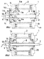
- the figure 1 represents an extrusion device 1 according to the invention, comprising a drive mechanism used to control an endless extruder screw 4, 5 having an axis of rotation A.
- the drive mechanism comprises a fixed casing 14 in which a torque motor is arranged with a stator 2 and a rotor 3.
- the stator 2 of cylindrical shape surrounds the rotor 3 of cylindrical shape.
- the stator and the rotor are centered on the axis of rotation A of the endless extrusion screw 4, 5.
- the extrusion device 1, the casing 14, and the motor elements 2, 3 respectively comprise an AV part.
- the front part AV being located on the side where the extrusion screw 4, 5 protrude out of the casing 14 to carry out the extrusion operation, and the rear part AR being situated on the side opposite to said extrusion screw 4, 5 .
- the extruder 1 comprises an endless extrusion screw 4, 5 which comprises a threaded extrusion portion 4 protruding from the front of the casing 14, and an extension 5 extending along the axis of the casing 14. the threaded portion 4 and intended to extend at least partially in the housing 14 to cooperate in rotation with the motor 2, 3.
- the diameter of the extension 5 is greater than or equal to the diameter of the threaded portion 4 of the extrusion screw.
- the extension 5 of the extrusion screw has at its free end a bore and a thread forming a threaded orifice 50, said threaded orifice 50 being intended to receive by screwing the threaded end 7a of an extraction tool 7 which will be described later.
- the extrusion device 1 also comprises a hollow shaft 8 coaxial with the rotor 3 and rotationally integral therewith.
- the hollow shaft 8 has an axial housing passing through said hollow shaft 8 from one side to the other, and which comprises two different portions 9, 10 visible in figure 4 .
- the first portion 9 is located at the front of the engine while the second portion 10 is partially covered by the engine.
- the diameter of the first portion 9 is smaller than the diameter of the second portion 10 so that said hollow shaft 8 has an inner shoulder 8a between said two portions 9, 10 of the axial housing.
- the first portion 9 of the axial housing of the hollow shaft 8 is intended to receive the extension 5 of the extrusion screw and the extrusion device comprises rotation locking means 12a, 12b of said extension 5 relative to said shaft hollow 8.
- the rotational locking means comprise on the one hand a groove 12a (visible in figure 4 ) in the first portion 9 of the axial housing of the hollow shaft 8, and secondly a protruding member 12b of the extension 5 of the extrusion screw, wherein said protruding member 12b is of complementary shape to the groove 12a in order to engage in the latter and rotationally block said extension 5 in said hollow shaft 8.
- the rotational locking means 12a, 12b are thus intended to make integral in rotation the extrusion screw 4, 5 and the hollow shaft 8.
- the blocking of the extrusion screw 4, 5 is located at the front of the drive mechanism and its housing 14.
- the protruding member 12b may be attached to the extension 5 of the extrusion screw or may be integral therewith.
- the rotational locking means 12 comprise at least one groove on the extension 5 of the extrusion screw and at least one obviously of complementary shape to the groove in the housing of the hollow shaft 8.
- the second portion 10 is intended to receive a removable axial support member 6 for locking the extrusion screw 4, 5 in translation.
- the extrusion device comprises means for blocking the removable axial support element 6 inside the hollow shaft 8, said locking means being intended to removably fasten said axial bearing element. 6 and said hollow shaft 8.
- the rotational locking means comprise on the one hand a thread 6a formed on the outer surface of the end of the axial bearing element 6 inserted in the hollow shaft 8, and on the other hand a tapping 10a made on the inner surface of the second portion 10 of the axial housing of the hollow shaft 8 in the vicinity of the shoulder 8a.
- the removable axial support element 6 is first introduced by the rear AR of the housing 14 and the motor into the second threaded portion 10 of the axial housing of the hollow shaft 8, and then screwed into said second portion 10 until bearing against the shoulder 8a.
- the fixing of the removable axial support element 6 in the hollow shaft 8 is thus achieved by screwing.
- the removable axial support element 6 represented on the Figures 1 and 2 is in the form of a tube centered around the axis of rotation A and protruding both at the front and at the rear of the engine 2, 3.
- the extrusion screw 4, 5 is introduced through the front end of the casing 14 and the motor 2, 3 into the first portion 9 of the axial housing of the hollow shaft. 8, until coming to take bearing against the axial bearing element 6 which is screwed into the second portion 10 of the axial housing presented by the hollow shaft 8.
- the extrusion screw 4, 5 can be inserted into the aforementioned housing by the front or rear end AR of the housing 14 and the motor 2, 3.
- the hollow shaft 8 has on its outer surface a rear portion 13a which partially surrounds the second portion 10 of the axial housing of the hollow shaft 8, and a front portion 13b which surrounds at least partly the first portion 9 of the axial housing of the hollow shaft 8 and a portion of said second portion 10.
- the rear portions 13a and 13b are separated by an outer shoulder 8b provided on the outer surface of the hollow shaft 8, wherein said outer shoulder 8 surrounds the second portion 10.
- the rear portion 13a has a diameter greater than the diameter of the front portion 13b.
- ball bearings 18 are disposed between the rear portion 13a of the hollow shaft 8 and a first bearing 14a of the housing 14 fixed.
- the bearings 18 are intended to allow the free rotation of the hollow shaft 8 realizing the housing 14, and therefore the free rotation of the extrusion screw 4, 5 relative to the housing 14 fixed.
- At least one rolling stopper 15 is disposed between the front portion 13b of the hollow shaft 8 and a second bearing 14b of the housing 14.
- the rolling stopper 15 comprises an under-roller stopper.
- the position of the rolling stopper 15 is situated in a plane formed by the zone of contact between the extension 5 of the extrusion screw and the removable axial bearing element 6, corresponding to the plane normal to the axis of rotation and passing through the inner shoulder 8a of the hollow shaft 8.
- the bearing abutment 15 abuts against the outer shoulder 8b of the hollow shaft 8, so that this bearing abutment 15 partly surrounds the first 9 and second 10 portions of the axial housing of the hollow shaft 8.
- the extrusion screw 4, 5 is held locked in translation along the axis of rotation A by bearing against the removable axial bearing element 6.
- the position of the rolling abutment around the contact zone allows a homogeneous distribution of the force during an extrusion operation.
- a holding plate 20 is positioned at the rear rear of the housing 14 and the motor perpendicular to the axis of rotation A and fixed to the casing 14.
- a removable cap 21 is fixed to the holding plate 20 by means of screws and nuts. The plug 21 is intended to close the rear AR of the casing 14.
- the disassembly and assembly of the extrusion screw 4, 5 can be operated by the rear AR of the housing 14 and the motor 2, 3.
- the plug 21 located on the retaining plate 20 at the rear engine is disassembled.
- an extraction tool 7 of the worm 4, 5 is used, wherein said extraction tool 7 is in the form of a rod, one end 7a has an external thread.
- This extraction tool 7 is introduced through its threaded end 7a into the axial bearing element 6 of tubular shape.
- the extraction tool 7 is attached to the extension 5 of the screw extrusion screw, said threaded end 7a cooperating with the threaded orifice 50.
- the tube 6 serving as removable axial support member is unscrewed from the second portion 10 of the axial housing of the hollow shaft 8, then pulled or pulled out of said axial housing of the hollow shaft 8 and out of the casing 14 of the device 1, in order to arrive at the configuration illustrated in FIG. figure 3 .
- traction is performed on the extraction tool 7 to pull the latter towards the rear AR of the device 1.
- the traction is performed using a threaded member 24 which is screwed on the rod 7, which more particularly has a thread over its entire length, and which bears on the holding plate 20.
- the threaded member 24 By driving the threaded member 24 in rotation when it is in contact with the holding plate 20, the rod 7 is driven by rearward translation of the AR of the device 1. This operation requires a clearance at the rear of the engine lower than in conventional extrusion devices.
- the attachment of the removable axial support member 6 in the hollow shaft 8 is by a bayonet system.
- the end of the axial bearing element 6 comporte then a protruding member.
- the protruding member is introduced into a complementary housing formed in the second portion 10 of the axial housing.
- the protruding member may also be located in the housing of the hollow shaft 8, and in this case the axial bearing element 6 comprises a housing of complementary shape to the projecting member. .
- the fixing of the removable axial support member 6 in the hollow shaft 8 is carried out by means of an expandable ring.
- the attachment of the removable axial support element 6 made by means of a clip or a circlip.
- the rotational locking means of the extension 5 in the hollow shaft 8 have a specific shape of the housing, such as a square shape or a triangle shape or a spline shape.
Landscapes
- Engineering & Computer Science (AREA)
- Mechanical Engineering (AREA)
- Extrusion Moulding Of Plastics Or The Like (AREA)
Applications Claiming Priority (1)
| Application Number | Priority Date | Filing Date | Title |
|---|---|---|---|
| FR0705229A FR2918921B1 (fr) | 2007-07-19 | 2007-07-19 | Dispositif d'extrusion a moteur couple |
Publications (2)
| Publication Number | Publication Date |
|---|---|
| EP2017063A2 true EP2017063A2 (de) | 2009-01-21 |
| EP2017063A3 EP2017063A3 (de) | 2013-05-22 |
Family
ID=39301404
Family Applications (1)
| Application Number | Title | Priority Date | Filing Date |
|---|---|---|---|
| EP08160482.9A Withdrawn EP2017063A3 (de) | 2007-07-19 | 2008-07-16 | Verdrängungsvorrichtung mit Drehmomentmotor |
Country Status (2)
| Country | Link |
|---|---|
| EP (1) | EP2017063A3 (de) |
| FR (1) | FR2918921B1 (de) |
Cited By (1)
| Publication number | Priority date | Publication date | Assignee | Title |
|---|---|---|---|---|
| EP2278690A1 (de) | 2009-07-24 | 2011-01-26 | SSD Parvex SAS | Einlageriger Motor |
Citations (4)
| Publication number | Priority date | Publication date | Assignee | Title |
|---|---|---|---|---|
| US6164811A (en) | 1999-06-16 | 2000-12-26 | Macro Engineering & Technology Inc. | Extruder assembly with improved screw removal capability |
| US20020064084A1 (en) | 2000-08-09 | 2002-05-30 | Reifenhauser Gmbh & Co. Maschinenfabrik | Coaxial extruder drive |
| DE10113644A1 (de) | 2001-03-21 | 2002-09-26 | Zahnradwerk Koellmann Gmbh | Stirnradgetriebe für Einschnecken-Extruder |
| EP1825027A2 (de) | 2004-11-18 | 2007-08-29 | Nederlandse Organisatie voor Toegepast-Natuuurwetenschappelijk Onderzoek TNO | Verfahren zur gewinnung von säuren |
Family Cites Families (2)
| Publication number | Priority date | Publication date | Assignee | Title |
|---|---|---|---|---|
| EP0777565A1 (de) * | 1994-08-31 | 1997-06-11 | Bühler AG | Extruder mit schneckenausbauvorrichtung |
| DE10357884A1 (de) * | 2003-12-11 | 2005-07-21 | Windmöller & Hölscher Kg | Direktangetriebener Extruder mit Adapter |
-
2007
- 2007-07-19 FR FR0705229A patent/FR2918921B1/fr not_active Expired - Fee Related
-
2008
- 2008-07-16 EP EP08160482.9A patent/EP2017063A3/de not_active Withdrawn
Patent Citations (4)
| Publication number | Priority date | Publication date | Assignee | Title |
|---|---|---|---|---|
| US6164811A (en) | 1999-06-16 | 2000-12-26 | Macro Engineering & Technology Inc. | Extruder assembly with improved screw removal capability |
| US20020064084A1 (en) | 2000-08-09 | 2002-05-30 | Reifenhauser Gmbh & Co. Maschinenfabrik | Coaxial extruder drive |
| DE10113644A1 (de) | 2001-03-21 | 2002-09-26 | Zahnradwerk Koellmann Gmbh | Stirnradgetriebe für Einschnecken-Extruder |
| EP1825027A2 (de) | 2004-11-18 | 2007-08-29 | Nederlandse Organisatie voor Toegepast-Natuuurwetenschappelijk Onderzoek TNO | Verfahren zur gewinnung von säuren |
Cited By (2)
| Publication number | Priority date | Publication date | Assignee | Title |
|---|---|---|---|---|
| EP2278690A1 (de) | 2009-07-24 | 2011-01-26 | SSD Parvex SAS | Einlageriger Motor |
| FR2948510A1 (fr) * | 2009-07-24 | 2011-01-28 | Ssd Parvex Sas | Moteur mono palier |
Also Published As
| Publication number | Publication date |
|---|---|
| FR2918921A1 (fr) | 2009-01-23 |
| FR2918921B1 (fr) | 2009-09-18 |
| EP2017063A3 (de) | 2013-05-22 |
Similar Documents
| Publication | Publication Date | Title |
|---|---|---|
| EP1961531B1 (de) | Befestigungsvorrichtung mit versenkbarem Handhebel und Geräte eine solche Vorrichtung enthaltend | |
| EP0793024B1 (de) | Verbindungs- und Verriegelungsvorrichtung für teleskopische Rohre | |
| EP2259901A2 (de) | Wiederverwendbare vorübergehende befestigungsvorrichtung zur vormontage von mindestens zwei vorab durchlochten bauteilen | |
| FR2919658A1 (fr) | Actionneur tubulaire pour l'entrainement d'un ecran domotique | |
| EP2285534B1 (de) | Werzeug zum anbringen von drahtgewindeeinsätzen mit verriegelungskeil und kit mit diesem werkzeug | |
| EP3999766B1 (de) | Kompakte und demontierbare fluidverbindung | |
| BE1010325A3 (fr) | Carottier. | |
| EP2498938A1 (de) | Gewindebohreinheit mit schutzvorrichtung | |
| EP2862676B1 (de) | Werkzeug zum Einbau eines Crimp-Elements | |
| EP1701823A1 (de) | Haltevorrichtung | |
| FR2493939A1 (fr) | Frein a disque | |
| FR2918921A1 (fr) | Dispositif d'extrusion a moteur couple | |
| EP1378385B1 (de) | Endstück für die Aufrollvorrichtung von Wickelgut wie Planen oder Ähnlichem, speziell für Kraftfahrzeuge | |
| FR2920104A1 (fr) | Mandrin porte-outil pour l'equipement d'une machine tournante | |
| EP0506932A1 (de) | Verfahren und vorrichtung zum einsetzen von einem o-ring in eine nut | |
| FR2969686B1 (fr) | Unite d'entrainement et de transmission, element fonctionnel et montage forme de cette unite et de l'element fonctionnel | |
| EP0471603A1 (de) | Verriegelungsvorrichtung eines Verbinders | |
| FR2806779A1 (fr) | Procede d'assemblage d'un conduit sur un embout tubulaire rigide au moyen d'un ecrou visse sur l'embout, et raccord pour la mise en oeuvre du procede | |
| FR3006217A1 (fr) | Adaptateur pour le demontage d'une goupille d'un systeme d'assemblage | |
| FR2921704A1 (fr) | Assemblage securise d'une premiere piece sur une deuxieme piece au moyen d'un organe de vissage | |
| FR3084272A1 (fr) | Dispositif pour la tenue d'une tige comprenant un troncon filete | |
| EP0336866A1 (de) | Trennbare Rohrkupplung | |
| FR2905426A1 (fr) | Dispositif hydraulique comprenant des moyens de fixation aptes a transmettre un couple eleve | |
| WO2021170941A1 (fr) | Moyen de demarrage comportant un capot de cle et vehicule equipe d'un tel moyen | |
| FR2727716A1 (fr) | Dispositif d'entrainement d'un pignon de commande notamment pour le deplacement d'un panneau coulissant |
Legal Events
| Date | Code | Title | Description |
|---|---|---|---|
| PUAI | Public reference made under article 153(3) epc to a published international application that has entered the european phase |
Free format text: ORIGINAL CODE: 0009012 |
|
| AK | Designated contracting states |
Kind code of ref document: A2 Designated state(s): AT BE BG CH CY CZ DE DK EE ES FI FR GB GR HR HU IE IS IT LI LT LU LV MC MT NL NO PL PT RO SE SI SK TR |
|
| AX | Request for extension of the european patent |
Extension state: AL BA MK RS |
|
| PUAL | Search report despatched |
Free format text: ORIGINAL CODE: 0009013 |
|
| AK | Designated contracting states |
Kind code of ref document: A3 Designated state(s): AT BE BG CH CY CZ DE DK EE ES FI FR GB GR HR HU IE IS IT LI LT LU LV MC MT NL NO PL PT RO SE SI SK TR |
|
| AX | Request for extension of the european patent |
Extension state: AL BA MK RS |
|
| RIC1 | Information provided on ipc code assigned before grant |
Ipc: B29C 47/08 20060101AFI20130416BHEP |
|
| 17P | Request for examination filed |
Effective date: 20131113 |
|
| RBV | Designated contracting states (corrected) |
Designated state(s): AT BE BG CH CY CZ DE DK EE ES FI FR GB GR HR HU IE IS IT LI LT LU LV MC MT NL NO PL PT RO SE SI SK TR |
|
| AKX | Designation fees paid |
Designated state(s): AT BE BG CH CY CZ DE DK EE ES FI FR GB GR HR HU IE IS IT LI LT LU LV MC MT NL NO PL PT RO SE SI SK TR |
|
| GRAP | Despatch of communication of intention to grant a patent |
Free format text: ORIGINAL CODE: EPIDOSNIGR1 |
|
| INTG | Intention to grant announced |
Effective date: 20180109 |
|
| STAA | Information on the status of an ep patent application or granted ep patent |
Free format text: STATUS: THE APPLICATION IS DEEMED TO BE WITHDRAWN |
|
| 18D | Application deemed to be withdrawn |
Effective date: 20180523 |