EP2017096A1 - Gleitschutzvorrichtung für Fahrzeugreifen, mit einem Tragegurt aus Bahnmaterial sowie Nachrüstsatz hierfür - Google Patents
Gleitschutzvorrichtung für Fahrzeugreifen, mit einem Tragegurt aus Bahnmaterial sowie Nachrüstsatz hierfür Download PDFInfo
- Publication number
- EP2017096A1 EP2017096A1 EP08011232A EP08011232A EP2017096A1 EP 2017096 A1 EP2017096 A1 EP 2017096A1 EP 08011232 A EP08011232 A EP 08011232A EP 08011232 A EP08011232 A EP 08011232A EP 2017096 A1 EP2017096 A1 EP 2017096A1
- Authority
- EP
- European Patent Office
- Prior art keywords
- tread
- skid device
- carrier belt
- traction
- traction means
- Prior art date
- Legal status (The legal status is an assumption and is not a legal conclusion. Google has not performed a legal analysis and makes no representation as to the accuracy of the status listed.)
- Granted
Links
- 239000000463 material Substances 0.000 title claims abstract description 22
- 239000004753 textile Substances 0.000 claims description 11
- 230000007704 transition Effects 0.000 claims description 4
- 230000009193 crawling Effects 0.000 abstract 1
- 238000005096 rolling process Methods 0.000 description 4
- 239000004744 fabric Substances 0.000 description 3
- 229910000831 Steel Inorganic materials 0.000 description 2
- 239000010959 steel Substances 0.000 description 2
- 229910000851 Alloy steel Inorganic materials 0.000 description 1
- 230000006978 adaptation Effects 0.000 description 1
- 239000011324 bead Substances 0.000 description 1
- 239000003795 chemical substances by application Substances 0.000 description 1
- 239000002184 metal Substances 0.000 description 1
- 239000007769 metal material Substances 0.000 description 1
- 239000000203 mixture Substances 0.000 description 1
- 230000004048 modification Effects 0.000 description 1
- 238000012986 modification Methods 0.000 description 1
- 239000004033 plastic Substances 0.000 description 1
- 229920003023 plastic Polymers 0.000 description 1
- 108090000623 proteins and genes Proteins 0.000 description 1
- 230000002787 reinforcement Effects 0.000 description 1
- 239000007787 solid Substances 0.000 description 1
Images


Classifications
-
- B—PERFORMING OPERATIONS; TRANSPORTING
- B60—VEHICLES IN GENERAL
- B60C—VEHICLE TYRES; TYRE INFLATION; TYRE CHANGING; CONNECTING VALVES TO INFLATABLE ELASTIC BODIES IN GENERAL; DEVICES OR ARRANGEMENTS RELATED TO TYRES
- B60C27/00—Non-skid devices temporarily attachable to resilient tyres or resiliently-tyred wheels
- B60C27/06—Non-skid devices temporarily attachable to resilient tyres or resiliently-tyred wheels extending over the complete circumference of the tread, e.g. made of chains or cables
- B60C27/16—Non-skid devices temporarily attachable to resilient tyres or resiliently-tyred wheels extending over the complete circumference of the tread, e.g. made of chains or cables formed of close material, e.g. leather or synthetic mats
- B60C27/18—Non-skid devices temporarily attachable to resilient tyres or resiliently-tyred wheels extending over the complete circumference of the tread, e.g. made of chains or cables formed of close material, e.g. leather or synthetic mats the material being fabric, e.g. woven wire or textile
-
- B—PERFORMING OPERATIONS; TRANSPORTING
- B60—VEHICLES IN GENERAL
- B60C—VEHICLE TYRES; TYRE INFLATION; TYRE CHANGING; CONNECTING VALVES TO INFLATABLE ELASTIC BODIES IN GENERAL; DEVICES OR ARRANGEMENTS RELATED TO TYRES
- B60C27/00—Non-skid devices temporarily attachable to resilient tyres or resiliently-tyred wheels
- B60C27/06—Non-skid devices temporarily attachable to resilient tyres or resiliently-tyred wheels extending over the complete circumference of the tread, e.g. made of chains or cables
Definitions
- the invention relates to an anti-skid device for vehicle tires, comprising a carrier belt made of a web material, wherein the carrier belt has an annular, radially outwardly facing running surface which extends in the axial direction along a lateral surface of a circular cylinder, and adjoins the two axial ends of the tread, Has in the radial direction of the tread inwardly extending side cheeks.
- the invention also relates to a retrofit kit for an anti-slip device for vehicle wheels, which has a textile belt with an annular, radially outwardly facing tread extending in the axial direction along a lateral surface of a circular cylinder, and in the axial direction of the tread subsequent to the Tread radially inwardly extending side cheeks comprises.
- Anti-slip devices of the type mentioned are, for example, from the US 2,682,907 , of the WO 2000/059745 A1 and the EP 1 621 370 A2 known.
- the tread is made of a fabric material that has good traction characteristics, especially on ice.
- the advantage of such textile anti-skid devices is their low weight and small size, in which they can be folded when not in use.
- a disadvantage of these anti-skid chains, however, is the traction on snow and mud as well as mud.
- the invention is therefore based on the object to improve the known anti-slip devices made of textile web material so that when still low weight and, when not in use, small size, the traction properties are improved.
- the traction means may be attached to the side cheeks.
- the attachment points at which the traction means are connected to the carrier belt not to lie between the tire and the ground during operation.
- both the attachment points and the tire material are spared.
- the tread absorbs the centrifugal forces as tensile forces.
- the traction means are attached to or as close as possible to the tread, so that the centrifugal forces generated by the traction means when rolling also as directly as possible the tread be initiated.
- the traction means in a transition region of the side cheeks to the tread preferably so be secured in the adjacent to the tread portion of the side cheeks.
- the side cheeks remain virtually free of force in this embodiment, so that they can be configured elastically beaubar at its radially inner edge, for example, for the purpose of easier assembly. A stiffening of the side cheeks is not necessary. The closer the attachment points are to the tread, the fewer forces the side cheeks must receive.
- the traction means may extend at least in sections in the axial direction from one axial to the other axial edge of the tread, so that the centrifugal forces generated by the traction means are introduced on both sides of the tread.
- the fastening means are preferably in the axial direction at the same height and / or are arranged symmetrically on the running surface and / or the two side cheeks, so Centrifugal forces at the same circumferential positions introduced into the tread and no shear or torsional forces are generated in the carrier belt.
- the traction means are repeatedly releasably, preferably individually detachably secured to the carrier belt, since in this way an optimal adaptation of the antiskid device to the respective road conditions is possible by replacing the traction means.
- the traction means can be changed when worn.
- the fastening means used to fasten the traction means on the carrier belt do not hit the ground during operation and are damaged
- the fastening means may preferably be arranged within the outer contour of the tread so that they do not come into contact with the ground on which the tire unrolls ,
- a high load capacity of the carrier belt can be achieved if it is made of a textile material substantially seamless.
- the textile material can also form only an upper layer of the flexible Sugurts.
- a textile material has high friction values, especially on ice.
- the traction means are formed at least partially in the form of axially extending, circumferentially spaced chain strands, because in this way the traction obtained by the chain strands is greatest.
- the tread can touch the ground in the spaces between the chain strands so that good traction values can be achieved even with ice.
- the chain strands can in particular run parallel to one another.
- the distance between the chain strands in the circumferential direction is at most about 10% greater than the circumferentially measured length of the support surface of the vehicle tire. Preferably, however, the distance is less than the length of the support surface, so that always a traction agent has contact with the ground.
- chain elements are low temperature resistant materials, especially steel alloys, but also plastics in question. Chain elements of different shape and composition can be combined in a chain strand.
- the retrofit kit has traction elements with chain links and with the traction elements connectable by hand on the tread and / or the side cheeks attachable fastener.
- the fastening means are preferably attachable without special tools on the side cheeks.
- the known textile anti-slip devices can be easily retrofitted. They can be used either in their original design or together with the traction means and thus adapted to the ground when, according to a further advantageous embodiment of the retrofit kit, the traction elements are repeatedly designed releasably by the fastening means.
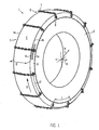
- Fig. 1 the anti-skid device 1 is shown mounted on a vehicle tire 2.
- the anti-skid device 1 has a flexible running belt 3 of a web material, preferably of a textile material, such as a fabric or a non-woven, which rests in the mounted state on a tread of the tire and this engages laterally.
- the carrier belt 3 is provided with a running surface 4, which extends in the axial direction A approximately over the tire width and is designed as a lateral surface of a circular cylinder.
- the tread 4 has in the radial direction R to the outside, so that they on an in Fig. 1 not shown, on which the vehicle tire 2 rolls, comes to rest.
- ends 4a, 4b of the tread 4 are each provided by the running surface 4 in the radial direction inwardly extending, annular side walls 5, of which in Fig. 1 only the one side cheek is visible.
- the side cheeks 5 can in particular be seamlessly connected to the tread 4.
- a circumferential reinforcement 5a in the form of a bead or a sewn-in traction means, such as a rope, may be attached.
- the side cheeks 5 may also be preferably designed to be elastically extensible in the radial direction, for example to be made of an elastically extensible material.
- Traction elements 6 are attached to the carrier belt 3, which have chain elements 7, on the outside of the running surface 4.
- the traction means 6 are preferably repeatedly releasably attached to the carrier belt 3 on the running surface 4 or on the side cheeks 5 as close as possible to the running surface 4, for example in a cross-hatched transition region 9, in which the side cheek 5 adjoins the running surface 4.
- the traction means 6 extend in the axial direction parallel to each other from side cheek to side cheek.
- the traction means 6 are further spaced apart in the circumferential direction U, wherein the distance D in the circumferential direction U between adjacent traction means 6 in about the Length L of the bearing surface of the vehicle tire 2 in the circumferential direction U corresponds, but preferably smaller than the length L is.
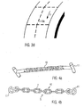
- the traction means 6 may be in particular chain strands of a round steel chain, as in Fig. 4b are shown in detail.
- the length S of the chain strand 10 is preferably at least about as large as the width B of the vehicle tire 2.
- At the ends of the chain strand repeatedly releasable retaining means 11 are hooked in the form of karabines in the chain strand 10 or otherwise preferably hinged.
- chain elements of different shape, for example with tabs, in the form of webs or rings, including in any combination. Edged chain elements, such as tabs or bars, lead to good traction, especially on ice.
- a modification is shown in which the holding means 11 are formed in otherwise unchanged chain strand 10 in the form of T-shaped gags, which may also be suspended in the chain strand 10.
- the holding means 11 and the chain strand 10 are hinged together, so that the traction means 6 can follow the cross-sectional contour of the tire on the tread and the side cheeks and the flexing movement of the tire 2 when rolling on the ground.
- the holding means 11 is in the in Fig. 4a and 4b shown embodiment releasably formed by the fastener 8.
- Fig. 2a to 2d schematically a portion of a side cheek 5 of the anti-skid device 1 is shown.
- Fig. 2a are the fasteners 8 configured in the form of eyelets 12 which form through the side wall 5 reaching openings and in the holding means 6, for example, the gag or carabiners of Fig. 4a and 4b can be hung.
- the eyelets 12 are surrounded by a reinforced edge, in particular made of a metal.
- eyelets and tabs 14 may be provided as fasteners 8.
- the tabs 8 also allow the use of, for example, carabiners as holding means 11.
- the tabs 14 may be formed by two preferably radius-parallel slots 15 in the side cheek 5 and reinforced at their edges.
- the tabs 8 may also be formed by a material bridge extending from the transition region 9 to, preferably, the edge 5a of the side cheek 5, which extends over the side cheek 5. Such a material bridge may be woven into the fabric material of the carrier belt 3.
- the attachment means 8 may further be in the form of an eye 16, the attachment body 17 of which extends through the side cheek 5, for example in the form of a rivet, as in FIG Fig. 2c is shown.
- the holding means 11 can be inserted releasably, for example, latched, be.
- a flap 14 opening in the radial direction R can also be provided, as shown in FIG Fig. 2d is shown.
- the tab 14 may be formed in particular of a metal material and riveted at its edges to the material of the side cheek 5 or glued to it, welded or sewn.
- the anti-skid device 1 is designed as a retrofit kit, then it comprises at least the traction elements 6 and the attachment means 8.
- the attachment means 8 are designed such that they can be attached to the side cheeks 5 preferably by hand, preferably without special tools. This is for example in the fasteners 8 of Fig. 2a, 2c and 2d This is because equipment for setting eyelets and rivets in textile materials can be operated with common household tools such as a hammer and a solid base. The tool can also be part of the retrofit kit.
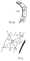
- Fig. 3a can be provided between two parallel chain strands 10a, 10b at least one with respect to the circumferential direction U obliquely extending chain portion 10c, 10d.
- a track cross be formed in the middle of the tread 4 cross-chain strands 10c and 10d.
- a ring 18 is arranged, on which the chain strands run diagonally over the running surface are suspended.
- the oblique chain strand sections 10c, 10d may also be connected by at least one chain strand section 10e extending in the circumferential direction U, preferably parallel to this. In this embodiment, running in the circumferential direction U chain strand 10e ensures good directional stability.
- Fig. 1 illustrated arrangement of the traction means 6 are supplemented by at least one chain strand 10e, which extends in the circumferential direction U around the tread 4 around, connects the axis-parallel chain strands and ensures good straight-line stability.
- the distance between the traction means is so large that the tread 4 touches the ground in a hard, substantially unyielding reason due to the flexibility of the vehicle tire 2 and additionally increases the traction.
Landscapes
- Engineering & Computer Science (AREA)
- Mechanical Engineering (AREA)
- Textile Engineering (AREA)
- Tires In General (AREA)
- Buckles (AREA)
- Belt Conveyors (AREA)
- Wrappers (AREA)
Abstract
Description
- Die Erfindung betrifft eine Gleitschutzvorrichtung für Fahrzeugreifen, mit einem Trägergurt aus einem Bahnmaterial, wobei der Trägergurt eine kreisringförmige, radial nach außen weisende Lauffläche, die sich in axialer Richtung entlang einer Mantelfläche eines Kreiszylinders erstreckt, und sich an die beiden axialen Enden der Lauffläche anschließende, sich in radialer Richtung von der Lauffläche nach innen erstreckende Seitenwangen aufweist. Die Erfindung betrifft zudem einen Nachrüstsatz für eine Gleitschutzvorrichtung für Fahrzeugräder, die einen Textilgurt mit einer kreisringförmigen, radial nach aussenden weisenden Lauffläche, die sich in axialer Richtung entlang einer Mantelfläche eines Kreiszylinders erstreckt, und sich in axialer Richtung an die Lauffläche anschließende, sich von der Lauffläche radial nach innen erstreckende Seitenwangen umfasst.
- Gleitschutzvorrichtungen der eingangs genannten Art sind beispielsweise aus der
US 2,682,907 , derWO 2000/059745 A1 und derEP 1 621 370 A2 bekannt. Bei diesen Gleitschutzvorrichtungen ist die Lauffläche aus einem Gewebematerial gefertigt, das besonders auf Eis gute Traktionseigenschaften aufweist. Der Vorteil solcher textiler Gleitschutzvorrichtungen liegt in ihrem geringen Gewicht und ihrer geringen Größe, in die sie bei Nichtgebrauch gefaltet werden können. Nachteilig bei diesen Gleitschutzketten ist allerdings das Traktionsverhalten auf Schnee und Matsch sowie Schlamm. - Der Erfindung liegt daher die Aufgabe zugrunde, die bekannten Gleitschutzvorrichtungen aus textilem Bahnmaterial so zu verbessern, dass bei nach wie vor geringem Gewicht und, bei Nichtgebrauch, geringer Größe die Traktionseigenschaften verbessert werden.
- Diese Aufgabe wird erfindungsgemäß für die eingangs genannte Gleitschutzvorrichtung auf einfache Weise dadurch gelöst, dass vom Trägergurt an der Lauffläche anlegbar gehaltene Traktionsmittel in Form von Kettenelementen vorgesehen sind.
- Diese Lösung hat den Vorteil, dass insbesondere die Traktion auf Schnee und Matsch sowie in Schlamm verbessert wird. Gleichzeitig bleiben die guten Lenk- und Traktionseigenschaften auf Eis aufgrund der nach wie vor vorhandenen Lauffläche aus Bahnmaterial erhaften. Durch die Verwendung von Kettenelementen bleibt die Flexibilität des Bahnmaterials nutzbar, so dass die Gleitschutzvorrichtung nach wie vor auf eine kleine Größe zusammengelegt werden kann, wenn sie nicht gebraucht wird. Als Kettenelemente können neben Rundstahlkettengliedem auch Kettenlaschen oder stegförmige, sich im Betrieb aufstellende Elemente oder beliebige Kombinationen hiervon verwendet werden. Die Kettenelemente sind - wie bei Ketten üblich - gelenkig miteinander verbunden.
- Die erfindungsgemäße Lösung kann durch weitere, jeweils für sich unabhängig vorteilhafte und beliebig miteinander kombinierbare Ausgestaltungen weiter verbessert werden.
- In einer weiteren vorteilhaften Ausgestaltung können die Traktionsmittel an den Seitenwangen befestigt sein. Bei dieser Ausgestaltung kommen die Befestigungspunkte, an denen die Traktionsmittel mit dem Trägergurt verbunden sind, im Betrieb nicht zwischen Reifen und Untergrund zu liegen. Dadurch werden sowohl die Befestigungspunkte als auch das Reifenmaterial geschont. Im Betrieb, bei abrollendem Reifen, nimmt die Lauffläche die Zentrifugalkräfte als Zugkräfte auf.Von besonderem Vorteil ist es daher, wenn die Traktionsmittel an oder möglichst nahe an der Lauffläche befestigt sind, so dass die von den Traktionsmitteln beim Abrollen erzeugten Zentrifugalkräfte ebenfalls möglichst direkt in die Lauffläche eingeleitet werden. Beispielsweise können die Traktionsmittel in einem Übergangsbereich der Seitenwangen zur Lauffläche, vorzugsweise also in dem an die Lauffläche angrenzenden Abschnitt der Seitenwangen befestigt sein. Die Seitenwangen bleiben bei dieser Ausgestaltung nahezu kraftfrei, so dass sie an ihrem radial innenliegenden Rand beispielsweise zum Zwecke einer leichteren Montage elastisch weitbar ausgestaltet sein können. Eine Versteifung der Seitenwangen ist somit nicht notwendig. Je näher die Befestigungspunkte zur Lauffläche hin angeordnet sind, umso weniger Kräfte müssen die Seitenwangen aufnehmen.
- Dieser Vorteil wird natürlich auch erreicht, wenn die Traktionsmittel direkt an der Lauffläche angebracht sind. Allerdings werden dann die Stellen, an denen die Traktionsmittel befestigt sind, durch das Abrollen stärker belastet.
- Die Traktionsmittel können sich in einer weiteren Ausgestaltung zumindest abschnittsweise in axialer Richtung von dem einen axialen zu dem anderen axialen Rand der Lauffläche erstrecken, so dass die von den Traktionsmitteln erzeugten Zentrifugalkräfte an beiden Seiten der Lauffläche eingeleitet werden.
- Die Befestigungsmittel liegen bevorzugt in axialer Richtung auf gleicher Höhe und/oder sind symmetrisch an der Lauffläche und/oder den beiden Seitenwangen angeordnet, damit Zentrifugalkräfte an gleichen Umfangspositionen in die Lauffläche eingeleitet und keine Scher- bzw. Torsionskräfte im Trägergurt erzeugt werden.
- Von Vorteil ist ferner, wenn die Traktionsmittel wiederholt lösbar, bevorzugt einzeln lösbar, am Trägergurt befestigt sind, da auf diese Weise durch einen Austausch der Traktionsmittel eine optimale Anpassung der Gleitschutzvorrichtung an die jeweiligen Straßenverhältnisse möglich ist. Außerdem können die Traktionsmittel bei Verschleiß gewechselt werden.
- Damit die zur Befestigung der Traktionsmittel am Trägergurt dienenden Befestigungsmittel im Betrieb nicht auf dem Untergrund aufschlagen und beschädigt werden, können die Befestigungsmittel vorzugsweise innerhalb der Außenkontur der Lauffläche angeordnet sein, so dass sie nicht mit dem Untergrund, auf dem der Reifen abrollt, in Berührung kommen.
- Eine hohe Belastbarkeit des Trägergurtes kann erreicht werden, wenn dieser aus einem textilen Material im Wesentlichen nahtfrei gefertigt ist. Dabei kann das textile Material auch lediglich eine obere Schicht des flexiblen Trägergurts bilden. Ein textiles Material hat besonders auf Eis hohe Reibungswerte.
- Es ist ferner von Vorteil, wenn die Traktionsmittel wenigstens abschnittsweise in Form von axial verlaufenden, in Umfangsrichtung voneinander beabstandeten Kettensträngen ausgebildet sind, weil auf diese Weise die durch die Kettenstränge erhaltene Traktion am größten ist. Gleichzeitig kann in den Zwischenräumen zwischen den Kettensträngen die Lauffläche den Untergrund berühren, so dass auch bei Eis gute Traktionswerte erzielt werden. Die Kettenstränge können insbesondere parallel zueinander verlaufen.
- Um ein Durchrutschen der Reifen auf weichem Untergrund weitgehend zu vermeiden, ist es ferner von Vorteil, wenn der Abstand der Kettenstränge voneinander in Umfangsrichtung höchstens etwa um 10 % größer ist als die in Umfangsrichtung gemessene Länge der Auflagefläche des Fahrzeugreifens. Vorzugsweise ist der Abstand jedoch geringer als die Länge der Auflagefläche, damit stets ein Traktionsmittel Kontakt mit dem Untergrund hat.
- Als Material für die Kettenelemente kommen tieftemperaturfeste Werkstoffe, insbesondere Stahliegierungen, aber auch Kunststoffe in Frage. Kettenelemente unterschiedlicher Form und Zusammensetzung können in einem Kettenstrang kombiniert werden.
- Die eingangs genannte Aufgabe wird schließlich auch gelöst durch einen Nachrüstsatz für eine bekannte Gleitschutzvorrichtung aus einem textilen Gurt mit einer kreisringförmigen, radial nach außen weisenden Lauffläche, die sich in axialer Richtung entlang einer Mantelfläche eines Kreiszylinders erstreckt, und sich in axialer Richtung an die Lauffläche anschließende, sich von der Lauffläche radial nach innen erstreckende Seitenwangen aufweist. Der Nachrüstsatz weist Traktionselemente mit Kettengliedern und mit den Traktionselementen verbindbare, von Hand an der Lauffläche und/oder den Seitenwangen befestigbare Befestigungsmittel auf. Die Befestigungsmittel sind vorzugsweise ohne Spezialwerkzeug an den Seitenwangen befestigbar.
- Auf diese Weise können die bekannten textilen Gleitschutzvorrichtungen leicht nachgerüstet werden. Sie können wahlweise in ihrer ursprünglichen Ausgestaltung oder zusammen mit den Traktionsmitteln verwendet und damit an den Untergrund angepasst werden, wenn gemäß einer weiteren vorteilhaften Ausgestaltung des Nachrüstsatzes die Traktionselemente wiederholt lösbar von den Befestigungsmitteln ausgestaltet sind.
- Im Folgenden ist die Erfindung mit Bezug auf die Zeichnungen anhand mehrerer Ausführungsformen, deren unterschiedliche Merkmale gemäß den obigen Bemerkungen beliebig miteinander kombinierbar sind, näher ertäutert.
- Es zeigen:
- Fig. 1
- eine schematische Perspektivdarstellung einer erfindungsgemäßen Gleitschutzvorrichtung sowie einen erfindungsgemäßen Nachrüstsatz;
- Fig. 2a bis 2d
- verschiedene Ausführungsformen von Befestigungsmitteln der erfin- dungsgemäßen Gleitschutzvorrichtung in schematischen Darstellun- gen;
- Fig. 3a bis 3d
- verschiedene Ausführungsformen von Traktionsmitteln in schemati- schen Darstellungen;
- Fig. 4a, 4b
- zwei unterschiedliche Ausführungsformen von Traktionsmitteln in schematischer Darstellung.
- Zunächst wird der Aufbau einer erfindungsgemäßen Gleitschutzvorrichtung sowie eines erfindungsgemäßen Nachrüstsatzes anhand der
Fig. 1 erläutert. - In
Fig. 1 ist die Gleitschutzvorrichtung 1 auf einem Fahrzeugreifen 2 montiert dargestellt. Die Gleitschutzvorrichtung 1 weist einen flexiblen Laufgurt 3 aus einem Bahnmaterial, vorzugsweise aus einem textilen Material, wie einem Gewebe oder einem Vlies, auf, der im montierten Zustand auf einer Lauffläche des Reifens aufliegt und diese seitlich umgreift. Hierzu ist der Trägergurt 3 mit einer Lauffläche 4 versehen, die sich in axialer Richtung A in etwa über die Reifenbreite erstreckt und als Mantelfläche eines Kreiszylinders ausgestaltet ist. Die Lauffläche 4 weist dabei in radialer Richtung R nach außen, so dass sie auf einem inFig. 1 nicht dargestellten Untergrund, auf dem der Fahrzeugreifen 2 abrollt, zu liegen kommt. - An den beiden in axialer Richtung A gelegenen Enden 4a, 4b der Lauffläche 4 sind jeweils sich von der Lauffläche 4 in radialer Richtung nach innen erstreckende, kreisringförmige Seitenwangen 5 vorgesehen, von denen in
Fig. 1 nur die eine Seitenwange zu sehen ist. Die Seitenwangen 5 können insbesondere nahtfrei mit der Lauffläche 4 verbunden sein. An dem radial inneren Ende der Seitenwange 5 kann eine umlaufende Verstärkung 5a in Form eines Wulstes oder eines eingenähten Zugmittels, wie einem Seil, angebracht sein. Die Seitenwangen 5 können auch in radialer Richtung vorzugsweise elastisch weitbar ausgestaltet sein, beispielsweise aus einem elastisch dehnbaren Material gefertigt sein. - An der Lauffläche 4 außen anliegend sind Traktionselemente 6 am Trägergurt 3 befestigt, die Kettenelemente 7 aufweisen.
- Die Traktionsmittel 6 sind über Befestigungsmittel 8 vorzugsweise wiederholt lösbar am Trägergurt 3 an der Lauffläche 4 oder an den Seitenwangen 5 möglichst nahe an der Lauffläche 4, beispielsweise in einem schraffiert angedeuteten Übergangsbereich 9, in dem die Seitenwange 5 an die Lauffläche 4 angrenzt, angebracht.
- Wie in der in
Fig. 1 dargestellten Ausführungsform zu erkennen ist, verlaufen die Traktionsmittel 6 in axialer Richtung parallel zueinander von Seitenwange zu Seitenwange. Die Traktionsmittel 6 sind ferner in Umfangsrichtung U voneinander beabstandet, wobei der Abstand D in Umfangsrichtung U zwischen benachbarten Traktionsmitteln 6 in etwa der Länge L der Auflagefläche des Fahrzeugreifens 2 in Umfangsrichtung U entspricht, vorzugsweise jedoch kleiner als die Länge L ist. - Die Traktionsmittel 6 können insbesondere Kettenstränge aus einer Rundstahlkette sein, wie sie in
Fig. 4b im Detail dargestellt sind. Die Länge S des Kettenstranges 10 ist vorzugsweise wenigstens etwa so groß wie die Breite B des Fahrzeugreifens 2. An den Enden des Kettenstrangs sind wiederholt lösbare Haltemittel 11 in Form von Karabinem in den Kettenstrang 10 eingehängt oder anderweitig vorzugsweise gelenkig befestigt. - Anstelle von oder zusätzlich zu Rundstahlketten können auch Traktionselemente verwendet werden, die Kettenelemente unterschiedlicher Form, beispielsweise mit Laschen, in Form von Stegen oder Ringen, auch in beliebiger Kombination umfassen. Kantige Kettenelemente, wie Laschen oder Stege, führen insbesondere auf Eis zu guter Traktion.
- In
Fig. 4a ist eine Abwandlung gezeigt, bei der die Haltemittel 11 bei ansonsten unverändertem Kettenstrang 10 in Form von T-förmigen Knebeln ausgebildet sind, die ebenfalls in den Kettenstrang 10 eingehängt sein können. Bevorzugt sind das Haltemittel 11 und der Kettenstrang 10 gelenkig miteinander verbunden, so dass das Traktionsmittel 6 der Querschnittskontur des Reifens über die Lauffläche und die Seitenwangen und auch der Walkbewegung des Reifens 2 beim Abrollen auf dem Untergrund folgen kann. Das Haltemittel 11 ist in der inFig. 4a und 4b gezeigten Ausgestaltung wiederholt lösbar vom Befestigungsmittel 8 ausgebildet. - Für die Ausgestaltung des Befestigungsmittels 8 sind ebenfalls mehrere Ausführungsformen möglich, wie im Folgenden mit Bezug auf die
Fig. 2a bis 2d beispielhaft ausgeführt ist. In denFig. 2a bis 2d ist schematisch ein Abschnitt einer Seitenwange 5 der Gleitschutzvorrichtung 1 dargestellt. - In der
Fig. 2a sind die Befestigungsmittel 8 in Form von Ösen 12 ausgestaltet, die durch die Seitenwange 5 reichende Öffnungen ausbilden und in die die Haltemittel 6 beispielsweise die Knebel oder Karabiner derFig. 4a und 4b eingehängt werden können. Die Ösen 12 sind mit einem verstärkten Rand insbesondere aus einem Metall umgeben. - Anstelle von Ösen können auch Laschen 14 als Befestigungselemente 8 vorgesehen sein. Die Laschen 8 erlauben ebenfalls die Verwendung von beispielsweise Karabinern als Haltemittel 11.
- Die Laschen 14 können durch zwei vorzugsweise radiusparallele Schlitze 15 in der Seitenwange 5 gebildet und an ihren Rändern verstärkt sein. Alternativ können die Laschen 8 auch durch eine sich von dem Übergangsbereich 9 bis vorzugsweise dem Rand 5a der Seitenwange 5 erstreckende Materialbrücke gebildet sein, die sich über die Seitenwange 5 erstreckt. Eine derartige Materialbrücke kann in das Gewebematerial des Trägergurtes 3 eingewebt sein.
- Das Befestigungsmittel 8 kann ferner in Form eines Auges 16 ausgebildet sein, dessen Befestigungskörper 17 sich durch die Seitenwange 5 hindurch erstreckt, beispielsweise in Form eines Nietes, wie in
Fig. 2c gezeigt ist. In das Auge 16 kann das Haltemittel 11 lösbar eingesetzt, beispielsweise eingeklinkt, werden. - Anstelle einer sich in Umfangsrichtung U öffnenden Lasche 14, wie sie in
Fig. 2b gezeigt ist, kann auch eine sich in radialer Richtung R öffnende Lasche 14 vorgesehen sein, wie sie inFig. 2d gezeigt ist. Die Lasche 14 kann insbesondere aus einem Metallwerkstoff gebildet sein und an ihren Rändern an das Material der Seitenwange 5 genietet oder mit diesem verklebt, verschweißt oder vernäht sein. - Ist die Gleitschutzvorrichtung 1 als Nachrüstsatz ausgebildet, so umfasst dieser wenigstens die Traktionselemente 6 und die Befestigungsmittel 8. Die Befestigungsmittel 8 sind dabei so ausgestaltet, dass sie von Hand vorzugsweise ohne Spezialwerkzeug an den Seitenwangen 5 angebracht werden können. Dies ist beispielsweise bei den Befestigungsmitteln 8 der
Fig. 2a, 2c und2d der Fall, da Geräte zum Setzen von Ösen und Nieten in textilen Materialien mit haushaltsüblichen Werkzeugen, wie einem Hammer und einer festen Unterlage, bedient werden können. Das Werkzeug kann auch Teil des Nachrüstsatzes sein. - In den
Fig. 3a bis 3d sind Abwandlungen der Traktionsmittel 6 schematisch dargestellt. - Gemäß der Ausführungsform der
Fig. 3a kann zwischen zwei parallelen Kettensträngen 10a, 10b wenigstens ein bezüglich der Umfangsrichtung U schräg verlaufender Kettenabschnitt 10c, 10d vorgesehen sein. Insbesondere kann, wie inFig. 3a dargestellt, ein Spurkreuz von sich in der Mitte der Lauffläche 4 überkreuzenden Kettensträngen 10c und 10d gebildet sein. Im Bereich der Überkreuzung ist ein Ring 18 angeordnet, an dem die diagonal über die Lauffläche verlaufenden Kettenstränge eingehängt sind. - Anstelle des Ringes 18 können die schräg verlaufenden Kettenstrangabschnitte 10c, 10d auch durch wenigstens einen in Umfangsrichtung U, vorzugsweise parallel zu dieser, verlaufenden Kettenstrangabschnitt 10e verbunden sein. Bei dieser Ausgestaltung sorgt der in Umfangsrichtung U verlaufende Kettenstrang 10e für einen guten Geradeauslauf.
- Ein relativ unkomplizierter Aufbau mit einer geringen Anzahl von Teilen ergibt sich bei der in der
Fig. 3c dargestellten Ausgestaltung, bei der als Traktionsmittel 6 ein einzelner Kettenstrang 10 zickzackförmig um den gesamten Umfang des Fahrzeugreifens 2 abwechselnd durch die Befestigungsmittel 8 jeweils einer Seitenwange 5 gehalten ist. - Schließlich kann die in
Fig. 1 dargestellte Anordnung der Traktionsmittel 6 durch wenigstens einen Kettenstrang 10e ergänzt werden, der in Umfangsrichtung U um die Lauffläche 4 herum verläuft, die achsparallelen Kettenstränge verbindet und für einen guten Geradeauslauf sorgt. - Bei allen Ausführungsformen der
Fig.3a bis 3d ist der Abstand zwischen den Traktionsmitteln so groß, dass die Lauffläche 4 bei hartem, im Wesentlichen unnachgiebigem Grund aufgrund der Flexibilität des Fahrzeugreifens 2 den Untergrund berührt und zusätzlich die Traktion erhöht.
Claims (12)
- Gleitschutzvorrichtung (1) für Fahrzeugreifen (2) mit einem flexiblen Trägergurt (3) aus einem Bahnmaterial, wobei der Trägergurt eine kreisringförmige, radial nach außen weisende Lauffläche (4), die sich in axialer Richtung (A) entlang einer Mantelfläche eines Kreiszylinders erstreckt, und sich an die beiden axialen Enden (4a, 4b) der Lauffläche anschließende, sich in radialer Richtung (R) von der Lauffläche nach innen erstreckende Seitenwangen (5) aufweist, gekennzeichnet durch vom Trägergurt (3) auf der Lauffläche (4) anlegbar gehaltene Traktionsmittel (6) in Form von Kettenelementen (7).
- Gleitschutzvorrichtung (1) nach Anspruch 1, dadurch gekennzeichnet, dass die Traktionsmittel (6) an den Seitenwangen (5) und/oder der Lauffläche (4) befestigt sind.
- Gleitschutzvorrichtung (1) nach Anspruch 2, dadurch gekennzeichnet, dass die Traktionsmittel (6) in einem Übergangsbereich (9) der Seitenwangen zur Lauffläche (4) befestigt sind.
- Gleitschutzvorrichtung (1) nach einem der Ansprüche 1 bis 3, dadurch gekennzeichnet, dass sich die Traktionsmittel (6) zumindest abschnittsweise in axialer Richtung (A) von der einen zur anderen Seitenwange (5) erstrecken.
- Gleitschutzvorrichtung (1) nach einem der Ansprüche 1 bis 3, dadurch gekennzeichnet, dass die Traktionsmittel (6) wiederholt lösbar an dem Trägergurt (3) befestigt sind.
- Gleitschutzvorrichtung (1) nach einem der Ansprüche 1 bis 5, dadurch gekennzeichnet, dass die Traktionsmittel (6) an am Trägergurt (3) angebrachten Befestigungsmitteln (8) befestigt sind und die Befestigungsmittel (8) innerhalb der Außenkontur der Lauffläche (4) angeordnet sind.
- Gleitschutzvorrichtung (1) nach einem der Ansprüche 1 bis 6, dadurch gekennzeichnet, dass die Seitenwangen 5 und die Lauffläche 4 im Wesentlichen nahtfrei miteinander verbunden sind.
- Gleitschutzvorrichtung (1) nach einem der Ansprüche 1 bis 7, dadurch gekennzeichnet, dass die Traktionsmittel 6 axial verlaufende, in Umfangsrichtung voneinander beabstandete Kettenstränge aufweisen, die parallel zueinander verlaufen.
- Gleitschutzvorrichtung (1) nach Anspruch 8, dadurch gekennzeichnet, dass der Abstand (D) der axial verlaufenden Kettenstränge (10) in Umfangsrichtung in etwa einer Länge (L) der Auflagefläche des Fahrzeugreifens (2) auf dem Untergrund entspricht.
- Nachrüstsatz für eine Gleitschutzvorrichtung (1) für Fahrzeugreifen (2), die einen textilen Gurt (3) mit einer kreisringförmigen, radial nach außen weisenden Lauffläche (4), die sich in axialer Richtung entlang einer Mantelfläche eines Kreiszylinders erstreckt, und sich in axialer Richtung an die Laufflächen anschließende, sich von der Lauffläche radial nach innen erstreckende Seitenwangen (5) aufweist, wobei der Nachrüstsatz Traktionselemente (6) mit Kettengliedern (7) und mit den Traktionselementen verbindbare, von Hand an den Seitenwangen (5) befestigbare Befestigungsmittel (8) aufweist.
- Nachrüstsatz nach Anspruch 10, dadurch gekennzeichnet, dass die Traktionselemente (6) wiederholt lösbar von den Befestigungsmitteln (8) ausgestaltet sind.
- Nachrüstsatz nach Anspruch 10 oder 11, dadurch gekennzeichnet, dass die Befestigungsmittel in Form von handsetzbarer Ösen oder Nieten ausgebildet sind.
Priority Applications (1)
| Application Number | Priority Date | Filing Date | Title |
|---|---|---|---|
| PL08011232T PL2017096T3 (pl) | 2007-07-18 | 2008-06-20 | Urządzenie przeciwpoślizgowe do opon pojazdu, z pasem nośnym z materiału pasmowego oraz zestaw modernizacyjny do niego |
Applications Claiming Priority (1)
| Application Number | Priority Date | Filing Date | Title |
|---|---|---|---|
| DE202007010095U DE202007010095U1 (de) | 2007-07-18 | 2007-07-18 | Gleitschutzvorrichtung für Fahrzeugreifen, mit einem Tragegurt aus Bahnmaterial sowie Nachrüstsatz hierfür |
Publications (2)
| Publication Number | Publication Date |
|---|---|
| EP2017096A1 true EP2017096A1 (de) | 2009-01-21 |
| EP2017096B1 EP2017096B1 (de) | 2009-11-18 |
Family
ID=39682600
Family Applications (1)
| Application Number | Title | Priority Date | Filing Date |
|---|---|---|---|
| EP08011232A Not-in-force EP2017096B1 (de) | 2007-07-18 | 2008-06-20 | Gleitschutzvorrichtung für Fahrzeugreifen, mit einem Tragegurt aus Bahnmaterial sowie Nachrüstsatz hierfür |
Country Status (5)
| Country | Link |
|---|---|
| EP (1) | EP2017096B1 (de) |
| AT (1) | ATE448960T1 (de) |
| DE (2) | DE202007010095U1 (de) |
| ES (1) | ES2335250T3 (de) |
| PL (1) | PL2017096T3 (de) |
Citations (3)
| Publication number | Priority date | Publication date | Assignee | Title |
|---|---|---|---|---|
| US2682907A (en) | 1951-10-03 | 1954-07-06 | Max E Krueger | Traction increasing means for tires |
| WO2000059745A1 (en) | 1999-04-06 | 2000-10-12 | Autosock As | A gliding preventer for vehicle wheels |
| US20050224152A1 (en) * | 2004-04-08 | 2005-10-13 | Fredrick Zumach | Tire traction enhancing device |
-
2007
- 2007-07-18 DE DE202007010095U patent/DE202007010095U1/de not_active Expired - Lifetime
-
2008
- 2008-06-20 PL PL08011232T patent/PL2017096T3/pl unknown
- 2008-06-20 ES ES08011232T patent/ES2335250T3/es active Active
- 2008-06-20 DE DE502008000202T patent/DE502008000202D1/de active Active
- 2008-06-20 AT AT08011232T patent/ATE448960T1/de active
- 2008-06-20 EP EP08011232A patent/EP2017096B1/de not_active Not-in-force
Patent Citations (4)
| Publication number | Priority date | Publication date | Assignee | Title |
|---|---|---|---|---|
| US2682907A (en) | 1951-10-03 | 1954-07-06 | Max E Krueger | Traction increasing means for tires |
| WO2000059745A1 (en) | 1999-04-06 | 2000-10-12 | Autosock As | A gliding preventer for vehicle wheels |
| EP1621370A2 (de) | 1999-04-06 | 2006-02-01 | Autosock AS | Textile Gleitschutzeinrichtung für Fahrzeugräder |
| US20050224152A1 (en) * | 2004-04-08 | 2005-10-13 | Fredrick Zumach | Tire traction enhancing device |
Also Published As
| Publication number | Publication date |
|---|---|
| ES2335250T3 (es) | 2010-03-23 |
| DE202007010095U1 (de) | 2008-11-20 |
| EP2017096B1 (de) | 2009-11-18 |
| PL2017096T3 (pl) | 2010-04-30 |
| ATE448960T1 (de) | 2009-12-15 |
| DE502008000202D1 (de) | 2009-12-31 |
Similar Documents
| Publication | Publication Date | Title |
|---|---|---|
| EP2536576B1 (de) | Fahrzeugluftreifen | |
| EP2683559B1 (de) | Fahrzeugluftreifen | |
| EP2560828B1 (de) | Fahrzeugluftreifen | |
| EP2560829B1 (de) | Fahrzeugluftreifen | |
| EP3145729B1 (de) | Fahrzeugluftreifen | |
| DE3032670C2 (de) | ||
| EP2632742B1 (de) | Fahrzeugluftreifen | |
| DE2653655A1 (de) | Entfernbare laufgurtanordnung fuer reifen | |
| WO2018153568A1 (de) | Fahrzeugluftreifen | |
| EP2017096B1 (de) | Gleitschutzvorrichtung für Fahrzeugreifen, mit einem Tragegurt aus Bahnmaterial sowie Nachrüstsatz hierfür | |
| EP3216629B1 (de) | Gleitschutzvorrichtung mit schräg aufliegender rund- oder profilstahlkette | |
| DE2631147C3 (de) | Gleitschutzvorrichtung für Fahrzeugräder | |
| DE2745265C2 (de) | ||
| EP2682279B1 (de) | Fahrzeugluftreifen | |
| DE2744848C2 (de) | ||
| DE102006047324B4 (de) | Laufstreifenprofil eines Fahrzeugluftreifens | |
| EP3374202B1 (de) | Fahrzeugluftreifen | |
| DE2916802A1 (de) | Luftreifen fuer landwirtschaftliche fahrzeuge u.dgl. | |
| EP2479044B1 (de) | Verkürzungselement für Reifenkette und Reifenkette | |
| DE102010061329A1 (de) | Fahrzeugluftreifen | |
| EP4684985A1 (de) | Laufnetz, gleitschutzvorrichtung und laufnetzelement mit wenigstens einem von einem kunststoffkörper umspritzten laufnetzelement | |
| DE102010061330A1 (de) | Fahrzeugluftreifen | |
| EP2871069B1 (de) | Fahrzeugluftreifen | |
| WO2023151818A1 (de) | Kettenglied für eine reifenkette | |
| DE102006050471A1 (de) | Fahrzeugluftreifen |
Legal Events
| Date | Code | Title | Description |
|---|---|---|---|
| PUAI | Public reference made under article 153(3) epc to a published international application that has entered the european phase |
Free format text: ORIGINAL CODE: 0009012 |
|
| 17P | Request for examination filed |
Effective date: 20081031 |
|
| AK | Designated contracting states |
Kind code of ref document: A1 Designated state(s): AT BE BG CH CY CZ DE DK EE ES FI FR GB GR HR HU IE IS IT LI LT LU LV MC MT NL NO PL PT RO SE SI SK TR |
|
| AX | Request for extension of the european patent |
Extension state: AL BA MK RS |
|
| GRAP | Despatch of communication of intention to grant a patent |
Free format text: ORIGINAL CODE: EPIDOSNIGR1 |
|
| AKX | Designation fees paid |
Designated state(s): AT BE BG CH CY CZ DE DK EE ES FI FR GB GR HR HU IE IS IT LI LT LU LV MC MT NL NO PL PT RO SE SI SK TR |
|
| GRAS | Grant fee paid |
Free format text: ORIGINAL CODE: EPIDOSNIGR3 |
|
| GRAA | (expected) grant |
Free format text: ORIGINAL CODE: 0009210 |
|
| AK | Designated contracting states |
Kind code of ref document: B1 Designated state(s): AT BE BG CH CY CZ DE DK EE ES FI FR GB GR HR HU IE IS IT LI LT LU LV MC MT NL NO PL PT RO SE SI SK TR |
|
| REG | Reference to a national code |
Ref country code: GB Ref legal event code: FG4D Free format text: NOT ENGLISH |
|
| REG | Reference to a national code |
Ref country code: CH Ref legal event code: EP Ref country code: CH Ref legal event code: NV Representative=s name: PATENTANWALTSBUERO JEAN HUNZIKER AG |
|
| REG | Reference to a national code |
Ref country code: IE Ref legal event code: FG4D |
|
| REF | Corresponds to: |
Ref document number: 502008000202 Country of ref document: DE Date of ref document: 20091231 Kind code of ref document: P |
|
| REG | Reference to a national code |
Ref country code: SE Ref legal event code: TRGR |
|
| REG | Reference to a national code |
Ref country code: RO Ref legal event code: EPE |
|
| REG | Reference to a national code |
Ref country code: ES Ref legal event code: FG2A Ref document number: 2335250 Country of ref document: ES Kind code of ref document: T3 |
|
| REG | Reference to a national code |
Ref country code: NL Ref legal event code: VDEP Effective date: 20091118 |
|
| REG | Reference to a national code |
Ref country code: NO Ref legal event code: T2 Effective date: 20091118 |
|
| LTIE | Lt: invalidation of european patent or patent extension |
Effective date: 20091118 |
|
| PG25 | Lapsed in a contracting state [announced via postgrant information from national office to epo] |
Ref country code: FI Free format text: LAPSE BECAUSE OF FAILURE TO SUBMIT A TRANSLATION OF THE DESCRIPTION OR TO PAY THE FEE WITHIN THE PRESCRIBED TIME-LIMIT Effective date: 20091118 Ref country code: IS Free format text: LAPSE BECAUSE OF FAILURE TO SUBMIT A TRANSLATION OF THE DESCRIPTION OR TO PAY THE FEE WITHIN THE PRESCRIBED TIME-LIMIT Effective date: 20100318 Ref country code: LT Free format text: LAPSE BECAUSE OF FAILURE TO SUBMIT A TRANSLATION OF THE DESCRIPTION OR TO PAY THE FEE WITHIN THE PRESCRIBED TIME-LIMIT Effective date: 20091118 |
|
| REG | Reference to a national code |
Ref country code: PL Ref legal event code: T3 |
|
| REG | Reference to a national code |
Ref country code: SK Ref legal event code: T3 Ref document number: E 6771 Country of ref document: SK |
|
| PG25 | Lapsed in a contracting state [announced via postgrant information from national office to epo] |
Ref country code: SI Free format text: LAPSE BECAUSE OF FAILURE TO SUBMIT A TRANSLATION OF THE DESCRIPTION OR TO PAY THE FEE WITHIN THE PRESCRIBED TIME-LIMIT Effective date: 20091118 Ref country code: LV Free format text: LAPSE BECAUSE OF FAILURE TO SUBMIT A TRANSLATION OF THE DESCRIPTION OR TO PAY THE FEE WITHIN THE PRESCRIBED TIME-LIMIT Effective date: 20091118 Ref country code: CY Free format text: LAPSE BECAUSE OF FAILURE TO SUBMIT A TRANSLATION OF THE DESCRIPTION OR TO PAY THE FEE WITHIN THE PRESCRIBED TIME-LIMIT Effective date: 20091118 Ref country code: HR Free format text: LAPSE BECAUSE OF FAILURE TO SUBMIT A TRANSLATION OF THE DESCRIPTION OR TO PAY THE FEE WITHIN THE PRESCRIBED TIME-LIMIT Effective date: 20091118 |
|
| REG | Reference to a national code |
Ref country code: IE Ref legal event code: FD4D |
|
| PG25 | Lapsed in a contracting state [announced via postgrant information from national office to epo] |
Ref country code: DK Free format text: LAPSE BECAUSE OF FAILURE TO SUBMIT A TRANSLATION OF THE DESCRIPTION OR TO PAY THE FEE WITHIN THE PRESCRIBED TIME-LIMIT Effective date: 20091118 Ref country code: BG Free format text: LAPSE BECAUSE OF FAILURE TO SUBMIT A TRANSLATION OF THE DESCRIPTION OR TO PAY THE FEE WITHIN THE PRESCRIBED TIME-LIMIT Effective date: 20100218 Ref country code: NL Free format text: LAPSE BECAUSE OF FAILURE TO SUBMIT A TRANSLATION OF THE DESCRIPTION OR TO PAY THE FEE WITHIN THE PRESCRIBED TIME-LIMIT Effective date: 20091118 Ref country code: EE Free format text: LAPSE BECAUSE OF FAILURE TO SUBMIT A TRANSLATION OF THE DESCRIPTION OR TO PAY THE FEE WITHIN THE PRESCRIBED TIME-LIMIT Effective date: 20091118 Ref country code: IE Free format text: LAPSE BECAUSE OF FAILURE TO SUBMIT A TRANSLATION OF THE DESCRIPTION OR TO PAY THE FEE WITHIN THE PRESCRIBED TIME-LIMIT Effective date: 20091118 |
|
| PLBE | No opposition filed within time limit |
Free format text: ORIGINAL CODE: 0009261 |
|
| STAA | Information on the status of an ep patent application or granted ep patent |
Free format text: STATUS: NO OPPOSITION FILED WITHIN TIME LIMIT |
|
| 26N | No opposition filed |
Effective date: 20100819 |
|
| PG25 | Lapsed in a contracting state [announced via postgrant information from national office to epo] |
Ref country code: GR Free format text: LAPSE BECAUSE OF FAILURE TO SUBMIT A TRANSLATION OF THE DESCRIPTION OR TO PAY THE FEE WITHIN THE PRESCRIBED TIME-LIMIT Effective date: 20100219 |
|
| BERE | Be: lapsed |
Owner name: RUD KETTEN RIEGER & DIETZ G.M.B.H. U. CO. KG Effective date: 20100630 |
|
| PG25 | Lapsed in a contracting state [announced via postgrant information from national office to epo] |
Ref country code: MC Free format text: LAPSE BECAUSE OF NON-PAYMENT OF DUE FEES Effective date: 20100630 |
|
| PG25 | Lapsed in a contracting state [announced via postgrant information from national office to epo] |
Ref country code: MT Free format text: LAPSE BECAUSE OF FAILURE TO SUBMIT A TRANSLATION OF THE DESCRIPTION OR TO PAY THE FEE WITHIN THE PRESCRIBED TIME-LIMIT Effective date: 20091118 |
|
| PG25 | Lapsed in a contracting state [announced via postgrant information from national office to epo] |
Ref country code: BE Free format text: LAPSE BECAUSE OF NON-PAYMENT OF DUE FEES Effective date: 20100630 |
|
| PGFP | Annual fee paid to national office [announced via postgrant information from national office to epo] |
Ref country code: NO Payment date: 20120626 Year of fee payment: 5 Ref country code: CZ Payment date: 20120522 Year of fee payment: 5 Ref country code: CH Payment date: 20120626 Year of fee payment: 5 Ref country code: DE Payment date: 20120627 Year of fee payment: 5 Ref country code: SK Payment date: 20120528 Year of fee payment: 5 |
|
| PGFP | Annual fee paid to national office [announced via postgrant information from national office to epo] |
Ref country code: GB Payment date: 20120626 Year of fee payment: 5 Ref country code: SE Payment date: 20120627 Year of fee payment: 5 Ref country code: PL Payment date: 20120530 Year of fee payment: 5 Ref country code: FR Payment date: 20120704 Year of fee payment: 5 Ref country code: RO Payment date: 20120620 Year of fee payment: 5 |
|
| PG25 | Lapsed in a contracting state [announced via postgrant information from national office to epo] |
Ref country code: PT Free format text: LAPSE BECAUSE OF FAILURE TO SUBMIT A TRANSLATION OF THE DESCRIPTION OR TO PAY THE FEE WITHIN THE PRESCRIBED TIME-LIMIT Effective date: 20100418 Ref country code: HU Free format text: LAPSE BECAUSE OF FAILURE TO SUBMIT A TRANSLATION OF THE DESCRIPTION OR TO PAY THE FEE WITHIN THE PRESCRIBED TIME-LIMIT Effective date: 20100519 Ref country code: LU Free format text: LAPSE BECAUSE OF NON-PAYMENT OF DUE FEES Effective date: 20100620 |
|
| PGFP | Annual fee paid to national office [announced via postgrant information from national office to epo] |
Ref country code: IT Payment date: 20120620 Year of fee payment: 5 |
|
| PG25 | Lapsed in a contracting state [announced via postgrant information from national office to epo] |
Ref country code: TR Free format text: LAPSE BECAUSE OF FAILURE TO SUBMIT A TRANSLATION OF THE DESCRIPTION OR TO PAY THE FEE WITHIN THE PRESCRIBED TIME-LIMIT Effective date: 20091118 |
|
| PGFP | Annual fee paid to national office [announced via postgrant information from national office to epo] |
Ref country code: ES Payment date: 20120625 Year of fee payment: 5 |
|
| PG25 | Lapsed in a contracting state [announced via postgrant information from national office to epo] |
Ref country code: CZ Free format text: LAPSE BECAUSE OF NON-PAYMENT OF DUE FEES Effective date: 20130620 Ref country code: SE Free format text: LAPSE BECAUSE OF NON-PAYMENT OF DUE FEES Effective date: 20130621 |
|
| REG | Reference to a national code |
Ref country code: CH Ref legal event code: PL |
|
| REG | Reference to a national code |
Ref country code: SE Ref legal event code: EUG |
|
| GBPC | Gb: european patent ceased through non-payment of renewal fee |
Effective date: 20130620 |
|
| PG25 | Lapsed in a contracting state [announced via postgrant information from national office to epo] |
Ref country code: RO Free format text: LAPSE BECAUSE OF NON-PAYMENT OF DUE FEES Effective date: 20130620 |
|
| REG | Reference to a national code |
Ref country code: SK Ref legal event code: MM4A Ref document number: E 6771 Country of ref document: SK Effective date: 20130620 |
|
| REG | Reference to a national code |
Ref country code: DE Ref legal event code: R119 Ref document number: 502008000202 Country of ref document: DE Effective date: 20140101 |
|
| REG | Reference to a national code |
Ref country code: FR Ref legal event code: ST Effective date: 20140228 |
|
| PG25 | Lapsed in a contracting state [announced via postgrant information from national office to epo] |
Ref country code: NO Free format text: LAPSE BECAUSE OF NON-PAYMENT OF DUE FEES Effective date: 20130630 Ref country code: CH Free format text: LAPSE BECAUSE OF NON-PAYMENT OF DUE FEES Effective date: 20130630 Ref country code: SK Free format text: LAPSE BECAUSE OF NON-PAYMENT OF DUE FEES Effective date: 20130620 Ref country code: DE Free format text: LAPSE BECAUSE OF NON-PAYMENT OF DUE FEES Effective date: 20140101 Ref country code: GB Free format text: LAPSE BECAUSE OF NON-PAYMENT OF DUE FEES Effective date: 20130620 Ref country code: LI Free format text: LAPSE BECAUSE OF NON-PAYMENT OF DUE FEES Effective date: 20130630 |
|
| PG25 | Lapsed in a contracting state [announced via postgrant information from national office to epo] |
Ref country code: IT Free format text: LAPSE BECAUSE OF NON-PAYMENT OF DUE FEES Effective date: 20130620 Ref country code: FR Free format text: LAPSE BECAUSE OF NON-PAYMENT OF DUE FEES Effective date: 20130701 |
|
| REG | Reference to a national code |
Ref country code: ES Ref legal event code: FD2A Effective date: 20140707 |
|
| REG | Reference to a national code |
Ref country code: AT Ref legal event code: MM01 Ref document number: 448960 Country of ref document: AT Kind code of ref document: T Effective date: 20130620 |
|
| REG | Reference to a national code |
Ref country code: PL Ref legal event code: LAPE |
|
| PG25 | Lapsed in a contracting state [announced via postgrant information from national office to epo] |
Ref country code: PL Free format text: LAPSE BECAUSE OF NON-PAYMENT OF DUE FEES Effective date: 20130620 Ref country code: ES Free format text: LAPSE BECAUSE OF NON-PAYMENT OF DUE FEES Effective date: 20130621 Ref country code: AT Free format text: LAPSE BECAUSE OF NON-PAYMENT OF DUE FEES Effective date: 20130620 |