EP2017108B1 - Offene Dachkonstruktion für ein Fahrzeug - Google Patents
Offene Dachkonstruktion für ein Fahrzeug Download PDFInfo
- Publication number
- EP2017108B1 EP2017108B1 EP07112527A EP07112527A EP2017108B1 EP 2017108 B1 EP2017108 B1 EP 2017108B1 EP 07112527 A EP07112527 A EP 07112527A EP 07112527 A EP07112527 A EP 07112527A EP 2017108 B1 EP2017108 B1 EP 2017108B1
- Authority
- EP
- European Patent Office
- Prior art keywords
- slide
- locking
- panel
- stationary
- roof construction
- Prior art date
- Legal status (The legal status is an assumption and is not a legal conclusion. Google has not performed a legal analysis and makes no representation as to the accuracy of the status listed.)
- Active
Links
Images


Classifications
-
- B—PERFORMING OPERATIONS; TRANSPORTING
- B60—VEHICLES IN GENERAL
- B60J—WINDOWS, WINDSCREENS, NON-FIXED ROOFS, DOORS, OR SIMILAR DEVICES FOR VEHICLES; REMOVABLE EXTERNAL PROTECTIVE COVERINGS SPECIALLY ADAPTED FOR VEHICLES
- B60J7/00—Non-fixed roofs; Roofs with movable panels, e.g. rotary sunroofs
- B60J7/02—Non-fixed roofs; Roofs with movable panels, e.g. rotary sunroofs of sliding type, e.g. comprising guide shoes
- B60J7/024—Non-fixed roofs; Roofs with movable panels, e.g. rotary sunroofs of sliding type, e.g. comprising guide shoes characterised by the height regulating mechanism of the sliding panel
-
- B—PERFORMING OPERATIONS; TRANSPORTING
- B60—VEHICLES IN GENERAL
- B60J—WINDOWS, WINDSCREENS, NON-FIXED ROOFS, DOORS, OR SIMILAR DEVICES FOR VEHICLES; REMOVABLE EXTERNAL PROTECTIVE COVERINGS SPECIALLY ADAPTED FOR VEHICLES
- B60J7/00—Non-fixed roofs; Roofs with movable panels, e.g. rotary sunroofs
- B60J7/02—Non-fixed roofs; Roofs with movable panels, e.g. rotary sunroofs of sliding type, e.g. comprising guide shoes
- B60J7/04—Non-fixed roofs; Roofs with movable panels, e.g. rotary sunroofs of sliding type, e.g. comprising guide shoes with rigid plate-like element or elements, e.g. open roofs with harmonica-type folding rigid panels
- B60J7/05—Non-fixed roofs; Roofs with movable panels, e.g. rotary sunroofs of sliding type, e.g. comprising guide shoes with rigid plate-like element or elements, e.g. open roofs with harmonica-type folding rigid panels pivoting upwardly to vent mode and moving downward before sliding to fully open mode
Definitions
- the invention relates to an open roof construction for a vehicle, comprising a roof opening defined in a stationary roof part and a movable panel for opening and closing said roof opening, with a slide which is movable along a stationary slide guide and which is provided with panel engagement means cooperating with a panel curve of the movable panel, wherein a movement of the slide is capable of generating a tilting and/or sliding movement of the panel, as known from EP-A-1 500 539 .
- the movement of the slide basically is responsible for the movements of the movable panel (i.e. tilting and/or sliding movements of the panel).
- the movable panel i.e. tilting and/or sliding movements of the panel.
- an open roof construction of the type referred to above which is characterised by a locking lever which by means of a hinge point is connected to the panel and which is provided firstly with slide engagement means cooperating with a slide curve of the slide, secondly with guide means cooperating with a stationary lever guide and thirdly with a locking member cooperating with a stationary locking guide, such that in a first position of the slide the locking member is housed in a first stationary locking guide part preventing a translational movement of the locking lever and panel connected therewith and in a second position of the slide the locking member is housed in a second stationary locking guide part allowing a translational movement of the locking lever, and thus of the panel connected therewith at the hinge point.
- the open roof construction in accordance with the present invention allows to obtain the desired movements of the movable panel with a minimum of parts.
- the position of the locking lever basically defines two situations.
- a situation (locking member positioned in the first stationary locking guide part) in which a translational movement of the locking lever (and thus of the panel connected therewith at the hinge point) is prevented, but in which the moveable panel can be tilted to a tilt position
- a situation (locking member positioned in the second stationery locking guide part) in which such a translational movement (possibly in combination with a tilting movement of the movable panel) is allowed.
- the movement of the locking lever is generated automatically by the sliding movement of the slide, and no complicated additional mechanisms are necessary.
- the present open roof construction provides a total design freedom of the movement of the panel and specifically the leading edge thereof. As a result shocks and clicks as a result of excessive or uncontrolled accelerations can be avoided, leading to smoother movements of the construction parts.
- the open roof construction for a vehicle in accordance with the present invention comprises a roof opening 1 defined in a stationary roof part 2 and a movable panel 3 for opening and closing said roof opening (for some of these elements reference is made to figures 3 until 7).
- a slide 4 is illustrated which is movable along a stationary slide guide 5 (see figure 3 ).
- the movement of the slide 4 may be obtained by drive means 6, for example a drive cable known per se.
- the slide 4 may be provided with guide shoes 7 cooperating with the stationary slide guide 5.
- the slide 4 comprises panel engagement means 8 for cooperation with a panel curve 9 of the movable panel.
- said panel engagement means 8 are defined by a T-shaped recess
- the panel curve 9 is defined by a correspondingly shaped longitudinal T-shaped member being part of a bracket 10 which, in a manner not illustrated in detail, is connected to the movable panel 3.
- the slide 4 further comprises a slide curve 11 which, in the embodiment illustrated here, has an inclined extension, as will be elucidated below.
- the open roof construction further comprises a locking lever 12 which by means of a hinge pin 13 can be connected to a corresponding hinge point 14 on the (bracket of the) panel 3.
- the locking lever 12 is constructed as a member having a U-shaped cross section with two distanced webs 15 and 16 defining therebetween a gap 17 for at least partially receiving a part of the (bracket 10 of the) panel 3.
- the locking lever further is provided with a slide engagement means 18, in the illustrated embodiment a pin, which will cooperate with the slide curve 11 of the slide 4.
- the locking lever 12 comprises guide means 19 cooperating with a stationary lever guide 20 (illustrated in figure 3 ) and a locking member 21 cooperating with a stationary locking guide 22.
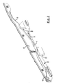
- Figure 2 shows the parts represented in figure 1 in an assembled position, in which a connection between the locking lever 12 and bracket 10 (and thus panel 3) is defined by the hinge pin 13 (and hinge point 14, not visible here), and wherein the T-shaped recess 8 receives the T-shaped member 9. Further, in this position the pin 18 (not visible here) is received in the slide curve 11 and the locking member 21 (neither visible here) is received in the stationary locking guide 22.
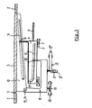
- Figure 3 shows schematically the relative positions and cooperation between the respective parts of the open roof construction in accordance with the present invention. It is noted, that figure 3 only shows a possible embodiment, and that other embodiments are possible.
- Figure 3 shows a situation, in which the panel 3 closes the roof opening 1 and in which the locking member 21 of the locking lever 12 is positioned in a first part 22' of the stationary locking guide 22.
- This first stationary locking guide part 22' extends substantially vertically and connects to a second stationary locking guide part 22" extending substantially horizontally (or, more correctly, in parallel to the direction of movement of the slide 4).
- the slide curve 11 may be provided with such an inclination that the locking lever 12, during such a movement of the slide 4, will slightly rotate around the guide means 19 such that the hinge pin 13/hinge point 14 and thus the panel 3 obtains a corresponding movement, which may be necessary to obtain or maintain an appropriate position at the leading edge of the panel 3 where it engages the stationary roof part 2.
- a longitudinal displacement of the panel 3 can be generated by moving the vertically extending first stationary locking guide part 22' out of the vertical and/or moving the locking guide part 22" out of the horizontal orientation.
- firstly panel engagement means 8 moves along the panel curve 9 and thus the panel 3 will rotate around hinge point 14 to a downwardly tilted position.
- slide engagement means 18 of the locking lever 12 is moved to the left relative to and in the slide curve 11 of the slide 4, and eventually will reach an upwardly extending part 11' thereof.
- the slide engagement means 18 and lever 12 will move upwardly and the locking member 21 will move upwardly out of the vertically extending stationary locking guide part 22'.
- the locking member 21 then will enter the horizontally extending stationary locking guide part 22", such that the locking lever 12 now may move along with the slide 4 to the right.
- the panel 3 also will move to the right.
- the guide means 19, as seen in lengthwise direction of the locking lever 12, is positioned between the hinge pin 13 (hinge point 14) and the slide engagement means 18.
- the hinge pin 13 (hinge point 14) is positioned between the guide means 19 and the slide engagement means 18, or that the hinge pin 13 (hinge point 14), as seen in lengthwise direction of the locking lever 12, coincides with the guide means 19 of the locking lever.
- Such different embodiments will lead to different movements of the hinge point 14 (and, thus, the leading edge of the panel 3) in an upward or downward direction when the locking lever 12 is rotated around the guide means 19 as a result of the slide engagement means 18 thereof moving in an inclined (part of the) slide curve 11 of the slide 4.
- the position of the locking member 21 also may be changed; in stead of being a separate member as illustrated here, such a locking member 21 for example also could coincide with the hinge pin 13 or with the slide engagement means 18.
- stationary slide guide 5 and stationary lever guide 20 are illustrated as distinct members, such guides also could be combined into one single guide.
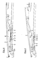
- figure 4 shows a closed position (basically in correspondence with figure 3 );
- figure 5 shows a position in which the panel 3 is rotated upwardly to a tilt position;
- figure 6 shows a position in which the panel 3 is rotated downwardly to a tilt position and
- figure 7 shows a position in which the panel 3, starting from the position illustrated in figure 6 , is moved to the right.
- slide 4 In figure 4 the slide 4 is in a central position and locking member 21 is received in the vertically extending stationary locking guide part 22'.
- slide 4 In figure 5 slide 4 has been moved to the left thus lifting panel 3 to a tilt position due to the cooperation between the panel engagement means 8 and panel curve 9.
- the locking member 21 remains in the stationary locking guide part 22', thus maintaining the locking lever 12 and panel 3 in the same longitudinal position.
- the slide engagement means 18 has moved to the right relative to and in the slide curve 11.
- the slide 4 now has been moved to the right, starting from the position illustrated in figure 4 .
- the panel 3 is rotated to a downwardly tilt position (again as a result of the cooperation between the panel engagement means 8 of the slide 4 and the panel curve 9).
- the slide engagement means (pin) 18 of the locking lever 12 has moved to the left relative to an in the slide curve 11 and has nearly reached the upwardly extending part 11' thereof.
- the locking lever 12, due to the inclined extension of the slide curve 12, has been moved upwardly slightly with its end carrying the slide engagement means 18, such that the locking member 21 of the locking lever 12 is moved upwardly to a position at the transition between the vertically extending stationary locking guide part 22' and horizontally extending stationary locking guide part 22".
Landscapes
- Engineering & Computer Science (AREA)
- Mechanical Engineering (AREA)
- Body Structure For Vehicles (AREA)
- Lock And Its Accessories (AREA)
- Operating, Guiding And Securing Of Roll- Type Closing Members (AREA)
- Fittings On The Vehicle Exterior For Carrying Loads, And Devices For Holding Or Mounting Articles (AREA)
- Conveying And Assembling Of Building Elements In Situ (AREA)
Claims (15)
- Offendachkonstruktion für ein Fahrzeug, mit einer Dachöffnung (1), die in einem stationären Dachabschnitt (2) definiert ist, und einem bewegbaren Paneel (3) zum Öffnen und Schließen der Dachöffnung, mit einem Gleitstück (4), welches entlang einer stationären Gleitführung (5) bewegbar ist und weiches mit Paneeleingriffsmitteln (8) ausgestattet ist, welche mit einer Paneelkurvenbahn (9) des bewegbaren Paneels zusammenwirken, wobei ein Bewegung des Gleitstücks in der Lage ist, eine Kipp- und/oder Verschiebebewegung des Paneels (3) zu erzeugen, gekennzeichnet durch einen Verriegelungshebel (12), welcher mittels eines Gelenkpunkts (14) mit dem Paneel verbunden ist und welcher ausgestattet ist mit erstens Gleiteingriffsmitteln (18), die mit einer Gleitkurvenbahn (11) des Gleitstücks zusammenwirken, zweitens mit Führungsmitteln (19), die mit einer stationären Hebelführung (20) zusammenwirken, und drittens mit einem Verriegelungselement (21), das mit einer stationären Verriegelungsführung (22) zusammenwirkt, sodass in einer ersten Position des Gleitstücks (4) das Verriegelungselement (21) in einem ersten stationären Verriegelungsführungsabschnitt (22) untergebracht ist, wodurch eine translatorische des Verriegelungshebels (12) und des damit verbundenen Paneels (3) verhindert wird, und in einer zweiten Position des Gleitstücks der Verriegelungshebel (21) in einem zweiten stationären Verriegelungsführungsabschnitt (22") untergebracht ist, wodurch eine translatorische Bewegung des Verriegelungshebels (12) und somit des Paneels (3), das mit diesem am Gelenkpunkt (14) verbunden ist, erlaubt wird.
- Offendachkonstruktion gemäß Anspruch 1, wobei die Glertkurvenbahn (11) eine geneigte Erstreckung hat, sodass, wenn das Gleitstück (4) relativ zu dem Verriegelungshebel (12) bewegt wird, die Zusammenwirkung zwischen der Gleitkurvenbahn (11) und den Gleiteingriffsmitteln (18) den Verriegelungshebel (21) in den bzw. aus dem ersten stationären Verriegelungsführungsabschnitt (22') bewegt.
- Offendachkonstruktion gemäß Anspruch 1 oder 2, wobei der erste stationäre Verriegelungsführungsabschnitt (22') sich im Wesentlichen vertikal erstreckt, wobei sich der zweite stationäre Verriegelungsführungsabschnitt (22'') im Wesentlichen horizontal erstreckt.
- Offendachkonstruktion gemäß Anspruch 1 oder 2, wobei der erste stationäre Verriegelungsführungsabschnitt (22') sich relativ zu der Vertikalen geneigt erstreckt und/oder wobei der zweite stationäre Verriegelungsführungsabschnitt (22") sich relativ zu der horizontalen geneigt erstreckt und/oder wobei die Hebelführung (20) sich relativ zu der Horizontalen geneigt erstreckt.
- Offendachkonstruktion gemäß irgendeinem der vorausgehenden Ansprüche, wobei, wenn in Längsrichtung des Verriegelungshebels (12) gesehen, die Führungsmittel (19) zwischen dem Gelenkpunkt (14) und den Gleiteingriffmitteln (18) des Verriegelungshebels (12) positioniert sind.
- Offendachkonstruktion gemäß irgendeinem der Ansprüche 1 bis 4, wobei, wenn in Längsrichtung des Verriegelungshebels (12) gesehen, der Gelenkpunkt (14) zwischen den Führungsmitteln (19) und den Gleiteingriffmitteln (18) der Verriegelungshebels (12) positioniert ist.
- Offendachkonstruktion gemäß irgendeinem der Ansprüche 1 bis 4, wobei, wenn in Längsrichtung des Verriegelungshebels (12) gesehen, der Gelenkpunkt. (14) mit den Führungsmitteln (19) des Verriegelungshebels (12) zusammenfällt.
- Offendachkonstruktion gemäß irgendeinem der vorhergehenden Ansprüche, wobei das Verriegelungselement (21) mit den Gleiteingriffsmitteln (18) zusammenfällt.
- Offendachkonstruktion gemäß irgendeinem der Ansprüche 1 bis 7, wobei das Verriegelungselement (21) mit dem Gelenkpunkt (14) zusammenfällt.
- Offendachkonstruktion gemäß irgendeinem der vorhergehenden Ansprüche, wobei die stationäre Gleitführung (5) und die stationäre Hebelführung (20) zusammenfallen.
- Offendachkonstruktion gemäß irgendeinem der vorhergehenden Ansprüche, wobei der Verriegelungshebel (12) als plattenförmiges Teil ausgebildet ist.
- Offendachkonstruktion gemäß irgendeinem der Ansprüche 1 bis 10, wobei der Verriegelungshebel (12) als ein Element ausgebildet ist, welches einen U-förmigen Querschnitt hat mit zwei im Abstand voneinander angeordneten Wangen (15, 16), die dazwischen eine Lücke (17) definieren, um wenigstens teilweise einen Abschnitt des Paneels (3) aufzunehmen, welcher mit der Paneelkurvenbahn (9) ausgestattet ist.
- Offendachkonstruktion gemäß irgendeinem der vorhergehenden Ansprüche, wobei die Paneelkurvenbahn (9) von einem langgestreckte T-förmigen Element gebildet ist und wobei die Paneeleingriffsmittel (8) des Gleitstücks (4) korrespondierend eine T-förmige Aussparung zum Aufnehmen des T-förmige Elements definieren.
- Offendachkonstruktion gemäß irgendeinem der vorhergehenden Ansprüche, wobei die Gestalt der Gleitkurvenbahn (11) und der Paneelkurvenbahn (9) derart ist, dass während einer Bewegung des Gleitstücks (4) in eine erste Richtung das Verriegelungselement (21) in dem ersten stationären Verriegelungsführungsabschnitt (22') verbleibt und das Paneel (3) nach oben in eine Offenposition gekippt wird, wobei während einer Bewegung des Gleitstücks (4) in die entgegengesetzte Richtung das Verriegelungselement (21) aus dem ersten stationären Verriegelungsführungsabschnitt (22') herausbewegt wird und in den zweiten stationären Verriegelungsführungsabschnitt (22") hineinbewegt wird und das Paneel erstens nach unten gekippt wird in eine Offenposition und zweitens zusammen mit dem Gleitstück (4) in die entgegengesetzte Richtung verschoben wird.
- Offendachkonstruktion gemäß Anspruch 14, wobei die erste Richtung die Vorwärtsrichtung des Fahrzeugs ist und wobei die entgegengesetzte Richtung die Rückwärtsrichtung des Fahrzeugs ist.
Priority Applications (7)
| Application Number | Priority Date | Filing Date | Title |
|---|---|---|---|
| DE602007013548T DE602007013548D1 (de) | 2007-07-16 | 2007-07-16 | Offene Dachkonstruktion für ein Fahrzeug |
| EP07112527A EP2017108B1 (de) | 2007-07-16 | 2007-07-16 | Offene Dachkonstruktion für ein Fahrzeug |
| JP2008182859A JP5311906B2 (ja) | 2007-07-16 | 2008-07-14 | 車両用オープンルーフ構造 |
| US12/172,500 US7753438B2 (en) | 2007-07-16 | 2008-07-14 | Open roof construction for a vehicle |
| CN2008101611454A CN101367327B (zh) | 2007-07-16 | 2008-07-15 | 车辆的敞开的车顶结构 |
| CA002637866A CA2637866A1 (en) | 2007-07-16 | 2008-07-15 | Open roof construction for a vehicle |
| MX2008009216A MX2008009216A (es) | 2007-07-16 | 2008-07-16 | Construccion de techo abierto para un vehiculo. |
Applications Claiming Priority (1)
| Application Number | Priority Date | Filing Date | Title |
|---|---|---|---|
| EP07112527A EP2017108B1 (de) | 2007-07-16 | 2007-07-16 | Offene Dachkonstruktion für ein Fahrzeug |
Publications (2)
| Publication Number | Publication Date |
|---|---|
| EP2017108A1 EP2017108A1 (de) | 2009-01-21 |
| EP2017108B1 true EP2017108B1 (de) | 2011-03-30 |
Family
ID=38659647
Family Applications (1)
| Application Number | Title | Priority Date | Filing Date |
|---|---|---|---|
| EP07112527A Active EP2017108B1 (de) | 2007-07-16 | 2007-07-16 | Offene Dachkonstruktion für ein Fahrzeug |
Country Status (7)
| Country | Link |
|---|---|
| US (1) | US7753438B2 (de) |
| EP (1) | EP2017108B1 (de) |
| JP (1) | JP5311906B2 (de) |
| CN (1) | CN101367327B (de) |
| CA (1) | CA2637866A1 (de) |
| DE (1) | DE602007013548D1 (de) |
| MX (1) | MX2008009216A (de) |
Families Citing this family (24)
| Publication number | Priority date | Publication date | Assignee | Title |
|---|---|---|---|---|
| CN101977787B (zh) * | 2009-02-09 | 2014-03-05 | 韦巴斯托股份公司 | 用于交通工具的可调节本体构件的机构 |
| DE102009011472B4 (de) | 2009-03-03 | 2011-06-09 | Webasto Ag | Fahrzeugdach mit Antriebsschlitten für Deckelelement |
| EP2305500B1 (de) * | 2009-10-05 | 2013-09-25 | Inalfa Roof Systems Group B.V. | Offene Dachkonstruktion für ein Fahrzeug |
| US8297692B2 (en) * | 2009-11-20 | 2012-10-30 | AISIN Technical Center of America, Inc. | Tiltable sun roof for vehicles |
| JP5638367B2 (ja) * | 2010-12-06 | 2014-12-10 | ベバスト ジャパン株式会社 | サンルーフ装置 |
| KR101245802B1 (ko) * | 2010-12-17 | 2013-03-21 | 주식회사 엠에스 오토텍 | 선루프패널 개폐장치 |
| DE102011119991B3 (de) * | 2011-12-02 | 2012-05-24 | Webasto Ag | Seitenblende eines zu öffnenden Fahrzeugdaches |
| EP2644422B1 (de) * | 2012-03-26 | 2014-10-15 | Inalfa Roof Systems Group B.V. | Offene Dachkonstruktion für ein Fahrzeug |
| CN102848889A (zh) * | 2012-10-10 | 2013-01-02 | 上海毓恬冠佳汽车零部件有限公司 | 一种天窗滑动系统 |
| JP6079283B2 (ja) * | 2013-02-08 | 2017-02-15 | アイシン精機株式会社 | 車両用サンルーフ装置 |
| JP6268829B2 (ja) * | 2013-09-06 | 2018-01-31 | アイシン精機株式会社 | 車両用サンルーフ装置 |
| JP6264793B2 (ja) * | 2013-09-06 | 2018-01-24 | アイシン精機株式会社 | 車両用サンルーフ装置 |
| JP6286956B2 (ja) * | 2013-09-06 | 2018-03-07 | アイシン精機株式会社 | 車両用サンルーフ装置 |
| DE102014110234A1 (de) * | 2014-05-14 | 2015-11-19 | Webasto SE | Anordnung mit einem Deckel für ein Fahrzeugdach |
| JP6330558B2 (ja) * | 2014-07-31 | 2018-05-30 | アイシン精機株式会社 | サンルーフ装置 |
| EP3034343B1 (de) * | 2014-12-17 | 2020-05-13 | Inalfa Roof Systems Group B.V. | Dachanordnung für ein Fahrzeug |
| CN104589974B (zh) * | 2014-12-19 | 2017-01-18 | 成都飞机设计研究所 | 一种时序逻辑控制机构 |
| DE102015203056A1 (de) * | 2015-02-20 | 2016-08-25 | Magna Car Top Systems Gmbh | Öffnungs-/Schließmechanik für ein Stoffdach oder Klappdach eines Fahrzeugs |
| CN105480063B (zh) * | 2015-03-31 | 2017-09-26 | 苏州美驰汽车系统有限公司 | 全景天窗机械组 |
| DE102015105380A1 (de) * | 2015-04-09 | 2016-10-13 | Webasto SE | Anordnung mit einem Deckel für ein Fahrzeugdach und Fahrzeugdach für ein Kraftfahrzeug |
| EP3476632B1 (de) * | 2017-10-31 | 2020-05-27 | Inalfa Roof Systems Group B.V. | Offene dachkonstruktion für ein fahrzeug |
| DE202018102477U1 (de) * | 2018-05-03 | 2019-08-12 | Inalfa Roof Systems Group B.V. | Verriegelungsmechanismus und damit bereitgestellte offene Dachkonstruktion |
| US11390150B2 (en) * | 2019-09-19 | 2022-07-19 | Inalfa Roof Systems Group B.V. | Support mechanism for an open-roof assembly in a vehicle roof |
| CN113306373B (zh) * | 2020-02-27 | 2025-10-21 | 英纳法天窗系统集团有限公司 | 用于车辆的车顶打开构造 |
Family Cites Families (7)
| Publication number | Priority date | Publication date | Assignee | Title |
|---|---|---|---|---|
| JPS6353114A (ja) * | 1986-08-22 | 1988-03-07 | Aisin Seiki Co Ltd | T・バ−ル−フ |
| JPH08175185A (ja) * | 1994-12-28 | 1996-07-09 | Aisin Seiki Co Ltd | 可動パネル |
| DE10158174B4 (de) * | 2001-11-28 | 2004-06-17 | Webasto Vehicle Systems International Gmbh | Schiebehebedach für Fahrzeuge |
| JP2003211967A (ja) * | 2002-01-21 | 2003-07-30 | Honda Motor Co Ltd | サンルーフ装置のガラスパネル |
| BR0317858A (pt) * | 2003-05-20 | 2005-12-06 | Antolin Grupo Ing Sa | Estrutura de suporte para tetos solares de automóveis |
| DE10333781B4 (de) * | 2003-07-24 | 2007-04-19 | Webasto Ag | Öffnungsfähiges Fahrzeugdach |
| DE102004061376A1 (de) * | 2004-12-21 | 2006-06-22 | Bayerische Motoren Werke Ag | Verstelleinrichtung für einen Deckel an einem Fahrzeugdach |
-
2007
- 2007-07-16 EP EP07112527A patent/EP2017108B1/de active Active
- 2007-07-16 DE DE602007013548T patent/DE602007013548D1/de active Active
-
2008
- 2008-07-14 JP JP2008182859A patent/JP5311906B2/ja not_active Expired - Fee Related
- 2008-07-14 US US12/172,500 patent/US7753438B2/en active Active
- 2008-07-15 CA CA002637866A patent/CA2637866A1/en not_active Abandoned
- 2008-07-15 CN CN2008101611454A patent/CN101367327B/zh active Active
- 2008-07-16 MX MX2008009216A patent/MX2008009216A/es active IP Right Grant
Also Published As
| Publication number | Publication date |
|---|---|
| DE602007013548D1 (de) | 2011-05-12 |
| JP2009018799A (ja) | 2009-01-29 |
| CN101367327A (zh) | 2009-02-18 |
| EP2017108A1 (de) | 2009-01-21 |
| CA2637866A1 (en) | 2009-01-16 |
| JP5311906B2 (ja) | 2013-10-09 |
| CN101367327B (zh) | 2012-08-15 |
| US20090021056A1 (en) | 2009-01-22 |
| MX2008009216A (es) | 2009-03-05 |
| US7753438B2 (en) | 2010-07-13 |
Similar Documents
| Publication | Publication Date | Title |
|---|---|---|
| EP2017108A1 (de) | Offene Dachkonstruktion für ein Fahrzeug | |
| EP2559576B1 (de) | Sonnendachvorrichtung | |
| US5765908A (en) | Adjustment apparatus for a sunroof | |
| EP2650157B1 (de) | Sonnendachvorrichtung | |
| EP2254764A1 (de) | Offene dachkonstruktion für ein fahrzeug | |
| EP1424234B1 (de) | Konstruktion eines öffnungsfähigen Fahrzeugdaches | |
| US11331988B2 (en) | Roof system for a vehicle | |
| EP3476632B1 (de) | Offene dachkonstruktion für ein fahrzeug | |
| EP2263896B1 (de) | Offene Dachkonstruktion für ein Fahrzeug | |
| EP1494883B1 (de) | Dachanordnung für ein fahrzeug | |
| EP3647094B1 (de) | Dachsystem für ein fahrzeug | |
| EP1331119B1 (de) | Fahrzeug mit Hebeschiebedach | |
| CN109291773B (zh) | 车辆开式天窗结构 | |
| WO2015188863A1 (en) | A drive mechanism for a sunroof of a vehicle and a sunroof apparatus including the same | |
| US7367614B2 (en) | Multi-panel sunshade device | |
| EP4382330B1 (de) | Dachsystem für ein fahrzeug | |
| EP4289647B1 (de) | Dachsystem für ein fahrzeug | |
| JP2005212614A (ja) | サンルーフ装置 | |
| JP2002166727A (ja) | サンルーフ装置 | |
| US11607937B2 (en) | Roof system for a vehicle | |
| EP1533160B1 (de) | Betätigungsvorrichtung für ein öffnungsfähiges Fahrzeugdach | |
| JPH01257622A (ja) | 自動車のセパレートサンルーフ |
Legal Events
| Date | Code | Title | Description |
|---|---|---|---|
| PUAI | Public reference made under article 153(3) epc to a published international application that has entered the european phase |
Free format text: ORIGINAL CODE: 0009012 |
|
| AK | Designated contracting states |
Kind code of ref document: A1 Designated state(s): AT BE BG CH CY CZ DE DK EE ES FI FR GB GR HU IE IS IT LI LT LU LV MC MT NL PL PT RO SE SI SK TR |
|
| AX | Request for extension of the european patent |
Extension state: AL BA HR MK RS |
|
| 17P | Request for examination filed |
Effective date: 20090709 |
|
| 17Q | First examination report despatched |
Effective date: 20090820 |
|
| AKX | Designation fees paid |
Designated state(s): DE FR GB |
|
| GRAP | Despatch of communication of intention to grant a patent |
Free format text: ORIGINAL CODE: EPIDOSNIGR1 |
|
| GRAS | Grant fee paid |
Free format text: ORIGINAL CODE: EPIDOSNIGR3 |
|
| GRAA | (expected) grant |
Free format text: ORIGINAL CODE: 0009210 |
|
| AK | Designated contracting states |
Kind code of ref document: B1 Designated state(s): DE FR GB |
|
| REG | Reference to a national code |
Ref country code: GB Ref legal event code: FG4D |
|
| REF | Corresponds to: |
Ref document number: 602007013548 Country of ref document: DE Date of ref document: 20110512 Kind code of ref document: P |
|
| REG | Reference to a national code |
Ref country code: DE Ref legal event code: R096 Ref document number: 602007013548 Country of ref document: DE Effective date: 20110512 |
|
| PLBE | No opposition filed within time limit |
Free format text: ORIGINAL CODE: 0009261 |
|
| STAA | Information on the status of an ep patent application or granted ep patent |
Free format text: STATUS: NO OPPOSITION FILED WITHIN TIME LIMIT |
|
| 26N | No opposition filed |
Effective date: 20120102 |
|
| GBPC | Gb: european patent ceased through non-payment of renewal fee |
Effective date: 20110716 |
|
| REG | Reference to a national code |
Ref country code: DE Ref legal event code: R097 Ref document number: 602007013548 Country of ref document: DE Effective date: 20120102 |
|
| PG25 | Lapsed in a contracting state [announced via postgrant information from national office to epo] |
Ref country code: GB Free format text: LAPSE BECAUSE OF NON-PAYMENT OF DUE FEES Effective date: 20110716 |
|
| REG | Reference to a national code |
Ref country code: FR Ref legal event code: PLFP Year of fee payment: 10 |
|
| REG | Reference to a national code |
Ref country code: FR Ref legal event code: PLFP Year of fee payment: 11 |
|
| REG | Reference to a national code |
Ref country code: FR Ref legal event code: PLFP Year of fee payment: 12 |
|
| PGFP | Annual fee paid to national office [announced via postgrant information from national office to epo] |
Ref country code: DE Payment date: 20220727 Year of fee payment: 16 |
|
| REG | Reference to a national code |
Ref country code: DE Ref legal event code: R119 Ref document number: 602007013548 Country of ref document: DE |
|
| PG25 | Lapsed in a contracting state [announced via postgrant information from national office to epo] |
Ref country code: DE Free format text: LAPSE BECAUSE OF NON-PAYMENT OF DUE FEES Effective date: 20240201 |
|
| PGFP | Annual fee paid to national office [announced via postgrant information from national office to epo] |
Ref country code: FR Payment date: 20250725 Year of fee payment: 19 |