EP2017127A1 - Dispositif pour régler l'orientation d'un rétroviseur d'une voiture automobile - Google Patents
Dispositif pour régler l'orientation d'un rétroviseur d'une voiture automobile Download PDFInfo
- Publication number
- EP2017127A1 EP2017127A1 EP07014141A EP07014141A EP2017127A1 EP 2017127 A1 EP2017127 A1 EP 2017127A1 EP 07014141 A EP07014141 A EP 07014141A EP 07014141 A EP07014141 A EP 07014141A EP 2017127 A1 EP2017127 A1 EP 2017127A1
- Authority
- EP
- European Patent Office
- Prior art keywords
- gear
- pivot
- reflective element
- element support
- gear rod
- Prior art date
- Legal status (The legal status is an assumption and is not a legal conclusion. Google has not performed a legal analysis and makes no representation as to the accuracy of the status listed.)
- Granted
Links
Images



Classifications
-
- B—PERFORMING OPERATIONS; TRANSPORTING
- B60—VEHICLES IN GENERAL
- B60R—VEHICLES, VEHICLE FITTINGS, OR VEHICLE PARTS, NOT OTHERWISE PROVIDED FOR
- B60R1/00—Optical viewing arrangements; Real-time viewing arrangements for drivers or passengers using optical image capturing systems, e.g. cameras or video systems specially adapted for use in or on vehicles
- B60R1/02—Rear-view mirror arrangements
- B60R1/06—Rear-view mirror arrangements mounted on vehicle exterior
- B60R1/062—Rear-view mirror arrangements mounted on vehicle exterior with remote control for adjusting position
- B60R1/07—Rear-view mirror arrangements mounted on vehicle exterior with remote control for adjusting position by electrically powered actuators
- B60R1/072—Rear-view mirror arrangements mounted on vehicle exterior with remote control for adjusting position by electrically powered actuators for adjusting the mirror relative to its housing
-
- Y—GENERAL TAGGING OF NEW TECHNOLOGICAL DEVELOPMENTS; GENERAL TAGGING OF CROSS-SECTIONAL TECHNOLOGIES SPANNING OVER SEVERAL SECTIONS OF THE IPC; TECHNICAL SUBJECTS COVERED BY FORMER USPC CROSS-REFERENCE ART COLLECTIONS [XRACs] AND DIGESTS
- Y10—TECHNICAL SUBJECTS COVERED BY FORMER USPC
- Y10T—TECHNICAL SUBJECTS COVERED BY FORMER US CLASSIFICATION
- Y10T74/00—Machine element or mechanism
- Y10T74/19—Gearing
- Y10T74/19005—Nonplanetary gearing differential type [e.g., gearless differentials]
Definitions
- the invention relates to a device to adjust the orientation of a mirror of a motorcar according to the preamble of claim 1.
- devices comprising electric motors whose shafts via motion transmission means are connected with a reflective element support, on which a reflective element, such as a mirror, is arranged.
- the bearing between the body and the reflective element support are constructed from polymers including various plastics.
- plastics at least in comparison with metals, it is difficult to achieve required manufacturing tolerances, resulting in slackness and thus little movement or judder of the reflective element support around zero position. This leads to delayed response characteristics when adjusting the orientation of the mirror, since the electric motors in the very beginning of each adjustment procedure first have to break the slackness of the device, particularly of the transmission means.
- the slackness can also result in judder of the door mirrors at high speeds of a motorcar.
- a device to adjust the orientation of a mirror of a motorcar which comprises a body accommodating a first and a second electric motor and a first and a second worm drive driven by said first and second motor respectively.
- the device further comprises a reflective element support pivot-mounted at the body in relation to two perpendicular pivot axles, at which support two gear rods are arranged, each one engaging with said worm drives, a first gear rod engaging with the first worm drive to pivot the reflective element support around a first pivot axle and a second gear rod engaging with the second worm drive to pivot the reflective element support around a second pivot axle.
- Each gear rod is clipped on the reflective element support by inserting it into a mounting seat and engaging an end hole on a pivot.
- the latter is radially orientated towards the centre of the reflective element support and comprises a spherical projection on one of its ends retaining the gear rod on the pivot.
- This arrangement results in that the gear rod can commute in all directions relative to the reflective element support.
- springs are foreseen within the body. Disadvantageously this arrangement does not reduce slackness and thus judder because of the slackness of the commuting gear rods.
- a further disadvantage of this device is, that when manually adjusting the mirror, or, during overload conditions e.g. due to internal or external forces, the worm drives avoid back driving the gear and thus the electric motors. Due to this in overload conditions the springs have to allow the gear rods to disengage the worm drives and to skip their gearings. This results in noises and also abrasions of the gearing of the gear rods and worm drives.
- a device to adjust the orientation of a mirror of a motorcar which comprises a body accommodating a first and a second electric motor and a first and a second gear train driven by said first and second motor respectively.
- the device further comprises a reflective element support pivot-mounted at the body in relation to two perpendicular pivot axles, at which support two gear rods are arranged, each one engaging with said gear trains, a first gear rod engaging with the first gear train to pivot the reflective element support around a first pivot axle and a second gear rod engaging with the second gear train to pivot the reflective element support around a second pivot axle.
- Each gear rod is mounted at the reflective element support by a ball head, allowing it to commute in any direction.
- a spring is arranged within said duct.
- a disadvantage of all known devices is, that for a given angle of travel they require a relatively large, particularly deep installation space.
- An object of the invention is to develop a device to adjust the orientation of a mirror of a motorcar requiring less installation space for a given angel of travel and having improved response characteristics, reduced abrasions in operation and overload conditions and reduced noises in overload conditions.
- a device to adjust the orientation of a mirror of a motorcar comprising a body accommodating a first and a second electric motor and a first and a second gear driven by said first and second motor respectively.
- Said device further comprises a reflective element support pivot-mounted at the body in relation to two pivot axles, at which reflective element support two gear rods are arranged engaging with said gears, a first gear rod engaging with the first gear to pivot the reflective element support around a first pivot axle and a second gear rod engaging with the second gear to pivot the reflective element support around a second pivot axle.
- the gear rods are formed as circular arc sections each, particularly reducing the depth of the device and allowing it to fit in a small space.
- the body of the device also accommodates means to springy press the first and second gear rod against the first and second gear respectively, eliminating relative moving between the gearing of the gear rods and the gears in operation conditions, and the gears comprise safety clutch means each, allowing the gears to slip in overload conditions.
- the centre of the circular arc of the first gear rod has not to be the second pivot axle.
- each gear rod can be mounted in the support such that it can articulate.
- the gear teeth on each gear rod preferably are tapered to allow this movement in one direction. Movement in the other direction occurs as the gear rod rolls around the gear.
- the means to springy press the first and second gear rod against the first and second gear respectively preferably are positioned so that this movement is allowed.
- the means to springy press the gear rods against the gears improve the response characteristics of the device, since relative moving between the gearing of the gear rods and gears is eliminated.
- this damping is abrasion free and without degeneration over lifetime.
- Due to the safety clutch means abrasions of the gearing of the gear rods and gears and thus noises caused by overload conditions, like e.g.
- gears that are non-back drivable such as gears having at least one worm drive
- gears constructed from polymers including various plastics are employed.
- the curved gear rods reduce installation space requirements of the device at a given angel of travel of the reflective element support. Particularly the curved gear rods reduce the depth of the device and allow it to fit in a small space.
- the safety clutch means preferably comprise a disc spring having a friction face forced against a corresponding friction face on another gear train member.
- Disc springs or bellview washers are compact and low cost.
- the safety clutch means preferably comprise a drive shaft, a torque transmission member co-axially mounted to the drive shaft, a clutch member operably connected to or integral with the torque transmission member and having a first friction face.
- the safety clutch means further comprise a disc spring mounted around the drive shaft and having a second friction face engaging the first friction face, a resilient retainer retaining the disc spring in a compressed condition in which the first and second friction faces are compressed together to allow torque transmission.
- the retainer includes a fractured ring having first and second ends resulting from the fracture, the ends adjacent and biased towards each other.
- the safety clutch means further preferably comprise a third friction face on the gear opposite of the first friction face and a cone on the shaft.
- Said cone has a fourth friction face against which the retainer via the disc spring presses the third friction face to improve torque transmission between the shaft and the gear.
- the advantage of this is that it lowers the spring force required to achieve a certain torque. This means that the pressure is lowered and therefore the clutch will wear less.
- the gear rods are formed as circular arc sections each, wherein the centre of the circular arc section of the first gear rod is the first pivot axle and the centre of the circular arc section of the second gear rod is the second pivot axle, and wherein each gear rod is fixed arranged at the reflective element support at least in relation to the pivot axle around which it pivots the reflective element support and in relation to an axle perpendicular to the two pivot axles.
- each, i.e. the first and the second gear rod preferably is pivot mounted in relation to the pivot axle around which the other, i.e. the second and the first gear rod pivots the reflective element support.
- the means to springy press the first and second gear rod against the first and second gear respectively comprise one spring per gear rod and gear.
- the spring is a leaf spring.
- the means to springy press the first and second gear rod against the first and second gear respectively comprise a spring jack pressing the first gear rod against the first gear as well as pressing the second gear rod against the second gear.
- the spring jack preferably comprises a spring jack support arranged within the body between the gear rods and the electric motors and/or the gears, a first extension with a first free end springy pressing the first gear rod against the first gear and a first fixed end connected with the spring jack support, plus a second extension with a second free end springy pressing the second gear rod against the second gear and a second fixed end connected with the spring jack support.
- the pivot axles are arranged perpendicular to each other.
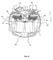
- a device 100 to adjust the orientation of a mirror of a motorcar shown in Figs. 13 , 15 , 16 and 17 comprises a body 110 having an upper half 6 and a lower half 18 accommodating a first and a second electric motor 7, 8 and a first and a second gear train 120, 121 driven by said first and second motor 7, 8 respectively.
- Each gear train 120, 121 comprises a worm drive 15 driven by one of the electric motors 7, 8.
- the worm drive 15 engages a gear 40 mounted on a drive shaft 20.
- An output gear 35 is integral part of the drive shaft 20.
- Said device 100 further comprises a reflective element support 4 pivot-mounted in a spherical pivot bearing 5 at the body 110 in relation to two pivot axles, arranged perpendicular to each other.
- each gear rod 17, 19 engages the output gear 35 of one of the two gears 120, 121.
- the body 110 of the device 100 also accommodates means 9 to springy press the first and second gear rod 17, 19 against the first and second gear train 120, 121 respectively, eliminating relative movement between the gearing of the gear rods 17, 19 and the gear trains 120, 121 in operation conditions.
- the gear trains 120, 121 comprise safety clutch means 10 each, allowing the gear trains 120, 121 to slip in overload conditions.
- the safety clutch means 10 allow the gear 40 to slip versus the drive shaft 20.
- the safety clutch means 10 are described in detail thereinafter.
- the body 110 further accommodates a carrier circuit 16 to electrically connect the electric motors 7, 8.
- the upper 6 and lower half 18 of the body 110 are held together by a single screw 1 which also fixes the reflective element support 4 in the spherical pivot bearing 5 at the body 110.
- a pivot spring 3 and a pivot ball 2 are foreseen via which the screw 1 holds the reflective element support 4 in the spherical pivot bearing 5 on the body.
- the gear rods 17, 19 are formed as circular arc sections each, wherein the centre of the circular arc section of the first gear rod 17 is the first pivot axle, and the centre of the circular arc section of the second gear rod 19 is the second pivot axle.
- Each gear rod 17, 19 is fixed arranged at the reflective element support 4 at least in relation to the pivot axle around which it pivots the reflective element support 4 and in relation to an axle perpendicular to the two pivot axles.
- each, i.e. the first and the second gear rod 17, 19, preferably is pivot mounted in relation to the pivot axle around which the other, i.e. the second and the first gear rod 19, 17, pivots the reflective element support 4.
- the means 9 to springy press the first and second gear rod 17, 19 against the first and second gear train 120, 121 respectively comprise a spring jack 9 pressing the first gear rod 17 against the output gear 35 of the first gear train 120 and pressing the second gear rod 19 against the output gear 35 of the second gear train 121.
- the spring jack 9 shown in detail in Fig. 14 comprises a spring jack support 90 arranged within the body 110 between the gear rods 17, 19 and the electric motors 7, 8 and/or the gears 120, 121, a first extension 91 with a first free end 92 forming a shoulder springy pressing the first gear rod 17 against the output gear 35 of the first gear train 120 and a first fixed end 93 connected with the spring jack support 91, plus a second extension 94 with a second free end 95 also forming a shoulder springy pressing the second gear rod 19 against the output gear 35 of the second gear train 121 and a second fixed end 96 connected with the spring jack support 90.
- a safety clutch means 10 in form of a clutch assembly 10 is shown in detail.
- the assembly 10 includes a drive shaft 20, the shaft 20 having a plurality of shoulders 30.
- a torque transmission member the form of a helical gear 40 is coaxially mounted to the drive shaft 20.
- a clutch member 41 is integral with the gear 40 and has a first friction face 44. It is also thinkable that the clutch member 41 maybe separate from the torque transmission member 40.
- a disc spring 50 most clearly shown in Fig. 2 , is mounted around the drive shaft 20 and has a second friction face 54 engaging the first friction face 44.
- a resilient retainer 60 retains the disc spring 50 in a compressed condition in which the first and second friction face 44 and 54 are compressed together to allow torque transmission between the shaft 20 and the gear 40 via a third friction face 46 on the gear 40 opposite of the first friction face 44 and a fourth friction face 22 on a cone 24 on the shaft 20 ( Fig. 6 ).
- the retainer is characterized in that it includes a fractured ring having first and second ends 62 and 64, the ends resulting from a fracture and the ends being biased towards each other. The ends 62 and 64 are biased toward each other by the resilience of the material from which the retainer 60 is constructed.
- the retainer 60 can be constructed from various materials. In the embodiment of the invention shown, the retainer is constructed from plastic including a stiffening additive.
- Stiffening additives such as carbon and glass fiber may be used.
- Various plastics including nylon and Polytetrafluoroethylene (PTFE) may be used.
- a double reduction worm gear train comprising the worm drive 15 and a worm drive 11 on the shaft of the electric motor 7 or 8 ( Fig. 13 and Fig. 15 ) is employed between the motor 7 or 8 and gear 40 to achieve the desired gearing.
- the shaft 20 rotates with the gear 40 by virtue of the friction between the first friction face 44 of the clutch area 41 of the gear 40 engaging with the second friction face 54 on the disc spring 50.
- the disc spring 50 is keyed to the shaft 20 by virtue of tabs 57 that key into corresponding slots 27 on shaft 20 as can most clearly can be seen in Figs. 2 and 3 .
- Output gear 35 is keyed to the disc spring 50 through slots 27.
- the output gear 35 mates with a gear rod 17, 19 that drives a reflective element support 4 ( Fig. 13 ).
- a reflective element mounted on that support 4 typically is a mirror.
- the disc spring 50 is correctly compressed between the friction face 44 of the clutch member 41 and the retainer 60 so that an appropriate level torque can be transmitted without slippage. There must be sufficient torque to allow the gear trains 120, 121 to drive the reflective element support 4 against secretions such as dirt and ice. On the other hand, the torque transmission should not be too high otherwise damage may occur to the gear trains 120, 121 when an operator manually attempts to override the mechanism by pressing on the surface of e.g. the mirror glass.
- the retainer 60 of the invention is important in achieving the goal of appropriate torque transmission that is torque transmission within a specified tolerance.
- the retainer 60 includes a necked region 63 that will preferentially fracture when sufficient hoop stress is applied.
- a method of assembling the compact clutch assembly will now be described with reference to Figs. 2 , 11 , 12 and 13 .
- a clutch member 41 mounted around a drive shaft 20 is provided.
- the clutch member has a first friction face 44.
- a disc spring 50 is mounted around the shaft so that a second friction face 54 is engagable with the first friction face 44.
- An annular retainer 60 is then forced in an axial direction against the ramped faces 31 of the shoulders 30 and the spring 50 so as to create sufficient hoop stress to create a fracture through the retainer 50, at necked region 63, the fracture allowing the retainer 50 to expand and pass over the shoulders 30. This is shown progressively in Figs. 11, 12 and 13 .
- the necked area 63 of the retainer 60 is designed such that it acts as a complete hoop during assembly to enable the retainer 60 to centralize itself on the ramped faces 31 of the shoulders 30.
- the retainer 60 is shown in its fractured state passing over the outer faces 33 of the shoulders 30. Because the retainer 60 is now fractured, the compressive force it exerts on the outer faces 33 of the shoulders 30 is relatively small. This ensures that damage to the shoulders 30 is minimized and that the exact position of the retainer 60 when it reaches the position under the undercut face 32 is predictable and controllable. This in turn means that the degree of compression of the spring 50 between the retainer 60 and the gear 40 is predictable and controllable.
- the afore-mentioned centralizing of the retainer 60 and subsequent splitting of the retainer 60 eliminates or at least reduces damage to the ramped faces 31, the outer faces 33 and the under cut faces 32 of the shoulders 30.
- the effect of this is to more predictably and controllably compress the spring 50 between the retainer 60 and the gear 40.
Landscapes
- Engineering & Computer Science (AREA)
- Multimedia (AREA)
- Mechanical Engineering (AREA)
- Rear-View Mirror Devices That Are Mounted On The Exterior Of The Vehicle (AREA)
- Gear Transmission (AREA)
Priority Applications (5)
| Application Number | Priority Date | Filing Date | Title |
|---|---|---|---|
| AT07014141T ATE482850T1 (de) | 2007-07-19 | 2007-07-19 | Vorrichtung zum anpassen der ausrichtung eines spiegels eines kraftfahrzeugs |
| DE602007009516T DE602007009516D1 (de) | 2007-07-19 | 2007-07-19 | Vorrichtung zum Anpassen der Ausrichtung eines Spiegels eines Kraftfahrzeugs |
| EP07014141A EP2017127B1 (fr) | 2007-07-19 | 2007-07-19 | Dispositif pour régler l'orientation d'un rétroviseur d'une voiture automobile |
| CN200810130305.9A CN101348094B (zh) | 2007-07-19 | 2008-07-04 | 用于调整汽车反光镜方向的装置 |
| US12/171,862 US8127641B2 (en) | 2007-07-19 | 2008-07-11 | Device to adjust the orientation of a mirror of a motorcar |
Applications Claiming Priority (1)
| Application Number | Priority Date | Filing Date | Title |
|---|---|---|---|
| EP07014141A EP2017127B1 (fr) | 2007-07-19 | 2007-07-19 | Dispositif pour régler l'orientation d'un rétroviseur d'une voiture automobile |
Publications (2)
| Publication Number | Publication Date |
|---|---|
| EP2017127A1 true EP2017127A1 (fr) | 2009-01-21 |
| EP2017127B1 EP2017127B1 (fr) | 2010-09-29 |
Family
ID=38800797
Family Applications (1)
| Application Number | Title | Priority Date | Filing Date |
|---|---|---|---|
| EP07014141A Active EP2017127B1 (fr) | 2007-07-19 | 2007-07-19 | Dispositif pour régler l'orientation d'un rétroviseur d'une voiture automobile |
Country Status (5)
| Country | Link |
|---|---|
| US (1) | US8127641B2 (fr) |
| EP (1) | EP2017127B1 (fr) |
| CN (1) | CN101348094B (fr) |
| AT (1) | ATE482850T1 (fr) |
| DE (1) | DE602007009516D1 (fr) |
Cited By (17)
| Publication number | Priority date | Publication date | Assignee | Title |
|---|---|---|---|---|
| EP2017488A1 (fr) * | 2007-07-20 | 2009-01-21 | Visiocorp Patents S.à.r.l. | Procédé d'assemblage d'embrayage compact et appareil |
| EP2492145A1 (fr) | 2011-02-23 | 2012-08-29 | SMR Patents S.à.r.l. | Rétroviseur extérieur réglable |
| EP2716927A1 (fr) | 2012-10-02 | 2014-04-09 | Fico Mirrors, S.A. | Embrayage approprié pour rétroviseurs électriques de véhicule |
| WO2014178708A1 (fr) * | 2013-05-03 | 2014-11-06 | Mci (Mirror Controls International) Netherlands B.V. | Mécanisme moteur et rétroviseur extérieur pour un véhicule équipé d'un tel mécanisme moteur |
| WO2016048140A1 (fr) * | 2014-09-22 | 2016-03-31 | Mci (Mirror Controls International) Netherlands B.V. | Mécanisme de commande de mouvement, dispositif de rétroviseur externe et véhicule |
| EP3409537A1 (fr) | 2017-05-30 | 2018-12-05 | SMR Patents S.à.r.l. | Section de tête pour un dispositif de vision arrière |
| US10261648B2 (en) | 2009-10-07 | 2019-04-16 | Magna Mirrors Of America, Inc. | Exterior rearview mirror assembly |
| EP3480062A1 (fr) | 2017-11-01 | 2019-05-08 | SMR Patents S.à.r.l. | Dispositif de rétroviseur comportant un ensemble à tête mobile |
| EP3543070A2 (fr) | 2018-03-15 | 2019-09-25 | SMR Patents S.à.r.l. | Dispositif de rétroviseur comprenant un ensemble de tête mobile et son procédé d'assemblage |
| CN111503240A (zh) * | 2019-01-30 | 2020-08-07 | 广东德昌电机有限公司 | 多组件齿轮及其制造方法 |
| US10913395B2 (en) | 2010-02-10 | 2021-02-09 | Magna Mirrors Of America, Inc. | Exterior rearview mirror assembly |
| US11148596B2 (en) | 2017-08-23 | 2021-10-19 | Magna Mirrors Of America, Inc. | Exterior rearview mirror assembly |
| US11325535B2 (en) | 2010-02-10 | 2022-05-10 | Magna Mirrors Of America, Inc. | Exterior rearview mirror assembly |
| US11351919B2 (en) | 2018-05-24 | 2022-06-07 | Magna Mirrors Of America, Inc. | Exterior rearview mirror assembly |
| US11498486B2 (en) | 2009-10-07 | 2022-11-15 | Magna Mirrors Of America, Inc. | Vehicular exterior rearview mirror assembly |
| US12115913B2 (en) | 2010-02-10 | 2024-10-15 | Magna Mirrors Of America, Inc. | Vehicular exterior rearview mirror system |
| US12668184B2 (en) | 2010-02-10 | 2026-06-30 | Magna Mirrors Of America, Inc. | Vehicular exterior rearview mirror assembly |
Families Citing this family (9)
| Publication number | Priority date | Publication date | Assignee | Title |
|---|---|---|---|---|
| US9242606B2 (en) * | 2012-11-09 | 2016-01-26 | Magna Mirrors Of America, Inc. | Exterior mirror assembly with actuator |
| DE102013201434B3 (de) * | 2013-01-29 | 2014-05-28 | Mekra Lang Gmbh & Co. Kg | Elektrisch rotatorische Verstelleinheit sowie indirektes Sichtsystem für Fahrzeuge mit einer solchen Verstelleinheit |
| NL2010811C2 (nl) * | 2013-05-16 | 2014-11-24 | Mci Mirror Controls Int Nl Bv | Spiegel-verstelunit en buitenspiegel voor een motorvoertuig omvattende een dergelijke spiegel-verstelunit. |
| KR101652889B1 (ko) * | 2015-03-13 | 2016-09-01 | 주식회사 호영자동차부품 | 자동차용 아웃사이드미러 조정 장치 |
| DE102016108373A1 (de) | 2016-05-04 | 2017-11-09 | SMR Patents S.à.r.l. | Positioniersystem für eine Rückblickanzeigevorrichtung |
| CN106427790B (zh) * | 2016-08-28 | 2021-09-14 | 宁波精成车业有限公司 | 小客电动镜面驱动器 |
| US20200410764A1 (en) * | 2019-06-28 | 2020-12-31 | Snap Inc. | Real-time augmented-reality costuming |
| US12481149B2 (en) | 2021-12-16 | 2025-11-25 | Waymo Llc | Tapered mirror shaft |
| DE102024137450A1 (de) * | 2024-12-12 | 2026-06-18 | Motherson Innovations Company Limited | Eine kupplungsbaugruppe, eine rückspiegelvorrichtung, ein fahrzeug und ein verfahren zu deren herstellung |
Citations (6)
| Publication number | Priority date | Publication date | Assignee | Title |
|---|---|---|---|---|
| DE3914334A1 (de) * | 1989-04-29 | 1990-10-31 | Kienzle Uhrenfabriken Gmbh | Verstellvorrichtung fuer einen kfz-aussenspiegel |
| EP0596182A1 (fr) | 1992-11-04 | 1994-05-11 | COMMER S.p.A. | Installation pour régler l'orientation des miroirs de porte de véhicules |
| US5701211A (en) | 1995-03-31 | 1997-12-23 | United Technologies Automotive Systems, Inc. | Vehicle mirror adjustment gear train |
| DE10308067A1 (de) * | 2001-10-25 | 2004-09-09 | Em Kunststofftechnik Gmbh | Antriebsanordnung zum gesteuerten mehrachsigen Verstellen, insbesondere eines Kraftfahrzeug-Rückblickspiegels |
| US20050099710A1 (en) * | 2003-11-10 | 2005-05-12 | Pro Quip International Korea Co., Ltd. | Clutch structure of automative mirror adjustment mechanism |
| WO2006045159A1 (fr) * | 2004-10-29 | 2006-05-04 | Schefenacker Vision Systems Australia Pty Ltd | Moyen pour empecher le desaccouplement entre une cremaillere et un pignon |
Family Cites Families (6)
| Publication number | Priority date | Publication date | Assignee | Title |
|---|---|---|---|---|
| DE69202664T2 (de) * | 1991-10-04 | 1995-10-19 | Britax Rainsfords Pty Ltd | Antriebsmodul für einen Spiegel. |
| DE60123923T2 (de) * | 2000-01-19 | 2007-06-06 | Stoneridge Control Devices, Inc., Canton | Elektromechanische bedienungseinrichtung |
| WO2005073038A1 (fr) * | 2004-01-28 | 2005-08-11 | Schefenacker Vision Systems Australia Pty Ltd | Retroviseur telescopique externe a commande pour vehicule |
| NL1025433C2 (nl) * | 2004-02-06 | 2005-08-09 | Iku Holding Montfoort Bv | Scharnieractuator en werkwijze voor het ten opzichte van elkaar verstellen van twee delen van een scharnieractuator. |
| NL1025524C2 (nl) * | 2004-02-19 | 2005-08-22 | Iku Holding Montfoort Bv | Spiegelverstelmechanisme, buitenspiegeleenheid en werkwijze. |
| DE102004022523A1 (de) * | 2004-05-05 | 2005-12-01 | Donnelly Hohe Gmbh & Co. Kg | Innenspiegel mit Antriebseinrichtung zur Verstellung eines Keilspiegelglases |
-
2007
- 2007-07-19 AT AT07014141T patent/ATE482850T1/de not_active IP Right Cessation
- 2007-07-19 DE DE602007009516T patent/DE602007009516D1/de active Active
- 2007-07-19 EP EP07014141A patent/EP2017127B1/fr active Active
-
2008
- 2008-07-04 CN CN200810130305.9A patent/CN101348094B/zh active Active
- 2008-07-11 US US12/171,862 patent/US8127641B2/en active Active
Patent Citations (6)
| Publication number | Priority date | Publication date | Assignee | Title |
|---|---|---|---|---|
| DE3914334A1 (de) * | 1989-04-29 | 1990-10-31 | Kienzle Uhrenfabriken Gmbh | Verstellvorrichtung fuer einen kfz-aussenspiegel |
| EP0596182A1 (fr) | 1992-11-04 | 1994-05-11 | COMMER S.p.A. | Installation pour régler l'orientation des miroirs de porte de véhicules |
| US5701211A (en) | 1995-03-31 | 1997-12-23 | United Technologies Automotive Systems, Inc. | Vehicle mirror adjustment gear train |
| DE10308067A1 (de) * | 2001-10-25 | 2004-09-09 | Em Kunststofftechnik Gmbh | Antriebsanordnung zum gesteuerten mehrachsigen Verstellen, insbesondere eines Kraftfahrzeug-Rückblickspiegels |
| US20050099710A1 (en) * | 2003-11-10 | 2005-05-12 | Pro Quip International Korea Co., Ltd. | Clutch structure of automative mirror adjustment mechanism |
| WO2006045159A1 (fr) * | 2004-10-29 | 2006-05-04 | Schefenacker Vision Systems Australia Pty Ltd | Moyen pour empecher le desaccouplement entre une cremaillere et un pignon |
Cited By (36)
| Publication number | Priority date | Publication date | Assignee | Title |
|---|---|---|---|---|
| EP2017488A1 (fr) * | 2007-07-20 | 2009-01-21 | Visiocorp Patents S.à.r.l. | Procédé d'assemblage d'embrayage compact et appareil |
| US10261648B2 (en) | 2009-10-07 | 2019-04-16 | Magna Mirrors Of America, Inc. | Exterior rearview mirror assembly |
| US11970111B2 (en) | 2009-10-07 | 2024-04-30 | Magna Mirrors Of America, Inc. | Vehicular exterior rearview mirror assembly |
| US11498486B2 (en) | 2009-10-07 | 2022-11-15 | Magna Mirrors Of America, Inc. | Vehicular exterior rearview mirror assembly |
| US10906467B2 (en) | 2009-10-07 | 2021-02-02 | Magna Mirrors Of America, Inc. | Exterior rearview mirror assembly |
| US11697373B2 (en) | 2009-10-07 | 2023-07-11 | Magna Mirrors Of America, Inc. | Vehicular exterior rearview mirror assembly |
| US12246649B2 (en) | 2009-10-07 | 2025-03-11 | Magna Mirrors Of America, Inc. | Vehicular exterior rearview mirror assembly |
| US12115913B2 (en) | 2010-02-10 | 2024-10-15 | Magna Mirrors Of America, Inc. | Vehicular exterior rearview mirror system |
| US11794648B2 (en) | 2010-02-10 | 2023-10-24 | Magna Mirrors Of America, Inc. | Exterior rearview mirror assembly |
| US12668184B2 (en) | 2010-02-10 | 2026-06-30 | Magna Mirrors Of America, Inc. | Vehicular exterior rearview mirror assembly |
| US11325535B2 (en) | 2010-02-10 | 2022-05-10 | Magna Mirrors Of America, Inc. | Exterior rearview mirror assembly |
| US10913395B2 (en) | 2010-02-10 | 2021-02-09 | Magna Mirrors Of America, Inc. | Exterior rearview mirror assembly |
| EP2492145A1 (fr) | 2011-02-23 | 2012-08-29 | SMR Patents S.à.r.l. | Rétroviseur extérieur réglable |
| EP2716927A1 (fr) | 2012-10-02 | 2014-04-09 | Fico Mirrors, S.A. | Embrayage approprié pour rétroviseurs électriques de véhicule |
| US9200680B2 (en) | 2012-10-02 | 2015-12-01 | Fico Mirrors, S.A. | Clutch suitable for vehicles' powered mirrors |
| JP2014073830A (ja) * | 2012-10-02 | 2014-04-24 | Fico Mirrors Sa | 車の電動ミラーに適したクラッチ |
| US10076999B2 (en) | 2013-05-03 | 2018-09-18 | Mci (Mirror Controls International) Netherlands B.V. | Movement mechanism and wing mirror for a vehicle provided with such a movement mechanism |
| US10227044B2 (en) | 2013-05-03 | 2019-03-12 | Mci (Mirror Controls International) Netherlands B.V. | Movement mechanism and wing mirror for a vehicle provided with such a movement mechanism |
| WO2014178708A1 (fr) * | 2013-05-03 | 2014-11-06 | Mci (Mirror Controls International) Netherlands B.V. | Mécanisme moteur et rétroviseur extérieur pour un véhicule équipé d'un tel mécanisme moteur |
| CN105307902A (zh) * | 2013-05-03 | 2016-02-03 | 荷兰反光镜控制器国际有限公司 | 运动机构及用于设有该运动机构的车辆的后视镜 |
| NL2013509B1 (nl) * | 2014-09-22 | 2016-09-29 | MCI (Mirror Controls International) Netherlands B V | Bewegingsmechanisme, buitenspiegelinrichting en voertuig. |
| WO2016048140A1 (fr) * | 2014-09-22 | 2016-03-31 | Mci (Mirror Controls International) Netherlands B.V. | Mécanisme de commande de mouvement, dispositif de rétroviseur externe et véhicule |
| EP3409537A1 (fr) | 2017-05-30 | 2018-12-05 | SMR Patents S.à.r.l. | Section de tête pour un dispositif de vision arrière |
| US11691567B2 (en) | 2017-08-23 | 2023-07-04 | Magna Mirrors Of America, Inc. | Exterior rearview mirror assembly |
| US12049171B2 (en) | 2017-08-23 | 2024-07-30 | Magna Mirrors Of America, Inc. | Exterior rearview mirror assembly |
| US11148596B2 (en) | 2017-08-23 | 2021-10-19 | Magna Mirrors Of America, Inc. | Exterior rearview mirror assembly |
| EP3480062A1 (fr) | 2017-11-01 | 2019-05-08 | SMR Patents S.à.r.l. | Dispositif de rétroviseur comportant un ensemble à tête mobile |
| EP3543070A2 (fr) | 2018-03-15 | 2019-09-25 | SMR Patents S.à.r.l. | Dispositif de rétroviseur comprenant un ensemble de tête mobile et son procédé d'assemblage |
| EP4303076A2 (fr) | 2018-03-15 | 2024-01-10 | SMR Patents S.à.r.l. | Dispositif de rétroviseur comportant un ensemble à tête mobile |
| EP4467392A2 (fr) | 2018-03-15 | 2024-11-27 | SMR Patents Sarl | Dispositif de rétroviseur comportant un ensemble à tête mobile |
| EP3835131A1 (fr) | 2018-03-15 | 2021-06-16 | SMR Patents S.à.r.l. | Dispositif de rétroviseur comportant un ensemble à tête mobile |
| US11351919B2 (en) | 2018-05-24 | 2022-06-07 | Magna Mirrors Of America, Inc. | Exterior rearview mirror assembly |
| US11623568B2 (en) | 2018-05-24 | 2023-04-11 | Magna Mirrors Of America, Inc. | Exterior rearview mirror assembly |
| US12071074B2 (en) | 2018-05-24 | 2024-08-27 | Magna Mirrors Of America, Inc. | Exterior rearview mirror assembly |
| CN111503240B (zh) * | 2019-01-30 | 2023-09-19 | 广东德昌电机有限公司 | 多组件齿轮及其制造方法 |
| CN111503240A (zh) * | 2019-01-30 | 2020-08-07 | 广东德昌电机有限公司 | 多组件齿轮及其制造方法 |
Also Published As
| Publication number | Publication date |
|---|---|
| EP2017127B1 (fr) | 2010-09-29 |
| CN101348094A (zh) | 2009-01-21 |
| DE602007009516D1 (de) | 2010-11-11 |
| US8127641B2 (en) | 2012-03-06 |
| CN101348094B (zh) | 2011-01-05 |
| US20090021034A1 (en) | 2009-01-22 |
| ATE482850T1 (de) | 2010-10-15 |
Similar Documents
| Publication | Publication Date | Title |
|---|---|---|
| EP2017127B1 (fr) | Dispositif pour régler l'orientation d'un rétroviseur d'une voiture automobile | |
| US4652781A (en) | Drive unit for adjusting window panes, sunroofs, seats and similar motor vehicle parts | |
| KR100998371B1 (ko) | 전기 구동식 캠축 조정기 | |
| US7490695B2 (en) | Electric power steering apparatus | |
| EP1657129B1 (fr) | Dispositif d'embrayage et moteur ayant un tel dispositif | |
| WO2011073089A1 (fr) | Mécanisme de direction avec palier fixe et palier libre pour pignon à vis | |
| DE102005012938A1 (de) | Getriebe-Antriebseinheit mit einer Lastdrehmomentsperre | |
| WO2011125372A1 (fr) | Tige de liaison et mécanisme d'inclinaison double face | |
| KR20160042895A (ko) | 기어 구동 장치, 및 자동차용 편의 구동 장치 | |
| EP2716927A1 (fr) | Embrayage approprié pour rétroviseurs électriques de véhicule | |
| EP1058018B1 (fr) | Embrayage multi-disques avec dispositif hélicoidal pour le réglage de la compression axiale sur les disques | |
| DE102014210588A1 (de) | Anordnung zum Antreiben einer Verstellwelle zum Verstellen des Expansionshubes und/oder des Verdichtungsverhältnisses eines Verbrennungsmotors | |
| US6809440B2 (en) | Space-saving, damping coupling mechanism for worms in geared actuators | |
| DE19927658A1 (de) | Pumpenaggregat | |
| JP4369393B2 (ja) | クラッチ装置、モータ装置、及びワイパモータ | |
| US20090020387A1 (en) | Compact Clutch Assembly Method and Apparatus | |
| CN106169834B (zh) | 变速驱动装置和用于加工变速驱动装置的方法 | |
| CN111734748A (zh) | 大扭矩防震联轴器 | |
| CN114001136A (zh) | 一种高效高强度的自锁调节机构 | |
| EP1245866A2 (fr) | Actionneur électrique pour véhicule à moteur | |
| WO2020253906A1 (fr) | Réducteur harmonique et procédé pour le montage d'un réducteur harmonique | |
| CN223305875U (zh) | 一种起动机及其单向器 | |
| CN220605681U (zh) | 一种便于安装及拆卸的电机轴组件 | |
| EP1544488B1 (fr) | Unité d'entraînement, de préference une unité d'entraînement de lève-vitre, avec un élément d'adaptation | |
| CN212079977U (zh) | 一种限矩离合器 |
Legal Events
| Date | Code | Title | Description |
|---|---|---|---|
| PUAI | Public reference made under article 153(3) epc to a published international application that has entered the european phase |
Free format text: ORIGINAL CODE: 0009012 |
|
| 17P | Request for examination filed |
Effective date: 20080117 |
|
| AK | Designated contracting states |
Kind code of ref document: A1 Designated state(s): AT BE BG CH CY CZ DE DK EE ES FI FR GB GR HU IE IS IT LI LT LU LV MC MT NL PL PT RO SE SI SK TR |
|
| AX | Request for extension of the european patent |
Extension state: AL BA HR MK RS |
|
| AKX | Designation fees paid |
Designated state(s): AT BE BG CH CY CZ DE DK EE ES FI FR GB GR HU IE IS IT LI LT LU LV MC MT NL PL PT RO SE SI SK TR |
|
| RAP1 | Party data changed (applicant data changed or rights of an application transferred) |
Owner name: SMR PATENTS S.A.R.L. |
|
| GRAP | Despatch of communication of intention to grant a patent |
Free format text: ORIGINAL CODE: EPIDOSNIGR1 |
|
| GRAS | Grant fee paid |
Free format text: ORIGINAL CODE: EPIDOSNIGR3 |
|
| GRAA | (expected) grant |
Free format text: ORIGINAL CODE: 0009210 |
|
| AK | Designated contracting states |
Kind code of ref document: B1 Designated state(s): AT BE BG CH CY CZ DE DK EE ES FI FR GB GR HU IE IS IT LI LT LU LV MC MT NL PL PT RO SE SI SK TR |
|
| REG | Reference to a national code |
Ref country code: GB Ref legal event code: FG4D |
|
| REG | Reference to a national code |
Ref country code: CH Ref legal event code: EP |
|
| REG | Reference to a national code |
Ref country code: IE Ref legal event code: FG4D |
|
| REF | Corresponds to: |
Ref document number: 602007009516 Country of ref document: DE Date of ref document: 20101111 Kind code of ref document: P |
|
| PG25 | Lapsed in a contracting state [announced via postgrant information from national office to epo] |
Ref country code: LT Free format text: LAPSE BECAUSE OF FAILURE TO SUBMIT A TRANSLATION OF THE DESCRIPTION OR TO PAY THE FEE WITHIN THE PRESCRIBED TIME-LIMIT Effective date: 20100929 Ref country code: AT Free format text: LAPSE BECAUSE OF FAILURE TO SUBMIT A TRANSLATION OF THE DESCRIPTION OR TO PAY THE FEE WITHIN THE PRESCRIBED TIME-LIMIT Effective date: 20100929 Ref country code: FI Free format text: LAPSE BECAUSE OF FAILURE TO SUBMIT A TRANSLATION OF THE DESCRIPTION OR TO PAY THE FEE WITHIN THE PRESCRIBED TIME-LIMIT Effective date: 20100929 |
|
| REG | Reference to a national code |
Ref country code: NL Ref legal event code: VDEP Effective date: 20100929 |
|
| LTIE | Lt: invalidation of european patent or patent extension |
Effective date: 20100929 |
|
| PG25 | Lapsed in a contracting state [announced via postgrant information from national office to epo] |
Ref country code: SI Free format text: LAPSE BECAUSE OF FAILURE TO SUBMIT A TRANSLATION OF THE DESCRIPTION OR TO PAY THE FEE WITHIN THE PRESCRIBED TIME-LIMIT Effective date: 20100929 |
|
| PG25 | Lapsed in a contracting state [announced via postgrant information from national office to epo] |
Ref country code: GR Free format text: LAPSE BECAUSE OF FAILURE TO SUBMIT A TRANSLATION OF THE DESCRIPTION OR TO PAY THE FEE WITHIN THE PRESCRIBED TIME-LIMIT Effective date: 20101230 Ref country code: SE Free format text: LAPSE BECAUSE OF FAILURE TO SUBMIT A TRANSLATION OF THE DESCRIPTION OR TO PAY THE FEE WITHIN THE PRESCRIBED TIME-LIMIT Effective date: 20100929 Ref country code: LV Free format text: LAPSE BECAUSE OF FAILURE TO SUBMIT A TRANSLATION OF THE DESCRIPTION OR TO PAY THE FEE WITHIN THE PRESCRIBED TIME-LIMIT Effective date: 20100929 |
|
| PG25 | Lapsed in a contracting state [announced via postgrant information from national office to epo] |
Ref country code: IT Free format text: LAPSE BECAUSE OF FAILURE TO SUBMIT A TRANSLATION OF THE DESCRIPTION OR TO PAY THE FEE WITHIN THE PRESCRIBED TIME-LIMIT Effective date: 20100929 Ref country code: IS Free format text: LAPSE BECAUSE OF FAILURE TO SUBMIT A TRANSLATION OF THE DESCRIPTION OR TO PAY THE FEE WITHIN THE PRESCRIBED TIME-LIMIT Effective date: 20110129 Ref country code: SK Free format text: LAPSE BECAUSE OF FAILURE TO SUBMIT A TRANSLATION OF THE DESCRIPTION OR TO PAY THE FEE WITHIN THE PRESCRIBED TIME-LIMIT Effective date: 20100929 Ref country code: RO Free format text: LAPSE BECAUSE OF FAILURE TO SUBMIT A TRANSLATION OF THE DESCRIPTION OR TO PAY THE FEE WITHIN THE PRESCRIBED TIME-LIMIT Effective date: 20100929 Ref country code: CZ Free format text: LAPSE BECAUSE OF FAILURE TO SUBMIT A TRANSLATION OF THE DESCRIPTION OR TO PAY THE FEE WITHIN THE PRESCRIBED TIME-LIMIT Effective date: 20100929 Ref country code: PT Free format text: LAPSE BECAUSE OF FAILURE TO SUBMIT A TRANSLATION OF THE DESCRIPTION OR TO PAY THE FEE WITHIN THE PRESCRIBED TIME-LIMIT Effective date: 20110131 Ref country code: NL Free format text: LAPSE BECAUSE OF FAILURE TO SUBMIT A TRANSLATION OF THE DESCRIPTION OR TO PAY THE FEE WITHIN THE PRESCRIBED TIME-LIMIT Effective date: 20100929 Ref country code: EE Free format text: LAPSE BECAUSE OF FAILURE TO SUBMIT A TRANSLATION OF THE DESCRIPTION OR TO PAY THE FEE WITHIN THE PRESCRIBED TIME-LIMIT Effective date: 20100929 |
|
| PG25 | Lapsed in a contracting state [announced via postgrant information from national office to epo] |
Ref country code: BE Free format text: LAPSE BECAUSE OF FAILURE TO SUBMIT A TRANSLATION OF THE DESCRIPTION OR TO PAY THE FEE WITHIN THE PRESCRIBED TIME-LIMIT Effective date: 20100929 |
|
| PG25 | Lapsed in a contracting state [announced via postgrant information from national office to epo] |
Ref country code: ES Free format text: LAPSE BECAUSE OF FAILURE TO SUBMIT A TRANSLATION OF THE DESCRIPTION OR TO PAY THE FEE WITHIN THE PRESCRIBED TIME-LIMIT Effective date: 20110109 |
|
| PLBE | No opposition filed within time limit |
Free format text: ORIGINAL CODE: 0009261 |
|
| STAA | Information on the status of an ep patent application or granted ep patent |
Free format text: STATUS: NO OPPOSITION FILED WITHIN TIME LIMIT |
|
| PG25 | Lapsed in a contracting state [announced via postgrant information from national office to epo] |
Ref country code: DK Free format text: LAPSE BECAUSE OF FAILURE TO SUBMIT A TRANSLATION OF THE DESCRIPTION OR TO PAY THE FEE WITHIN THE PRESCRIBED TIME-LIMIT Effective date: 20100929 Ref country code: PL Free format text: LAPSE BECAUSE OF FAILURE TO SUBMIT A TRANSLATION OF THE DESCRIPTION OR TO PAY THE FEE WITHIN THE PRESCRIBED TIME-LIMIT Effective date: 20100929 |
|
| REG | Reference to a national code |
Ref country code: DE Ref legal event code: R097 Ref document number: 602007009516 Country of ref document: DE Effective date: 20110630 |
|
| PG25 | Lapsed in a contracting state [announced via postgrant information from national office to epo] |
Ref country code: MT Free format text: LAPSE BECAUSE OF FAILURE TO SUBMIT A TRANSLATION OF THE DESCRIPTION OR TO PAY THE FEE WITHIN THE PRESCRIBED TIME-LIMIT Effective date: 20100929 |
|
| PG25 | Lapsed in a contracting state [announced via postgrant information from national office to epo] |
Ref country code: MC Free format text: LAPSE BECAUSE OF NON-PAYMENT OF DUE FEES Effective date: 20110731 |
|
| REG | Reference to a national code |
Ref country code: CH Ref legal event code: PL |
|
| REG | Reference to a national code |
Ref country code: IE Ref legal event code: MM4A |
|
| PG25 | Lapsed in a contracting state [announced via postgrant information from national office to epo] |
Ref country code: LI Free format text: LAPSE BECAUSE OF NON-PAYMENT OF DUE FEES Effective date: 20110731 Ref country code: CH Free format text: LAPSE BECAUSE OF NON-PAYMENT OF DUE FEES Effective date: 20110731 |
|
| REG | Reference to a national code |
Ref country code: DE Ref legal event code: R082 Ref document number: 602007009516 Country of ref document: DE Representative=s name: JONES DAY RECHTSANWAELTE PATENTANWAELTE, DE |
|
| PG25 | Lapsed in a contracting state [announced via postgrant information from national office to epo] |
Ref country code: IE Free format text: LAPSE BECAUSE OF NON-PAYMENT OF DUE FEES Effective date: 20110719 |
|
| PG25 | Lapsed in a contracting state [announced via postgrant information from national office to epo] |
Ref country code: CY Free format text: LAPSE BECAUSE OF EXPIRATION OF PROTECTION Effective date: 20100929 Ref country code: LU Free format text: LAPSE BECAUSE OF NON-PAYMENT OF DUE FEES Effective date: 20110719 |
|
| PG25 | Lapsed in a contracting state [announced via postgrant information from national office to epo] |
Ref country code: TR Free format text: LAPSE BECAUSE OF FAILURE TO SUBMIT A TRANSLATION OF THE DESCRIPTION OR TO PAY THE FEE WITHIN THE PRESCRIBED TIME-LIMIT Effective date: 20100929 Ref country code: BG Free format text: LAPSE BECAUSE OF FAILURE TO SUBMIT A TRANSLATION OF THE DESCRIPTION OR TO PAY THE FEE WITHIN THE PRESCRIBED TIME-LIMIT Effective date: 20101229 |
|
| PG25 | Lapsed in a contracting state [announced via postgrant information from national office to epo] |
Ref country code: HU Free format text: LAPSE BECAUSE OF FAILURE TO SUBMIT A TRANSLATION OF THE DESCRIPTION OR TO PAY THE FEE WITHIN THE PRESCRIBED TIME-LIMIT Effective date: 20100929 |
|
| REG | Reference to a national code |
Ref country code: FR Ref legal event code: PLFP Year of fee payment: 10 |
|
| REG | Reference to a national code |
Ref country code: FR Ref legal event code: PLFP Year of fee payment: 11 |
|
| REG | Reference to a national code |
Ref country code: FR Ref legal event code: PLFP Year of fee payment: 12 |
|
| REG | Reference to a national code |
Ref country code: DE Ref legal event code: R084 Ref document number: 602007009516 Country of ref document: DE |
|
| P01 | Opt-out of the competence of the unified patent court (upc) registered |
Effective date: 20230616 |
|
| PGFP | Annual fee paid to national office [announced via postgrant information from national office to epo] |
Ref country code: DE Payment date: 20250722 Year of fee payment: 19 |
|
| PGFP | Annual fee paid to national office [announced via postgrant information from national office to epo] |
Ref country code: GB Payment date: 20250724 Year of fee payment: 19 |
|
| PGFP | Annual fee paid to national office [announced via postgrant information from national office to epo] |
Ref country code: FR Payment date: 20250723 Year of fee payment: 19 |