EP2017172A1 - Fahrzeug, kennwerteschätzungsvorrichtung und vorrichtung zur bestimmung eines geladenen artikels - Google Patents
Fahrzeug, kennwerteschätzungsvorrichtung und vorrichtung zur bestimmung eines geladenen artikels Download PDFInfo
- Publication number
- EP2017172A1 EP2017172A1 EP07738651A EP07738651A EP2017172A1 EP 2017172 A1 EP2017172 A1 EP 2017172A1 EP 07738651 A EP07738651 A EP 07738651A EP 07738651 A EP07738651 A EP 07738651A EP 2017172 A1 EP2017172 A1 EP 2017172A1
- Authority
- EP
- European Patent Office
- Prior art keywords
- vehicle
- gravity
- center
- values
- mechanical characteristic
- Prior art date
- Legal status (The legal status is an assumption and is not a legal conclusion. Google has not performed a legal analysis and makes no representation as to the accuracy of the status listed.)
- Withdrawn
Links
Images







Classifications
-
- G—PHYSICS
- G05—CONTROLLING; REGULATING
- G05D—SYSTEMS FOR CONTROLLING OR REGULATING NON-ELECTRIC VARIABLES
- G05D1/00—Control of position, course, altitude or attitude of land, water, air or space vehicles, e.g. using automatic pilots
- G05D1/08—Control of attitude, i.e. control of roll, pitch, or yaw
- G05D1/0891—Control of attitude, i.e. control of roll, pitch, or yaw specially adapted for land vehicles
-
- B—PERFORMING OPERATIONS; TRANSPORTING
- B60—VEHICLES IN GENERAL
- B60L—PROPULSION OF ELECTRICALLY-PROPELLED VEHICLES; SUPPLYING ELECTRIC POWER FOR AUXILIARY EQUIPMENT OF ELECTRICALLY-PROPELLED VEHICLES; ELECTRODYNAMIC BRAKE SYSTEMS FOR VEHICLES IN GENERAL; MAGNETIC SUSPENSION OR LEVITATION FOR VEHICLES; MONITORING OPERATING VARIABLES OF ELECTRICALLY-PROPELLED VEHICLES; ELECTRIC SAFETY DEVICES FOR ELECTRICALLY-PROPELLED VEHICLES
- B60L15/00—Methods, circuits, or devices for controlling the traction-motor speed of electrically-propelled vehicles
- B60L15/20—Methods, circuits, or devices for controlling the traction-motor speed of electrically-propelled vehicles for control of the vehicle or its driving motor to achieve a desired performance, e.g. speed, torque, programmed variation of speed
-
- B—PERFORMING OPERATIONS; TRANSPORTING
- B62—LAND VEHICLES FOR TRAVELLING OTHERWISE THAN ON RAILS
- B62D—MOTOR VEHICLES; TRAILERS
- B62D37/00—Stabilising vehicle bodies without controlling suspension arrangements
- B62D37/04—Stabilising vehicle bodies without controlling suspension arrangements by means of movable masses
-
- B—PERFORMING OPERATIONS; TRANSPORTING
- B62—LAND VEHICLES FOR TRAVELLING OTHERWISE THAN ON RAILS
- B62K—CYCLES; CYCLE FRAMES; CYCLE STEERING DEVICES; RIDER-OPERATED TERMINAL CONTROLS SPECIALLY ADAPTED FOR CYCLES; CYCLE AXLE SUSPENSIONS; CYCLE SIDECARS, FORECARS, OR THE LIKE
- B62K11/00—Motorcycles, engine-assisted cycles or motor scooters with one or two wheels
- B62K11/007—Automatic balancing machines with single main ground engaging wheel or coaxial wheels supporting a rider
-
- B—PERFORMING OPERATIONS; TRANSPORTING
- B62—LAND VEHICLES FOR TRAVELLING OTHERWISE THAN ON RAILS
- B62K—CYCLES; CYCLE FRAMES; CYCLE STEERING DEVICES; RIDER-OPERATED TERMINAL CONTROLS SPECIALLY ADAPTED FOR CYCLES; CYCLE AXLE SUSPENSIONS; CYCLE SIDECARS, FORECARS, OR THE LIKE
- B62K17/00—Cycles not otherwise provided for
-
- B—PERFORMING OPERATIONS; TRANSPORTING
- B60—VEHICLES IN GENERAL
- B60L—PROPULSION OF ELECTRICALLY-PROPELLED VEHICLES; SUPPLYING ELECTRIC POWER FOR AUXILIARY EQUIPMENT OF ELECTRICALLY-PROPELLED VEHICLES; ELECTRODYNAMIC BRAKE SYSTEMS FOR VEHICLES IN GENERAL; MAGNETIC SUSPENSION OR LEVITATION FOR VEHICLES; MONITORING OPERATING VARIABLES OF ELECTRICALLY-PROPELLED VEHICLES; ELECTRIC SAFETY DEVICES FOR ELECTRICALLY-PROPELLED VEHICLES
- B60L2200/00—Type of vehicles
- B60L2200/16—Single-axle vehicles
-
- Y—GENERAL TAGGING OF NEW TECHNOLOGICAL DEVELOPMENTS; GENERAL TAGGING OF CROSS-SECTIONAL TECHNOLOGIES SPANNING OVER SEVERAL SECTIONS OF THE IPC; TECHNICAL SUBJECTS COVERED BY FORMER USPC CROSS-REFERENCE ART COLLECTIONS [XRACs] AND DIGESTS
- Y02—TECHNOLOGIES OR APPLICATIONS FOR MITIGATION OR ADAPTATION AGAINST CLIMATE CHANGE
- Y02T—CLIMATE CHANGE MITIGATION TECHNOLOGIES RELATED TO TRANSPORTATION
- Y02T10/00—Road transport of goods or passengers
- Y02T10/60—Other road transportation technologies with climate change mitigation effect
- Y02T10/64—Electric machine technologies in electromobility
-
- Y—GENERAL TAGGING OF NEW TECHNOLOGICAL DEVELOPMENTS; GENERAL TAGGING OF CROSS-SECTIONAL TECHNOLOGIES SPANNING OVER SEVERAL SECTIONS OF THE IPC; TECHNICAL SUBJECTS COVERED BY FORMER USPC CROSS-REFERENCE ART COLLECTIONS [XRACs] AND DIGESTS
- Y02—TECHNOLOGIES OR APPLICATIONS FOR MITIGATION OR ADAPTATION AGAINST CLIMATE CHANGE
- Y02T—CLIMATE CHANGE MITIGATION TECHNOLOGIES RELATED TO TRANSPORTATION
- Y02T10/00—Road transport of goods or passengers
- Y02T10/60—Other road transportation technologies with climate change mitigation effect
- Y02T10/72—Electric energy management in electromobility
Definitions
- the present invention relates to a vehicle, a characteristic value estimating device, and a loaded article determination device, and for example, to a vehicle using attitude control of an inverted pendulum.
- Patent Document 1 proposes a technology in which two drive wheels are coaxially arranged to perform driving by detecting the attitude of the drive wheels affected by a movement of the center of gravity of a driver.
- Patent Document 2 proposes a vehicle that moves while controlling the attitude of one related-art circular drive wheel or one spherical drive wheel, and also describes various types of inverted pendulum vehicles.
- the vehicle as described above maintains a stationary state thereof or runs while performing attitude control based on the weight transfer due to movement of the driver's body, the amount of operation transmitted from a remote controller or an operating unit, the driving data entered in advance, or the like.
- the attitude control as described above is performed using control parameters of the attitude control system that are predefined using the position of the center of gravity in design (designed center of gravity of vehicle) derived from the vehicle body weight and the position of the center of gravity of the vehicle body, and from the model weight and the position of the center of gravity of the model assumed as a general weight body (for example, luggage or rider).
- the tilt angle of the reference axis is detected by a tilt angle meter, and the attitude is controlled so that the tilt angle of the reference axis coincides with a reference angle (target angle relative to a vertical line).
- a reference angle target angle relative to a vertical line.
- the reference angle is made to be zero (the reference axis is made to coincide with the vertical line), and if the tilt angle meter has detected an angle ⁇ , a torque is applied so that the tilt angle of the reference axis is made to be zero, thus controlling the attitude.
- the above-described attitude control to make the tilt angle of the reference axis coincide with the reference angle is based on the assumption that the position of the designed center of gravity of the vehicle is aligned with the position of the actual center of gravity of the vehicle (actual center of gravity formed by the vehicle body and the weight body such as a person or luggage).
- the actual center of gravity is often displaced from the designed center of gravity because the conditions of the actual weight body differ from those of the assumed model due to causes such as (1) different sitting position, (2) different or changing sitting posture, and (3) different body weight or body shape.
- the tilt angle meter cannot detect the displacement of the position of the center of gravity. As a result, if the actual center of gravity is displaced or moved forward from the designed center of gravity, the vehicle generally moves forward while leaning forward, resulting in unsuccessful attitude control.
- weight body luggage of varying weight and shape
- mass, height of center of gravity, and moment of inertia of the vehicle largely vary depending on the rider, and so on, resulting in deviations of characteristic values of the attitude control system from design values.
- the weight body on board is not always kept in a constant state, but the posture of the rider may change (by moving, leaning, etc.), or the amount of the luggage may be increased.
- mechanical characteristic values the mass, height of center of gravity, and moment of inertia
- FIG. 1 shows an outline of center-of-gravity displacement control according to a first embodiment.
- an effect of displacement of an actual center of gravity of a vehicle from a designed center of gravity of the vehicle is detected as a torque value generated by the displacement of the center of gravity, as shown in FIGS. 1A and 1B .
- center-of-gravity displacement countermeasure control is performed by correcting a main body reference angle, by moving a balancer, or by moving a seat, so that the actual center of gravity of the vehicle is aligned with the designed center of gravity of the vehicle, as shown in FIGS. 1C to 1E .
- FIG. 1A shows a method for directly measuring the effect of displacement of the center of gravity with measuring instruments, where a plurality of load meters are arranged under the seat, and a position of center of gravity and a weight of a rider portion are measured from a load distribution to calculate a position of center of gravity of the whole vehicle (actual center of gravity of the vehicle) (where a position of center of gravity of a vehicle body is already known), and further to calculate the value of the torque applied by the displacement of the center of gravity.
- FIG. 1B shows a method for estimating the effect of displacement of the center of gravity based on results of control (history), where the displacement of the center of gravity is estimated based on the history of change in attitude of the vehicle body and of torque input. That is, if the vehicle body is going to tilt (a tilting torque is applied) even though the tilt angle of a reference axis coincides with the reference angle (the control assumes no tilt), the actual center of gravity of the vehicle is considered to be displaced from the designed center of gravity of the vehicle. Therefore, the effect is estimated, for example, as a disturbance torque by a disturbance observer.
- the center-of-gravity displacement countermeasure control is performed so as to align the actual center of gravity of the vehicle with the designed center of gravity of the vehicle by correcting the main body reference angle, by using the balancer, or by moving the seat (rider loading portion).
- FIG. 1C shows the control by correcting the main body reference angle, where a tilt angle of the vehicle body when the actual center of gravity of the vehicle lies on the reference axis is set as the reference (target) angle, and the vehicle body is tilted to obtain an equilibrium state by controlling the angle to be close to the reference angle.
- FIG. 1D shows the control by using the balancer, where the balancer is moved so that an overall center of gravity lies on the vertical axis. The reference position of the existing balancer is changed.
- FIG. 1E shows the control by moving the seat, where the seat (loading portion) is slid to align the actual center of gravity of the vehicle with the designed center of gravity of the vehicle. That is, the alignment is achieved by displacing the seat in the direction opposite to the direction in which the actual center of gravity of the vehicle is displaced.
- a value is employed that is obtained by weighting a value calculated based on the direct measurement and a value estimated by the disturbance observer corresponding to respective frequency components.
- the weightings corresponding to the frequency components are determined depending on frequency characteristics of the load meters and the observer.
- a mean value of both of the torque values or one of the both may be employed.
- the value obtained by the direct measurement is used if a changing speed of the displacement of the center of gravity is larger than the speed at which the disturbance observer can perform an estimation, whereas the value estimated by the disturbance observer is used if the changing speed of the displacement of the center of gravity is smaller.
- a torque value corresponding to a frequency is distributed at a ratio depending on the frequency component of the torque value at the frequency.
- a priority may be given in the order of the balancer moving control, the seat (loading portion 13) moving control, and the main body tilting control, and if control is required to exceed the limit value of the current control, the control of next priority may be used complementarily.
- one of the three control methods may be determined as a main control method that is normally used, and the other two may complement the control in the case of failure of the main control. In this case, the one to which a frequency nearer to that of the main control is applied is used as a substitute.
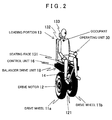
- FIG. 2 exemplifies an external configuration of the vehicle according to the first embodiment.
- the vehicle is provided with two coaxially arranged drive wheels 11a and 11b. Both of the drive wheels 11a and 11b are respectively driven by a drive motor 12.
- a loading portion 13 (seat) to be loaded with luggage or a rider as a weight body is arranged on the upper side of the drive wheels 11a and 11b (both the drive wheels 11a and 11b will be referred to as drive wheels 11, hereinafter) and the drive motor 12.
- the loading portion 13 is composed of a seating face 131 on which a driver is seated, a seat back 132, and a headrest 133.
- the loading portion 13 is supported by a support member 14 fixed to a drive motor housing 121 that contains the drive motor 12, and structured so as to be movable by an unshown drive mechanism (a seat drive actuator 63 to be described later) relative to the support member 14 or a balancer drive unit 18.
- a seat drive actuator 63 to be described later
- An operating unit 30 is arranged on the left side of the loading portion 13.
- the operating unit 30 is operated by the driver to command operations such as acceleration, deceleration, turning, rotation, stop, and braking of the inverted pendulum vehicle.
- the operating unit 30 in the first embodiment is fixed to the seating face 131, the operating unit 30 may be formed with a remote controller through wired or wireless connection. Alternatively, an armrest may be provided to allow the operating unit 30 to be arranged on the upper side thereof.
- the driving data acquiring unit may be composed of, for example, reading means for reading the driving data from various storage media such as semiconductor memory and/or communication control means for acquiring the driving data from outside through wireless communication.
- FIG. 2 shows a case in which the loading portion 13 is loaded with a person.
- the present invention is not necessarily limited to the case of a vehicle driven by a person. There may be a case in which the vehicle loaded only with luggage is driven and stopped by remote control from outside, a case in which the vehicle loaded only with luggage is driven and stopped according to the driving data, and a case in which the vehicle is driven and stopped unloaded.
- the acceleration, deceleration, and the like are controlled based on operation signals output by operating the operating unit 30.
- the control may be selectable to the attitude control and driving control of the vehicle in response to the longitudinal tilt angle that is changed by the driver along with the forward tilting moment with respect to the vehicle. In the case that the attitude control and driving control are performed based on the tilt moment applied by the driver, the attitude control according to the first embodiment is not performed.
- the seating face 131 of the loading portion 13 is arranged with load meters 51 a to 51e that are not shown and to be described later.
- a control unit 16 is arranged between the loading portion 13 and the drive wheels 11.
- the control unit 16 is installed on the lower surface of the seating face 131 of the loading portion 13.
- the control unit 16 may be installed on the support member 14.
- the balancer drive unit (balancer and balancer drive actuator) 18 according to the first embodiment is arranged at the lower portion of the control unit 16.
- the balancer drive unit 18 is arranged in the position between the both drive wheels 11 substantially in the center thereof.
- FIG. 3 shows a configuration of the control unit 16.
- the control unit 16 is provided with a control ECU (electronic control unit) 20 for performing various kinds of control such as the vehicle running and attitude control and the center-of-gravity displacement control in the first embodiment.
- the operating unit 30, a sensor 40 for running and attitude control, a sensor 50 for center-of-gravity displacement control, an actuator 60, and other devices such as a battery are electrically connected to the control ECU 20.
- the battery supplies power to the drive motor 12 and a balancer drive actuator 62.
- the battery also supplies a low voltage power source for control to the control ECU 20.
- the control ECU 20 is composed of a computer system provided with a ROM containing data and various programs such as a running control program, an attitude control program, and a center-of-gravity displacement control program, a RAM for use as a work area, external storage devices, interfaces, and others.
- the control ECU 20 is provided with a vehicle body basic control system 21 for performing the running and attitude control, and a center-of-gravity displacement control system 22.
- the center-of-gravity displacement control system 22 is provided with a disturbance observer 23 and a center-of-gravity displacement calculation portion 24 that calculate the torque values as physical quantities corresponding to the amount of displacement of an actual center of gravity of the vehicle from the reference axis.
- the center-of-gravity displacement control system 22 calculates and supplies a correction value for a basic target value in vehicle body tilt angle control and command values to the balancer drive actuator 62 and the seat drive actuator 63, respectively, to align the actual center of gravity of the vehicle with the designed center of gravity of the vehicle.
- the sensor 40 for running and attitude control is provided with a running speed meter (wheel rotation meter) 41 for detecting a vehicle speed (wheel rotation angle) and a vehicle body tilt angle meter (angular velocity meter) 42 for detecting a vehicle body tilt angle (tilt angular velocity). Detection values of the sensor 40 for running and attitude control are supplied to the vehicle body basic control system 21 and also to the disturbance observer 23 and the center-of-gravity displacement calculation portion 24 of the center-of-gravity displacement control system 22.
- the sensor 50 for center-of-gravity displacement control is provided with a plurality of load meters 51 (load distribution meter), and each load data value (seat load distribution) detected by each of the seat load meters 51 is supplied to the center-of-gravity displacement calculation portion 24.
- FIG. 4 shows an arrangement of the load meters 51.
- the load meters 51 are arranged at five places of four corners and center of the seating face 131 (seat).
- Each of the load meters 51 is arranged in the position lower than the seat structure (seating face 131), and configured so as to be capable of measurement even if the rider leans backward.
- the luggage loaded on the seat can also be measured.
- the load applied by a person pushing the seat (seating face 131) from outside can be measured.
- the load meters 51 in the first embodiment can provide a complete measurement under an upright and stationary condition.
- the center-of-gravity displacement calculation portion 24 calculates the position of the actual center of gravity and the total weight of the vehicle body and the loaded body from the vehicle body weight, the vehicle body center-of-gravity position, and the detection values of the load meters 51 a to 51e.
- load meters 51 Although at least only two of the load meters 51 are required to identify a one-dimensional position (in the longitudinal direction of the vehicle) of the center of gravity, installation of more load meters (five load meters in the first embodiment) realizes a fail-safe function (causing no problem even if one load meter has broken).
- sensors that can also measure tensile load may be used as load meters 51. This allows the measurement to be made even if the center of gravity lies outside of the polygon formed by the sensors.
- triaxial sensors tension-compression, and shear forces
- a torsional torque meter may be used to measure a torsional torque applied to the loading portion 13, thus measuring the displacement of the center of gravity.
- the actuator 60 is provided with a tire rotation actuator 61 for driving the drive wheels 11 according to the command value supplied from the vehicle body basic control system 21, the balancer drive actuator 62 for moving the balancer according to the command value supplied from the center-of-gravity displacement control system 22, and the seat drive actuator 63 for moving the loading portion 13 forward and backward according to the command value supplied in the same way.
- FIG. 5 is a flow chart showing contents of the center-of-gravity displacement control.
- this center-of-gravity displacement control first the amount of displacement of the actual center of gravity of the vehicle is obtained as a torque value that is a physical quantity (steps 11 to 17), and subsequently, the displaced actual center of gravity of the vehicle is moved so as to lie on the reference axis based on the torque value obtained (steps 18 to 27). The contents of each process will be described below.
- the amount of displacement of the actual center of gravity of the vehicle and the torque value generated thereby are calculated from the measured values by the load meters 51 and those for the attitude control, and through the steps 14 to 16, the torque value due to disturbance is estimated using the disturbance observer 23. Note that both of the above processes of the steps are executed in parallel for the calculation and the estimation of the torque values.
- the load distribution is measured by making a measurement with the five load meters 51a to 51e arranged at the seating face 131, and supplied to the center-of-gravity displacement control system 22 of the control ECU 20 (step 11).
- the center-of-gravity displacement control system 22 calculates the forces (vertical component and horizontal component) and the torque acting on the loading portion 13 based on the load distribution data (measured values by the respective load meters 51) obtained (step 12).
- the center-of-gravity displacement control system 22 evaluates the amount of effect of the displacement of the center of gravity by using the vehicle body tilt angle ⁇ 1 and a translational acceleration a obtained by the sensor 40 for running and attitude control (step 13). That is, the center-of-gravity displacement control system 22 calculates the weight m H of the weight body A, the displacement ⁇ H of the center of gravity of the weight body A from the reference axis n, and the height h H of the center of gravity of the weight body A relative to the mounting position of the load meters 51 as information on the weight body A (rider, luggage, or the like) loaded on the loading portion 13 (seating face 131), based on the following six formulae 2 representing the equilibrium of the forces (normal force and transverse force) and the torque.
- FIG. 6 shows a state of equilibrium of the forces (including inertial forces) and the moment of the weight body A acting on the loading portion 13.
- X (k) represents the mounting position of the load meter (k) relative to the center point of the vehicle body
- m s represents the mass of the loading portion 13
- ⁇ s represents the position of the center of gravity of the loading portion 13 relative to the center point of the vehicle body
- h s represents the height of center of gravity of the loading portion 13
- g represents the gravitational acceleration.
- the translational acceleration a is calculated from the vehicle speed detected by the running speed meter 41
- the position of the center of gravity of the weight body A can be estimated based on the above-shown formulae 2 by using the angle data ⁇ 1 obtained by the vehicle body tilt angle meter 42 used for attitude control, even while the loading portion 13 is tilted.
- the position of the center of gravity of the weight body A can be evaluated by referring to the translational acceleration a obtained by the running speed meter 41 (tire rotational angle sensor) used for attitude control, even during acceleration or deceleration.
- the center-of-gravity displacement control system 22 calculates the torque T applied by the weight A to the loading portion 13, from the following formula 3.
- Is is a distance from the axle of the drive wheels 11 to the load meters 51.
- T m H ⁇ g ⁇ H - m H ⁇ h H + l S ⁇ ⁇ ⁇ H
- the disturbance observer 23 the disturbance, that is, the amount of effect (torque value) of the displacement of the center of gravity of the loading portion 13 is estimated based on the motion of the vehicle body and the results of the attitude control (time history) (steps 14 to 16).
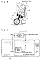
- FIG. 7 conceptually shows a state of disturbance estimation by the disturbance observer 23.
- the controller corresponds to the vehicle body basic control system 21, and the actual controlled object corresponds to the tire rotation actuator 61 (object of control) and the whole vehicle (object subjected to disturbance).
- the disturbance observer 23 is composed of a controlled object model and an estimator.
- the controlled object model is a theoretical model based on the designed center of gravity of the vehicle and corresponds to the actual controlled object that is a controlled object in reality.
- An input u (actually a vector as shown in FIG. 7 , however, the vector notation is omitted for notational convenience; the same applies below) from the controller is introduced into both the actual controlled object and the controlled object model. Then, an output y ⁇ (notation differs from that of the drawing, similarly to the vector; the same applies below) is produced as theoretical values from the controlled object model. On the other hand, an output y (measured values such as the tilt angle 0) is produced from the actual controlled object in response to the state in which a disturbance d is applied.
- the estimator calculates an estimated value d ⁇ of disturbance acting on the loading portion 13 according to the following formulae 4.
- the estimation in the estimator (formulae 4) assumes the effect of the displacement of the actual center of gravity of the vehicle as a part of the disturbance.
- a minimal order observer is used to reduce calculation time (a full-order observer can be used if robustness is given a higher priority).
- the estimated speed is determined by a feedback gain L of the disturbance observer 23.
- L of the disturbance observer 23 is a certain amount of time is required for the estimation.
- FIG. 8 illustrates a mechanical model taking into account the movement of the actual center of gravity of the vehicle due to the movement of the rider. The symbols shown in FIG. 8 are described as follows.
- formula 5 is expressed in the form of system state equations as shown by formulae 7 so that the disturbance observer 23 can easily process the disturbance due to movement of the weight body A (rider).
- the values in the formulae 7 are as shown in formulae 8, respectively, where I represents an identity matrix.
- the disturbance observer 23 obtains the input u (torque command value to the tire rotation actuator 61 shown in FIG. 3 ) and the output y (detection values [speed and vehicle body tilt angle] of the sensor 40 for running and attitude control shown in the same figure) in the attitude control (step 14). Then, the disturbance observer 23 calculates the estimated value d ⁇ of the disturbance acting on the loading portion 13 by solving the above-shown formulae 4 using the estimator (step 15). Note that, although the disturbance observer 23 uses the minimal order observer, the full-order observer can be used for the estimation.
- the estimated value d ⁇ of the disturbance calculated is represented by formula 9.
- the estimated disturbance d ⁇ is calculated as a sum of three disturbances. Although each of the disturbances is not obtained individually, being merely a value for mathematical expression, the total value of d ⁇ is calculated because all of the three disturbances contribute to the tilting motion of the vehicle.
- the first disturbance is the amount of effect of the displacement of the center of gravity due to the movement of the rider, being represented by the first term (m H g ⁇ H ) of the right-hand side of the formula 9.
- the second disturbance is the effect of the inertial force due to a quick movement of the weight body A (rider), being represented by the second term (-m H l H ( ⁇ ) H , where ( ⁇ ) represents ⁇ with double dots over it) of the right-hand side.
- the third disturbance includes other disturbances (such as pushing the vehicle body from outside), being represented by the third term ( ⁇ e ) of the right-hand side.
- the center-of-gravity displacement control in the first embodiment performs the control against the amount of the disturbance as a whole, the control can be performed without knowing the components of the estimated disturbance d ⁇ . However, knowing each of the components enables the following uses.
- each of the components is extracted and evaluated against the estimated disturbance value d ⁇ calculated (step 16), in the first embodiment.
- the displacement of the center of gravity of the weigh body A is steady and in the low-frequency range
- the inertial force due to the movement of the center of gravity is nonsteady and in the medium-frequency range (at a speed at which a person can move)
- other disturbances are nonsteady and in the high-frequency range.
- the low-frequency component is extracted by a low-pass filter and assumed to be the effect of the displacement of the center of gravity.
- the effect of the inertial force is also extracted by obtaining a component in a certain frequency band (approximately 1 Hz to 10 Hz).
- the decomposition into the components may be performed by using the information obtained from the load meters on the seat, or the like.
- the center-of-gravity displacement control system 22 After obtaining, according to the above-described processing, the torque value that has been calculated based on the direct measurement of the load distribution with the load meters 51 and the torque value that has been estimated by the disturbance observer 23, the center-of-gravity displacement control system 22 compares the two data values, and determines the amount of effect of the corresponding displacement of the center of gravity (step 17). That is, the center-of-gravity displacement control system 22 determines the torque to be used for correction, to be described later, of the displacement of the actual center of gravity of the vehicle (steps 18 to 27) based on both of the torque values obtained.
- Tk the torque value calculated based on the direct measurement of the load distribution
- Tg the torque value estimated by the disturbance observer 23
- the torque value Tk calculated by using the load meters 51 (steps 11 to 13) and the torque value Tg estimated by the disturbance observer 23 (steps 14 to 16) have upper limit values f1 and f2, respectively, for frequencies within which the evaluation is possible. That is, the torque value Tk by the load meters 51 has the upper limit f1 determined by hardware limitations such as natural frequency and response performance, and the torque value Tg by the disturbance observer 23 has the upper limit f2 for stability (robustness) determined from the estimated speed (pole).
- the weightings based on the respective frequency components for the frequency components of both of the torques Tk and Tg are defined based on the upper limits f1 and f2 as follows.
- FIG. 9 shows the weightings for respective frequency components applied to both of the torque values calculated.
- one of the both torque values Tk and Tg is used as a failure determination indicator for the other value. That is, the difference between the both values is evaluated for each frequency component, and if the difference is large, one that is judged, through detailed examination, to have a higher possibility of error is regarded as failed. If one is determined as failed, the other torque value is used with a weighting of 1.
- the center-of-gravity displacement control system 22 distributes the amount of effect Tf of the corresponding displacement of the center of gravity, to respective elements (center-of-gravity displacement correction mechanisms [systems] S1, S2, and S3) (step 18).
- the center-of-gravity displacement correction mechanisms S1, S2, and S3 correspond to the correction of main body reference angle (C), the center-of-gravity correction by using an added weight (balancer) (D), and the center-of-gravity correction by deformation of vehicle body (seat movement) (E), respectively, that are outlined in FIGS. 1C, 1D and 1E .
- Each of the correction mechanisms (systems) S1, S2, and S3 has a frequency range suitable for using the mechanism with respect to each frequency component.
- the correction mechanism S2 by movement of balancer has an upper limit f3
- the correction mechanism S3 by movement of seat has an upper limit f4. Therefore, the center-of-gravity displacement control system 22 distributes the torque value Tf determined in the step 17 as torque values to be used by the respective correction mechanisms (systems) depending on the frequency components of the torque value Tf.
- FIG. 10 shows the weightings for respective frequencies used for distributing the torque value Tf to the center-of-gravity displacement correction mechanisms (systems) S1, S2, and S3.
- the weightings used for distributing the torque Tf in accordance with the characteristics of the respective center-of-gravity displacement correction mechanisms (systems) are determined as follows.
- the correction mechanism S2 by movement of balancer may be mainly used, and if a performance beyond the capability limit thereof is required, the correction mechanism S3 by movement of seat may be used as a substitute or supplement. Then, if a performance even exceeding the limit of the correction mechanism S3 by movement of seat is required, the correction mechanism S1 by main body tilting may be used as another substitute or supplement.
- the limits of the correction mechanisms (systems) S1 to S3 are respectively described as follows.
- the entire torque value of the corresponding frequency may be distributed to each of the correction mechanisms; that is, the torque value in the low-frequency range may be distributed to the correction mechanism S3 by movement of seat, the torque value in the high-frequency range may be distributed to the correction mechanism S2 by movement of balancer, and the torque value in the medium-frequency range may be distributed to the correction mechanism S1 by main body tilting.
- any of the three correction mechanisms (systems) S1 to S3 may be used as a substitute for fail-safe purposes. That is, one of the three control mechanisms, for example the S2, may be determined as a main correction mechanism that is normally used, and the remaining two mechanisms are used as complements in the case of failure of the main control mechanism. In this case, as the substitute, the mechanism whose applicable frequency is nearer to that of the main control mechanism is chosen from the two alternatives.
- the center-of-gravity displacement control system 22 uses each of the correction mechanisms (systems) to correct the displacement of the center of gravity (steps 19 to 21, steps 22 to 24, and steps 25 to 27).
- FIG. 11 shows methods for correcting the displacement of the center of gravity by the respective correction mechanisms (systems) S1 to S3.
- FIG. 11 shows examples of the cases in which the entire torque value Tf determined is distributed to each one of the respective correction mechanisms (systems), each example illustrating the case in which a single correction mechanism (system) moves the actual center of gravity P of the vehicle so as to lie on the reference axis n. Note that, in the case in which the torque value Tf is distributed respectively to the correction mechanisms (systems) S 1 to S3, the actual center of gravity P of the vehicle is moved so as to lie on the reference axis by overall operation of all of the correction mechanisms (systems) with the distributed torques.
- the center-of-gravity displacement control system 22 calculates the main body tilt angle (correction value ⁇ 1 * ,1 for basic target value ⁇ 1 * ,0 ) to eliminate the effect of displacement of the center of gravity according to the following formula 10 as shown in FIG. 11A , and then supplies the calculation result to the vehicle body basic control system 21 (step 19).
- the basic target value ⁇ 1 * ,0 is a target tilt angle that is set on the assumption that the overall center of gravity lies on the vehicle body axis
- the correction value ⁇ 1 * ,1 for the basic target value is a value for correcting the target tilt angle by taking the effect of the displacement of the center of gravity into account.
- the vehicle body basic control system 21 corrects the target value of the attitude control (servo) from the basic target value ⁇ 1 * ,0 to a corrected target value ⁇ 1 * according to the following formula 11 (step 20).
- m 1 is a total mass of the main body and the rider.
- the vehicle body basic control system 21 calculates the drive torque (total of two wheels) ⁇ W of the drive motor 12 according to formula 12, and then by supplying the drive torque ⁇ W as a command value to the tire rotation actuator 61, tilts the main body (loading portion 13) so that the actual center of gravity of the vehicle moves so as to lie on the reference axis n (vertical line in the figure) (step 21).
- ⁇ W - K ⁇ ⁇ 1 - ⁇ 1 * - ...
- the existing attitude control system can be used without modification to respond to the displacement of the center of gravity.
- the correction mechanism S2 by movement of balancer controls the position of the mass (balancer) added to the vehicle body so that the overall center of gravity lies on the reference axis n, as shown in FIG. 11B . That is, the center-of-gravity displacement control system 22 calculates the position ⁇ * 2 of the balancer to eliminate the effect of displacement of the center of gravity according to formula 13 (step 22). Note that m 2 is a mass of the balancer.
- the center-of-gravity displacement control system 22 sets the target value of the balancer control to the calculated position (step 23), and then drives the balancer so that the center of gravity moves so as to lie on the reference line (vertical line in the figure) (step 24). That is, the center-of-gravity displacement control system 22 calculates a balancer drive force S B according to the following formula 14 in which the current balancer position is denoted as ⁇ , and then supplies the balancer drive force S B as a command value to the balancer drive actuator 62. Hereby, the balancer is moved to the determined position to move the actual center of gravity of the vehicle so as to lie on the reference axis n (vertical line in the figure).
- the correction mechanism S3 by movement of seat translates the loading portion 13 forward and backward so that the overall center of gravity lies on the reference axis n, as shown in FIG. 11C .
- the center-of-gravity displacement control system 22 calculates the position ⁇ * 3 of the seat (loading portion 13) to eliminate the effect of displacement of the center of gravity according to formula 15 (step 25).
- m c is a total mass of the loading portion 13 and the weight body A (for example, the rider).
- the mass of the weight body A is obtained from the measured values by the load meters 51 in the first embodiment. However, if load meters are not used, the value of the model weight that has been assumed in the case of determination of the designed center of gravity of the vehicle is used.
- ⁇ * 3 - ⁇ 1 , e / m c ⁇ g
- the center-of-gravity displacement control system 22 sets the target value of the seat control to the calculated seat position ⁇ * 3 (step 26), and then moves the seat so that the center of gravity moves so as to lie on the reference line (vertical line in the figure) (step 27). That is, the center-of-gravity displacement control system 22 calculates a seat (loading portion 13) drive force S S according to the following formula 16 in which the seat position before movement relative to the center point of the vehicle body is denoted as ⁇ 3 , and then supplies the seat drive force S S as a command value to the seat drive actuator 63.
- the loading portion 13 is moved to the determined position to move the actual center of gravity of the vehicle so as to lie on the reference axis n (vertical line in the figure).
- the amount of correction has a quantitative limit determined by the maximum travel, the value of the limit is larger than that of the correction by balancer movement. Note that it is possible to accelerate the wheels forward at the same time when the seat is accelerated backward so that the rider does not feel an inertial force.
- the seat position ⁇ * 3 is given as the correction value.
- the present invention is not limited to the embodiment described above, but can be subjected to various modifications within the scope of what is described in the claims.
- the loading portion 13 is translated as a method of deforming the vehicle body for correcting the displacement of the actual center of gravity of the vehicle.
- the vehicle body may be deformed by any other mechanism.
- a part of the vehicle may be tilted to correct the displacement of the actual center of gravity of the vehicle, as shown in FIG. 12A .
- the portion on the upper side of the connection with the axle may be translated, as shown in FIG. 12B .
- the vehicle has been described as having two drive wheels arranged on one axle.
- the present invention can be applied to a vehicle driven with one drive wheel keeping the balance in the fore-and-aft and right-and-left directions.
- FIG. 13 shows cases in each the amount of displacement (torque value) in the right-and-left direction (lateral direction) is calculated, and also shows the mechanisms (systems) for correcting the displacement in response to the calculated torque values, corresponding to FIGS. 1 and 11 .
- FIG. 13A corresponding to FIG. 1A , shows the case in which the position of the center of gravity and the weight of the rider portion are calculated from the load distribution measured by the load meters 51a to 51e arranged at the seating face 131.
- FIG. 13 describes the case of the displacement in the right-and-left direction, a case is also obviously included in which both displacements in the fore-and-aft and right-and-left directions are calculated and corrected.
- FIG. 13B shows the case in which the amount of displacement is estimated based on the result of control (history) is estimated.
- the disturbance observer 23 estimates the displacement of the center of gravity based on the history of change in attitude of the vehicle body and of torque input. That is, if the vehicle body is going to tilt to the right or left (a tilting torque is applied) even though the tilt angle of the reference axis coincides with the reference angle relative to the reference axis (the control assumes no tilt), the actual center of gravity of the vehicle is considered to be displaced to the right or left from the designed center of gravity of the vehicle. Therefore, the amount of displacement is estimated, for example, as a disturbance torque by the disturbance observer. Note that this case is applied to the one-wheeled vehicle because the vehicle needs to be actually tilted to the right and left.
- the torque values calculated as shown in FIGS. 13A and 13B are determined based on the weightings depending on the frequency in the same manner as the step 17 described above. Also, the torque value determined depending on the frequency is distributed depending of the frequency characteristics of the respective displacement correction mechanisms (systems) in the same manner as the step 18 described above.
- FIGS. 13C to 13E show the displacement correction mechanisms (systems) corresponding to FIGS. 1C to 1E , and FIGS. 11A to 11C , respectively. That is, as shown in FIG. 13C , the main body reference angle in the right-and-left direction is corrected corresponding to the distributed torque value. In addition, as shown in FIG. 13D , the balancer is moved in the right-and-left direction corresponding to the distributed torque value. Furthermore, as shown in FIG. 13E , the seat is moved in the right-and-left direction corresponding to the distributed torque value.
- the completion of getting on or off the vehicle can be estimated from history of the displacement of the center of gravity.
- the center of gravity can be intentionally displaced when a start of getting on or off is detected, thus preventing the vehicle from falling due to an extreme displacement of the center of gravity.
- the qualitative tendency of the controlled object such as frequently moving, not moving, light-weighted, or absent, can be known.
- the body weight and body shape of a person can be entered as values for reference for failure check regarding the weight and the amount of displacement of the center of gravity, and as initial values of estimation.
- the parameters for riders and the operation history can be stored as values for reference for failure check and as initial values of estimation.
- the amount of displacement of the actual center of gravity of the vehicle that is calculated in the embodiment described above may be used as an input to the operation system of the vehicle.
- the low-frequency component can be judged to be an input from the rider, and the high-frequency component can be subjected to suppression control as a disturbance.
- the output may be produced (power-assisted) by multiplying the torque due to the actual displacement of the center of gravity by a gain, or a dead zone may be provided in the vicinity of the zero point.
- a preferred embodiment of a vehicle, a characteristic value estimating device, and a loaded article determination device will be described in detail below with reference to FIGS. 14 to 24 .
- the characteristic value estimating device and the loaded article determination device will be explained taking an example of the vehicle controlling the attitude of itself that enables to achieve the attitude control suitable for the state of the weight body loaded on the vehicle, by correcting the control parameters through estimation of the actual mechanical characteristic values and through use of the estimated the actual mechanical characteristic values.
- FIG. 14 shows an outline of control system characteristic value correction processing according to the second embodiment that corrects the control system characteristic values to optimal values in accordance with the actual weight body.
- controlled target object the portion of the vehicle that is tilted for balancing.
- loaded article corresponds to a person, luggage, an animal, etc., referring to everything that gets on the vehicle from outside and meaning a "weight body.”
- the portion of the "controlled target object” excluding the “loaded article” is referred to as the "vehicle body.”
- the actual mechanical characteristic values of the entire controlled target object including the loaded article on the current vehicle are obtained by direct measurement with measuring instruments and/or estimation based on results of control (history) (sensing). Then, as the reaction shown in FIGS. 14C and 14D , the control system characteristic values in the attitude control system are corrected based on the estimated mechanical characteristic values and used for control.
- FIG. 14A shows a method for directly measuring the mechanical characteristic values of the loaded article with measuring instruments. That is, a weighing scale (load meter) and a sitting height meter are arranged under the loading portion (seat) and on the seat back, respectively, and the weight and the sitting height of the loaded article are measured. The mechanical characteristic values of the loaded article are estimated, and then the mechanical characteristic values of the entire controlled target object are calculated (the characteristic values of the vehicle body are already known).
- FIG 14B shows a case in which the mechanical characteristic values are estimated by, for example, a disturbance observer, based on the history of attitude change and torque input of the controlled target object. That is, if an attitude change, for example a tilting up, of the vehicle body (controlled target object) is too late or too early for a given torque (torque input), it should be considered that the weight or the position of center of gravity of the loaded article has a larger or higher value, or a smaller or lower value, respectively, than an assumed value.
- the effect as described above is estimated by the disturbance observer to estimate the mechanical characteristic values of the entire controlled target object.
- FIG. 14C shows a case in which the control parameters are corrected.
- the control system characteristic values such as a feedback gain in the attitude control system are corrected based on the estimated mechanical characteristic values.
- either of the two methods may be used, or both of the two may be used.
- the control parameters are calculated using a characteristics invariance parameter calculation for an initial predetermined time period after a change in the mechanical characteristic values has been detected, and calculated using a characteristics optimization parameter calculation after the predetermined time period has passed.
- FIG. 14D shows an adjustment of the control system characteristic values with a weight.
- the control system characteristic values are brought close to the reference values. For example, when the rider has lifted the luggage from the foot level onto the seat or raised an arm, the position of the weight is brought down to adjust the position of the center of gravity of the controlled target object and also to reduce the moment of inertia, thus bringing the control system characteristic values close to designed values.
- FIG. 15 is an example showing an external configuration of the vehicle according to the second embodiment.
- the vehicle is provided with two coaxially arranged drive wheels 11a and 11b. Both of the drive wheels 11a and 11b are respectively driven by a drive motor 12.
- a loading portion 13 (seat) to be loaded with luggage or the rider serving as the weight body is arranged on the upper side of the drive wheels 11a and 11b (both the drive wheels 11a and 11b will be referred to as drive wheels 11, hereinafter) and the drive motor 12.
- the loading portion 13 is composed of a seating face 131 on which a driver is seated, a seat back 132, and a headrest 133.
- the loading portion 13 is supported by a support member 14 fixed to a drive motor housing 121 that contains the drive motor 12.
- An operating unit 30 is arranged on the left side of the loading portion 13.
- the operating unit 30 is operated by the driver to command operations such as acceleration, deceleration, turning, rotation, stop, and braking of the vehicle.
- the operating unit 30 in the second embodiment is fixed to the seating face 131, the operating unit 30 may be formed with a remote controller through wired or wireless connection. Alternatively, an armrest may be provided to allow the operating unit 30 to be arranged on the upper side thereof.
- the driving data acquiring unit may be composed of, for example, reading means for reading the driving data from various storage media such as semiconductor memory and/or communication control means that acquires the driving data from outside through wireless communication.
- FIG. 15 shows a case in which the loading portion 13 is loaded with a person.
- the present invention is not necessarily limited to the case of a vehicle driven by a person. There may be a case in which the vehicle loaded only with luggage is driven and stopped by remote control from outside, a case in which the vehicle loaded only with luggage is driven and stopped according to the driving data, and a case in which the vehicle is driven and stopped unloaded.
- the acceleration, deceleration, and the like are controlled based on operation signals output by operating the operating unit 30.
- the control may be selectable to the attitude control and driving control of the vehicle in response to the longitudinal tilt angle that is changed by the driver along with the forward tilting moment with respect to the vehicle.
- the attitude control and driving control are performed based on the tilt moment applied by the driver, the attitude control according to the second embodiment is not performed.
- the lower side of the loading portion 13 (the back side of the seating face 131) is arranged with a load meter 51 that is not shown and to be described later.
- the back face of the loading portion (the rear surface or inside of the seat back) is arranged with a weight 134.
- the weight 134 is configured so as to be movable in the up-and-down direction by a weight drive actuator 62 to be described later.
- a control unit 16 is arranged between the loading portion 13 and the drive wheels 11.
- the control unit 16 is installed on the lower surface of the seating face 131 of the loading portion 13.
- the control unit 16 may be installed on the support member 14.
- FIG. 16 shows a configuration of the control unit 16.
- the control unit 16 is provided with a control ECU (electronic control unit) 20 that performs various kinds of control such as the vehicle running and attitude control and the control system characteristic value correction control in the second embodiment.
- the operating unit 30, a sensor 40 for running and attitude control, a sensor 50 for estimation of mechanical characteristic values, an actuator 60, and other devices such as a battery are electrically connected to the control ECU 20.
- the battery supplies power to the drive motor 12, the weight drive actuator 62, the control ECU 20, and others.
- the control ECU 20 is composed of a computer system provided with a ROM containing data and various programs such as the running control program, the attitude control program, and a control system characteristic value correction processing program, a RAM for use as a work area, external storage devices, interfaces, and others.
- the control ECU 20 is provided with the vehicle body basic control system 21 that performs the running and attitude control, and a mechanical characteristic value estimation control system 22.
- the mechanical characteristic value estimation control system 22 estimates the actual mechanical characteristic values of the controlled target object in the attitude control system based on the measured values of the sensor 50 for estimation of mechanical characteristic values and also based on the results of control (history) by using the disturbance observer 23, thus functioning as estimation means.
- the mechanical characteristic value estimation control system 22 supplies corrected values of the control parameters to the vehicle body basic control system 21, and also supplies a command value indicating the amount of movement of the weight 134 ( FIG. 14 ) to the weight drive actuator 62.
- the sensor 40 for running and attitude control is provided with a running speed meter (wheel rotation meter) 41 for detecting a vehicle speed (wheel rotation angle) and a vehicle body tilt angle meter (angular velocity meter) 42 for detecting a vehicle body tilt angle (tilt angular velocity). Detection values of the sensor 40 for running and attitude control are supplied to the vehicle body basic control system 21 and also to the mechanical characteristic value estimation control system 22.
- the sensor 50 for estimation of mechanical characteristic values is provided with the load meter 51 (or a load distribution meter) and a sitting height meter (or a shape measuring device) 52.
- FIG. 17 shows an arrangement of the load meter 51 and the sitting height meter 52.
- the load meter 51 is arranged on the lower side of the loading portion 13, specifically, on the lower surface of the seating face 131, and measures a mass of the loaded article to be supplied to the mechanical characteristic value estimation control system 22.
- the load meter 51 is configured so as to be capable of measuring not only a load of the loaded article arranged on the loading portion, but also a load of the luggage hung on the seat back 132 or the headrest 133 as well as a load of every loaded article arranged at any other location.
- the weight of the vehicle body hereinafter called “vehicle body weight”
- vehicle body center-of-gravity position the position of the center of gravity thereof
- the load meter 51 of the second embodiment measures the mass of the rider using one single-component load meter while the vehicle is running upright at a low speed
- a combination of a main body tilt angle sensor and a translational acceleration sensor used for the attitude control, or a three-component load meter may be used.
- the load can also be measured while the vehicle is tilted or accelerated.
- a plurality of the load meters may be arranged to measure a load distribution for estimating the size of the rider.
- the seat back 132 is provided with the sitting height meter 52 for measuring the sitting height (height) of the loaded article such as the rider.
- the sitting height meter 52 has a plurality of fixed optical sensors arranged in the direction of z-axis (in the direction of height) to discretely measure the sitting height of the rider and supply the measured values to the mechanical characteristic value estimation control system 22 ( FIG. 16 ).
- the sitting height meter 52 may have moving (scanning) optical sensors to perform scanning in the direction of z-axis, whereby the measurement can be made with a high accuracy.
- the fixed optical sensors may be distributed on a plane, or the scanning optical sensors may perform a planar scan to identify the size and shape of the rider for distinguishing the loaded article (person, luggage, or other).
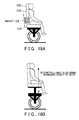
- FIG. 18 shows the weight 134 arranged on the seat back 132.
- the weight 134 is arranged on the seat back 132, and configured so as to be movable in the up-and-down direction.
- the movement in the up-and-down direction is achieved by a variety of methods such as moving with a ball screw or moving on a rail by using a linear motor.
- Moving the weight 134 in the up-and-down direction serves as vehicle body deforming means for changing the position of the center of gravity or the moment of inertia of the vehicle body.
- the position of the center of gravity or the moment of inertia of the vehicle body may be changed by changing the height of the loading portion 13 (controlled target object), as shown in FIG. 18B .
- the position of the center of gravity or the moment of inertia of the vehicle body may also be changed by using weight distribution changing means for changing the weight distribution of the vehicle body.
- the actuator 60 is provided with the tire rotation actuator 61 for driving the drive wheels 11 according to the command value supplied from the vehicle body basic control system 21, and also provided with the weight drive actuator 62 for moving the weight 134 in the up-and-down direction according to the command value supplied from the mechanical characteristic value estimation control system 22.
- FIG. 19 is a flow chart showing contents of the control system characteristic value correction processing.
- the actual mechanical characteristic values of the controlled target object (vehicle body + loaded article) are estimated (estimation process: steps 11 to 17), and subsequently, the control system characteristic values in the attitude control system are corrected based on the mechanical characteristic values obtained (control system characteristic value correction means: steps 18 to 23).
- control system characteristic value correction means steps 18 to 23.
- the weight and the height of the loaded article are measured by the load meter 51 and the sitting height meter 52, respectively, of the sensor 50 for estimation of mechanical characteristic values provided at the loading portion 13, and supplied to the mechanical characteristic value estimation control system 22 (step 11).
- the mechanical characteristic value estimation control system 22 estimates a mass (m 1) , a first moment (m 1 l 1) , and a moment of inertia (I 1 + m 1 l 1 2 ) of the controlled target object as follows (step 12). That is, based on values m H and ⁇ H of the mass and the sitting height, respectively, that have been obtained by the measurement, the mechanical characteristic value estimation control system 22 determines what the loaded article is, for example, by using the following threshold values.
- the mechanical characteristic value estimation control system 22 estimates the height of center of gravity (height from the seating face 131) h H and the moment of inertia (about center of gravity) I H of the loaded article, in accordance with the type of the loaded article discriminated. In this way, by discriminating the loaded article and evaluating it using a formula corresponding to the type thereof, the more accurate mechanical characteristic values can be estimated.
- the mechanical characteristic value estimation control system 22 calculates the mass (m 1 ), the first moment (m 1 l 1 ), and the moment of inertia (I 1 + m 1 l 1 2 ) that are the actual mechanical characteristic values of the controlled target object, from the measured value of the mass m H of the loaded article and the estimated values of the height of center of gravity h H and the moment of inertia I H of the loaded article (step 13).
- the mechanical characteristic value estimation control system 22 obtains the mass m 1 of the controlled target object, the height l 1 from the axis of the drive wheels 11 to the center of gravity, and the moment of inertia I 1 by using the following formulae (a) to (c).
- the mass m H of the loaded article is the measured value in the step 11, and the moment of inertia I H is the moment of inertia I H calculated in the step 12.
- the mechanical characteristic value estimation control system 22 estimates the disturbance (actual mechanical characteristic values) by using the disturbance observer 23, based on the motion of the vehicle body and the results of the attitude control (time history) (steps 14 to 16).
- the mechanical characteristic value estimation control system 22 obtains an input u( ⁇ ) (torque command value to the tire rotation actuator 61 in FIG. 16 ) and an output y( ⁇ ) (detection values [speed and vehicle body tilt angle] of the sensor 40 for running and attitude control in FIG. 16 ) in the attitude control (step 14). Then, the mechanical characteristic value estimation control system 22 estimates the disturbance by using the input u and the output y obtained, and also by using the disturbance observer 23, on the assumption that, if a behavior is different from the behavior that is based on the mechanical characteristic values designed on the basis of the assumed rider, the difference is due to a disturbance based on the fact that an article different from the assumed rider is loaded (step 15). Subsequently, the mechanical characteristic value estimation control system 22 determines the mass, the first moment, and the moment of inertia of the controlled target object from the obtained data (step 16).
- FIG. 20 shows an outline of a flow of estimation of the mechanical characteristic values.
- an estimated disturbance value d( ⁇ ) is calculated by using the disturbance observer (step 31), and vehicle state quantities ⁇ ( ⁇ ) composed of a tire rotational angular acceleration ⁇ W ( ⁇ ), a main body tilt angular acceleration ⁇ 1 ( ⁇ ), and a main body tilt angle ⁇ 1 that are detected (or calculated based on detection values) by the sensor for vehicle control (the sensor 40 for running and attitude control) are determined (step 32).
- vehicle state quantities ⁇ ( ⁇ ) composed of a tire rotational angular acceleration ⁇ W ( ⁇ ), a main body tilt angular acceleration ⁇ 1 ( ⁇ ), and a main body tilt angle ⁇ 1 that are detected (or calculated based on detection values) by the sensor for vehicle control (the sensor 40 for running and attitude control) are determined (step 32).
- the notation differs from that of the drawings for notational convenience, in this specification.
- the mechanical characteristic value estimation control system 22 estimates a variation quantity matrix A from the estimated disturbance value d( ⁇ ) and the vehicle state quantities ⁇ ( ⁇ ) by a least-squares method (step 33), and then estimates respective mechanical characteristic value variations of the main body (controlled target object) from the variation quantity matrix A (step 34). The details of the estimation of the mechanical characteristic value variations will be described below.
- FIG. 21 conceptually shows the state of the disturbance estimation by the disturbance observer 23.
- the controller corresponds to the vehicle body basic control system 21, and the actual controlled object corresponds to the tire rotation actuator 61 (input) and the entire vehicle (controlled target object).
- the disturbance observer 23 is composed of a controlled object model and an estimator.
- the controlled object model is a theoretical model of the attitude control system that uses the designed mechanical characteristic values based on assumed values for the rider.
- the input u( ⁇ ) from the controller is introduced to both the actual controlled object and the controlled object model. Then, an output y( ⁇ ) is produced as theoretical values from the controlled object model. On the other hand, an output is produced from the actual controlled object (controlled target object) as the output y( ⁇ ) (measured values such as tilt angle ⁇ ) in response to the state in which the disturbance d( ⁇ ) is applied.
- the estimated value d( ⁇ ) of the disturbance applied is calculated by the estimator according to the following formulae 17.
- this estimation uses a minimal order observer to reduce calculation time.
- the estimated speed is determined by a feedback gain L of the disturbance observer 23.
- L the disturbance observer 23.
- FIG. 8 the mechanical model of the vehicle attitude control system is shown by FIG. 8 .
- a balancer shown in FIG. 8 is a weight body for performing the attitude control of the vehicle, and moves in the direction perpendicular to the axle and the vehicle center axis, as shown as an example.
- the weight 134 that moves in the up-and-down direction is included in the main body.
- the symbols in FIG. 8 are as described in the
- the mechanical model shown in FIG. 8 is expressed by the linear second-order differential equation of formula 18.
- the values in the formula 18 are as shown in formulae 19, respectively.
- the values of I W,a and I 12,a in the formulae 19 are as follows.
- I W , a I W + m 1 + m 2 + m W ⁇ R W 2
- I 12 I 1 + m 1 ⁇ l 1 2 + I 2 + m 2 ⁇ l 2 2
- the disturbance d( ⁇ ) by the change in the rider parameters is expressed by the following formulae 20.
- the elements ⁇ 1 , ⁇ 1 ( ⁇ ), and ⁇ W ( ⁇ ) of the vehicle state quantities ⁇ ( ⁇ ) are the main body (vehicle body) tilt angle, the main body tilt angular acceleration, and the tire rotational angular acceleration, respectively, as described above.
- formula 18 is expressed in the form of general state equations as shown by formulae 21 so as to be easily handled by the disturbance observer 23.
- the values in the formulae 21 are as shown in formulae 22, respectively, where I represents an identity matrix.
- the disturbance observer 23 obtains the input u (torque command value to the tire rotation actuator 61 shown in FIG. 16 ) and the output y (detection values [speed and vehicle body tilt angle] of the sensor 40 for running and attitude control shown in the same figure) in the attitude control. Then, the disturbance observer 23 calculates the estimated value d( ⁇ ) of the disturbance by solving the above-shown formulae 17 in the estimator ( FIG. 21 ) (step 32). Note that, although the disturbance observer 23 uses the minimal order observer, the full-order observer can be used for the estimation.
- the reliability of the high-frequency component is ensured not by using the disturbance observer 23 for the high-frequency component, but by using the values calculated from measured values of the measuring instruments (the sensor 50 for estimation of mechanical characteristic values) (steps 11 to 13) for the high-frequency component.
- calculation may be simplified by ignoring the correlation in the ⁇ ( ⁇ ), that is, by making the non-diagonal components of the tensor product ⁇ (k) ( ⁇ ) ⁇ (k) ( ⁇ ) to be zero.
- the disturbance observer 23 estimates a mass variation ⁇ m 1 , a first-moment variation ⁇ (m 1 l 1 ), and a moment-of-inertia variation ⁇ (I 1 + m 1 l 1 2 ) as three parameter variation quantities of the main body (controlled target object), as shown by formulae 25 (step 34).
- the first-moment variation ⁇ (m 1 l 1 ) can be estimated (calculated) from any one of three elements ⁇ 23 , ⁇ 12 , and ⁇ 21 of the variation quantity matrix.
- the elements ⁇ 23 , ⁇ 12 , and ⁇ 21 correspond to the state quantities ⁇ 1 , ⁇ 1 ( ⁇ ), and ⁇ W ( ⁇ ), respectively. Consequently, in the second embodiment, a highly accurate value of the first-moment variation ⁇ (m 1 l 1 ) can be calculated by using the formula corresponding to the one with the maximum range of variation within the reference time among the three state quantities ⁇ 1 , ⁇ 1 ( ⁇ ), and ⁇ W ( ⁇ ).
- the mechanical characteristic value estimation control system 22 After estimating the mechanical characteristic values from the measured values of the sensor 50 for estimation of mechanical characteristic values and also estimating the mechanical characteristic values by the disturbance observer 23 through the processing described above, the mechanical characteristic value estimation control system 22 compares the two data to determine the mechanical characteristic values, that is, the mass, the first moment (height of center of gravity), and the moment of inertia of the controlled target object ( FIG. 19 and step 17). Note that, in the explanation below, the mechanical characteristic values estimated from the measured values of the sensor 50 for estimation of mechanical characteristic values are denoted as Pk, and the mechanical characteristic values estimated by the disturbance observer 23 are denoted as Pg.
- the mechanical characteristic values Pk and Pg are estimated by the two methods, and by using the two methods as described in (1) to (4) below, more accurate estimation of the mechanical characteristic value variations is achieved.
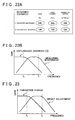
- FIG. 22 shows an example of selective use of the mechanical characteristic values Pk and Pg.
- the weightings are applied depending on the degree of reliability, as shown in FIG. 22A .
- Measuring instruments have a high reliability with respect to the mass (m 1 ), and the disturbance observer has a high reliability with respect to the first moment (m 1 l 1 ). Therefore, as shown in FIG. 22A , the mechanical characteristic values Pk and Pg are used with weightings given as percentages shown below. Note that the percentages for the both values are merely examples, and other percentages can be employed.
- 90% of Pk and 10% of Pg are used.
- 30% of Pk and 70% of Pg are used.
- 50% of Pk and 50% of Pg are used.
- the mechanical characteristic values Pk that are calculated by using the measured values (steps 11 to 13) and the mechanical characteristic values Pg that are estimated by the disturbance observer 23 (steps 14 to 16) have upper limit frequencies f1 and f2, respectively, below which the evaluation is possible. That is, the mechanical characteristic values Pk have the upper limit f1 determined by hardware limitations such as natural frequency and response performance. On the other hand, the mechanical characteristic values Pg by the disturbance observer 23 have the upper limit f2 for stability (robustness) determined from the estimated speed (pole).
- the weightings based on the respective frequency components are determined for the respective frequency components of the both mechanical characteristic values Pk and Pg, as exemplified in FIG. 22B .
- the disturbance observer cannot perform the estimation with high accuracy. Consequently, at start of control (during a period from the start of control to a predetermined time T1) or during mild driving (in the case that the rates of change in acceleration and attitude angle are ⁇ 1% or less), a 100% of the mechanical characteristic values Pk based on the measured values are used, and the values thereof are provided as initial values for the disturbance observer. In other cases, the estimation is performed according to (1) or (2) described above.
- a value of either of the mechanical characteristic values Pk or Pg is used as a failure determination indicator for the value of the counterpart thereof. That is, the difference between the both values is evaluated for each frequency component, and if the difference is large, one that is judged, through detailed examination, to have a higher possibility of error is regarded as failed. If one is determined as failed, the other characteristic value is used with a weighting of 1. Note that the values Pk and Pg are always used as fail-safe determination indicators for judgment of failure, independently from (1) to (3) described above.
- the mechanical characteristic value estimation control system 22 After determining the mechanical characteristic value variations (denoted as Pf) to be employed for respective frequency components (step 17), the mechanical characteristic value estimation control system 22 appropriately distributes the corresponding mechanical characteristic value variations Pf to respective corresponding mechanisms (systems) (step 18).
- the respective corresponding mechanisms (systems) refer to the mechanism for correction of the control parameters themselves (hereinafter called “parameter changing system”) and the mechanism for adjustment of the control system characteristic values by the weight (hereinafter called “weight adjustment mechanism”), outlined in FIGS. 14C and 14D , respectively.
- the weight adjustment mechanism is used in the comparatively high frequency range in which the parameter changing system takes a long time to recalculate the control parameters.
- the parameter changing system has an upper limit frequency f4 from the standpoint of calculation time and stability (robustness) whereas the weight adjustment mechanism has an upper limit frequency f3 determined by hardware limitations and also has a necessity of avoiding the fundamental frequency band of the attitude control system for preventing cross coupling with the attitude control system. Therefore, as shown in FIG. 23 , the mechanical characteristic value variations Pf that have been determined in the step 17 are distributed to the parameter changing system and the weight adjustment mechanism, according to the weightings corresponding to the frequency components. Note that the systems in the second embodiment ignore considerably quick variations by cutting off the high-frequency components, as shown in FIG. 23 , because the systems control quasi-steady variations (variations at a lower speed than the characteristic speed of the attitude control system; for example, changes in the order of several seconds) of the mechanical characteristic values.
- the weight adjustment mechanism has a qualitative limitation that the mass cannot be adjusted (increased or decreased), and a quantitative limitation that the mass and the movable travel of the weight are limited. Therefore, the parameter changing system responds to the conditions exceeding the limitations of the weight adjustment mechanism, and makes the corrections.
- the parameter changing system can fail in recalculation of the control parameters; that is, for example, a solution can diverge when solving an implicit equation by an iterative calculation method.
- the weight adjustment mechanism can suffer a hardware failure. Therefore, in the second embodiment, when one system has failed, the other system is used to compensate it.
- the mechanical characteristic value estimation control system 22 After determining the mechanical characteristic value variations Pf to be distributed, the mechanical characteristic value estimation control system 22 corrects the control system characteristic values of the attitude control system by using the parameter changing system and the weight adjustment mechanism (steps 19 and 20, and steps 21 to 23).
- FIG. 24 conceptually shows the correction of the control parameters by the parameter changing system. As shown in FIG. 24 , the control parameters are corrected to those suitable for the conditions of distribution (mass, first moment, and moment of inertia) of the mechanical characteristic value variations Pf.
- the controlled object model for the above is expressed by formula 26 that is further expressed in the form of system state equations as shown by formulae 27 so as to be easily handled.
- the symbols x S ( ⁇ ), u( ⁇ ), M S , C S , and K S shown in the formula 26 are defined as shown in the formulae 19 given above.
- the formula 26 does not include the term P d d( ⁇ ).
- the formulae 27 do not include the term Dd( ⁇ ).
- the mechanical characteristic value estimation control system 22 recalculates the control parameters (feedback gain G) optimal for the distributed mechanical characteristic value variations Pf according to the formula 26 or the formulae 27 shown above (step 19), and introduces the obtained control parameters to the control system (step 20).
- the control parameters for the distributed mechanical characteristic value variations Pf there are two methods to calculate the control parameters for the distributed mechanical characteristic value variations Pf: one is the characteristics optimization parameter calculation, and the other is the characteristics invariance parameter calculation.
- the characteristics optimization parameter calculation obtains the gain G that is optimal for the conditions (distributed mechanical parameter values Pf) by, for example, recalculating the feedback gain G from the first, using an optimal regulator or the like.
- the characteristics invariance parameter calculation calculates the gain G that changes the designed control system characteristics as little as possible.
- the characteristics optimization parameter calculation obtains the gain that is optimal for the conditions, it is a disadvantage that the calculation takes a long time.
- the characteristics invariance parameter calculation has the advantages, for one thing, that a reasonably appropriate gain, though not an optimal gain, can be calculated in a short time, and for another thing, that the detailed adjustment when designing the control system can be used effectively.
- the two control parameter calculation methods are selectively used as follows. That is, the control parameters are tentatively set at first by the characteristics invariance parameter calculation, and finally set to the optimal values after the optimal values are calculated by the characteristics optimization parameter calculation. Note that the gain is changed smoothly through a linear transition of the respective parameters in order to prevent the attitude control from becoming unstable by a sudden change of the gain.
- M ⁇ S M S + ⁇ ⁇ M S
- K ⁇ S K S + ⁇ ⁇ K S
- the mechanical characteristic value estimation control system 22 corrects the feedback gain G so that the pole placement of the closed-loop system (basic characteristics of the feedback control system) is changed as little as possible.
- Formulae 33 represent the condition under which the characteristic equations (formulae 29 and 32, respectively) of the closed-loop system are the same between before and after the change of the control parameters (gain).
- the mechanical characteristic value estimation control system 22 obtains gain correction values ⁇ G K and ⁇ G C from both of the formulae 33.
- a matrix P u is regular, a correct calculation is possible so as to change the gains without any change in the pole placement.
- the matrix P u is not regular, the gains are approximately obtained by least-squares method or the like because there is no gain that completely satisfies the formulae shown above. Because the Pu is generally not regular in the attitude control of a one-wheeled vehicle or a two-wheeled vehicle, the mechanical characteristic value estimation control system 22 according to the second embodiment approximately obtains the gain correction values ⁇ G K and ⁇ G C .
- the stability of the closed-loop system needs to be checked by calculation after the feedback gain G thereof has been corrected by using the calculated gain correction values ⁇ G K and ⁇ G C , and if the check result indicates instability, the correction is not executed so as to continue the attitude control with the feedback gain before correction.
- the mechanical characteristic value estimation control system 22 calculates the positioning of the weight 134 (refer to FIG. 18 ) so as to minimize the difference between the values based on the distributed mechanical characteristic values and the nominal values (control assumed values) (step 21), and sets the calculated position as the target position of the weight (step 22). Then, the mechanical characteristic value estimation control system 22 outputs a command value to the weight drive actuator 62 for moving the weight to the target position. As a result, the weight 134 mounted on the vehicle body is moved to the target position by the weight drive actuator 62, and thus the mechanical characteristic values are brought close to the nominal values (step 23).
- the weight m b (k) is moved in the up-and-down direction by the amount of ⁇ h b (k) to balance out the discrepancies of the actual mechanical characteristic values from the nominal values (control assumed values), where the discrepancies are represented by the first moment ⁇ (m 1 l 1 ) and the (second) moment of inertia ⁇ (I 1 + m 1 l 1 2 ) (relative to axle).
- the formulae 34 assumes the case in which there are N weights arranged so as to be capable of moving up and down independently to each other, where (k) indicates the k-th weight of the N weights, and l b (k) represents the distance from the axle to the reference position of the weight.
- Each weight is moved to the target position by the servo control determined from the formulae 34 shown above (where the movement is slower than the characteristic speed of the existing attitude control system).
- both of the parameters first moment and moment of inertia
- both of the parameters can be adapted by using two of the weights 134.
- the travel distance of the weights and the energy consumption can be reduced.
- either the first moment or the moment of inertia is adjusted by using (a) or (b), respectively, of the formulae 34.
- the other one also generally changes in the direction of improvement along with the adjustment of one of the first moment and the moment of inertia.
- both of the first moment and the moment of inertia are adjusted by using (a) and (b), respectively, of the formulae 34.
- the control with minimum travel distance of the weights 134 or the control with minimum energy consumption is possible, in addition to the adjustment of the both parameters.
- control is also possible by changing the height of the seat, in addition to or instead of moving the weights 134.
- the methods of the mechanical characteristic value estimation and the control system characteristic value correction of the second embodiment can also be applied to the attitude control of the one-wheeled vehicle and to the attitude control in the right-and-left direction of the one-wheeled vehicle or the two-wheeled vehicle.
Landscapes
- Engineering & Computer Science (AREA)
- Mechanical Engineering (AREA)
- Transportation (AREA)
- Aviation & Aerospace Engineering (AREA)
- Chemical & Material Sciences (AREA)
- Combustion & Propulsion (AREA)
- Power Engineering (AREA)
- Radar, Positioning & Navigation (AREA)
- Remote Sensing (AREA)
- Physics & Mathematics (AREA)
- General Physics & Mathematics (AREA)
- Automation & Control Theory (AREA)
- Motorcycle And Bicycle Frame (AREA)
Applications Claiming Priority (4)
| Application Number | Priority Date | Filing Date | Title |
|---|---|---|---|
| JP2006130644A JP2007302061A (ja) | 2006-05-09 | 2006-05-09 | 車両 |
| JP2006162402 | 2006-06-12 | ||
| JP2006162403A JP5013244B2 (ja) | 2006-06-12 | 2006-06-12 | 特性量推定装置及び搭載物判定装置 |
| PCT/JP2007/055201 WO2007129505A1 (ja) | 2006-05-09 | 2007-03-15 | 車両、特性量推定装置及び搭載物判定装置 |
Publications (2)
| Publication Number | Publication Date |
|---|---|
| EP2017172A1 true EP2017172A1 (de) | 2009-01-21 |
| EP2017172A4 EP2017172A4 (de) | 2011-11-02 |
Family
ID=38667615
Family Applications (1)
| Application Number | Title | Priority Date | Filing Date |
|---|---|---|---|
| EP07738651A Withdrawn EP2017172A4 (de) | 2006-05-09 | 2007-03-15 | Fahrzeug, kennwerteschätzungsvorrichtung und vorrichtung zur bestimmung eines geladenen artikels |
Country Status (3)
| Country | Link |
|---|---|
| US (1) | US20100070132A1 (de) |
| EP (1) | EP2017172A4 (de) |
| WO (1) | WO2007129505A1 (de) |
Cited By (9)
| Publication number | Priority date | Publication date | Assignee | Title |
|---|---|---|---|---|
| WO2011106772A1 (en) * | 2010-02-26 | 2011-09-01 | Segway Inc. | Apparatus and methods for control of a vehicle |
| WO2014181170A1 (en) * | 2013-05-07 | 2014-11-13 | Toyota Jidosha Kabushiki Kaisha | Inverted vehicle and control method thereof |
| EP2426566A4 (de) * | 2009-04-28 | 2015-04-29 | Toyota Motor Co Ltd | Steuervorrichtung für ein invertiertes fahrzeug |
| WO2017211829A1 (de) * | 2016-06-06 | 2017-12-14 | Universität Kassel | Einachsiges fahrzeug, steuereinrichtung und verfahren zur steuerung eines derartigen fahrzeugs |
| WO2018096175A1 (fr) * | 2016-11-28 | 2018-05-31 | Universite De Versailles Saint-Quentin-En-Yvelines | Véhicule à gyropode |
| DE102017211838A1 (de) * | 2017-07-11 | 2019-01-17 | Uwe Bernhard | Dynamisch balancierendes Fahrzeug |
| EP3395659A4 (de) * | 2015-12-24 | 2019-08-21 | Jiangsu Tallpic Intelligence Technology Ltd. | Sicheres zweirädriges selbstbalancierendes fahrzeug |
| GB2575505A (en) * | 2018-07-13 | 2020-01-15 | Centaur Robotics Ltd | Mobility aid device and method of manufacturing |
| EP3699066A1 (de) * | 2019-02-20 | 2020-08-26 | Siemens Aktiengesellschaft | Selbstbalancierendes fahrerloses transportfahrzeug |
Families Citing this family (41)
| Publication number | Priority date | Publication date | Assignee | Title |
|---|---|---|---|---|
| CN101821122A (zh) * | 2007-12-27 | 2010-09-01 | 爱考斯研究株式会社 | 车辆 |
| JP4825856B2 (ja) * | 2008-09-12 | 2011-11-30 | トヨタ自動車株式会社 | 移動体、及びその制御方法 |
| EP2332815B1 (de) * | 2008-09-11 | 2013-10-30 | Toyota Jidosha Kabushiki Kaisha | Beweglicher körper und steuerverfahren dafür |
| WO2010035324A1 (ja) * | 2008-09-25 | 2010-04-01 | トヨタ自動車株式会社 | 自走車とその制御装置及び制御方法 |
| WO2010047070A1 (ja) * | 2008-10-22 | 2010-04-29 | 株式会社エクォス・リサーチ | 車両 |
| JP2010100137A (ja) * | 2008-10-22 | 2010-05-06 | Equos Research Co Ltd | 車両 |
| JP2010125969A (ja) * | 2008-11-27 | 2010-06-10 | Toyota Motor Corp | 移動体 |
| CN102362233B (zh) | 2009-01-26 | 2013-11-06 | 爱考斯研究株式会社 | 车辆 |
| JP2010225139A (ja) * | 2009-02-27 | 2010-10-07 | Toshiba Corp | 移動機器 |
| CN102574560B (zh) * | 2009-09-18 | 2014-06-18 | 本田技研工业株式会社 | 倒立摆型移动体 |
| CN102574559B (zh) * | 2009-09-18 | 2014-08-20 | 本田技研工业株式会社 | 倒立摆型移动体 |
| WO2011125119A1 (ja) * | 2010-04-06 | 2011-10-13 | トヨタ自動車株式会社 | 移動体制御装置、その制御方法及び制御プログラム |
| WO2012035739A1 (ja) * | 2010-09-13 | 2012-03-22 | パナソニック株式会社 | 搭乗型移動体及び搭乗型移動体の制御方法 |
| JP5816032B2 (ja) * | 2011-09-09 | 2015-11-17 | 任天堂株式会社 | 入力装置、入力処理プログラム、入力処理方法、入力処理システム |
| US9241851B2 (en) * | 2011-10-03 | 2016-01-26 | University Of South Florida | Hands-free user interface devices |
| US9417151B2 (en) * | 2011-11-28 | 2016-08-16 | The Boeing Company | Center of gravity determination |
| AU2015249084B2 (en) * | 2012-02-09 | 2017-09-07 | Omeo Group Limited | Powered Mobility Device with Tilt Mechanism Having Multiple Pivots |
| AU2013285622A1 (en) * | 2012-02-09 | 2014-07-31 | Kevin Thomas Halsall | Powered mobility device |
| JP5716873B2 (ja) * | 2012-09-18 | 2015-05-13 | 株式会社村田製作所 | 移動体 |
| JP6095436B2 (ja) | 2013-03-27 | 2017-03-15 | 本田技研工業株式会社 | 倒立振子型車両 |
| JP6111119B2 (ja) * | 2013-03-29 | 2017-04-05 | 本田技研工業株式会社 | 倒立振子型車両 |
| JP6062784B2 (ja) * | 2013-03-29 | 2017-01-18 | 本田技研工業株式会社 | 倒立振子型車両 |
| JP6081270B2 (ja) | 2013-03-29 | 2017-02-15 | 本田技研工業株式会社 | 倒立振子型車両 |
| JP6081271B2 (ja) | 2013-03-29 | 2017-02-15 | 本田技研工業株式会社 | 倒立振子型車両 |
| JP6062785B2 (ja) | 2013-03-29 | 2017-01-18 | 本田技研工業株式会社 | 倒立振子型車両 |
| JP6099485B2 (ja) | 2013-05-31 | 2017-03-22 | 本田技研工業株式会社 | 倒立振子型車両 |
| JP6099483B2 (ja) | 2013-05-31 | 2017-03-22 | 本田技研工業株式会社 | 倒立振子型車両 |
| JP6099484B2 (ja) | 2013-05-31 | 2017-03-22 | 本田技研工業株式会社 | 倒立振子型車両 |
| TW201446561A (zh) * | 2013-06-05 | 2014-12-16 | Cal Comp Electronics & Comm Co | 載具 |
| US10015481B2 (en) | 2015-05-05 | 2018-07-03 | Goodrich Corporation | Multi-axis center of mass balancing system for an optical gimbal assembly guided by inertial measurement |
| TWI592320B (zh) * | 2015-05-15 | 2017-07-21 | Jon Chao Hong | 以行動終端控制座椅的控制方法及系統 |
| US10576617B1 (en) * | 2015-08-21 | 2020-03-03 | Boston Incubator Center, LLC | Service robot having movable center of mass |
| US10328836B2 (en) * | 2015-09-23 | 2019-06-25 | Amazon Technologies, Inc. | Actively balanced mobile drive unit |
| US10065667B2 (en) * | 2016-07-26 | 2018-09-04 | Soken, Inc. | Carrier apparatus |
| US11370497B2 (en) | 2016-10-18 | 2022-06-28 | Piaggio Fast Forward, Inc. | Vehicle having non-axial drive and stabilization system |
| US10293676B2 (en) * | 2016-10-18 | 2019-05-21 | Piaggio Fast Forward, Inc. | Vehicle having non-axial drive |
| IT201700114497A1 (it) | 2017-10-11 | 2019-04-11 | Piaggio Fast Forward Inc | Veicolo a due ruote con sistema di stabilizzazione lineare |
| MX2020011467A (es) | 2018-05-01 | 2021-04-13 | Piaggio Fast Forward Inc | Metodo para determinar modelos de comportamiento de un vehiculo autonomo, un vehiculo autonomo, y un metodo de conduccion en un vehiculo autonomo. |
| KR102950992B1 (ko) | 2018-10-22 | 2026-04-09 | 피아지오 패스트 포워드 인코포레이티드 | 변위 장치 조립체와 이를 구비하는 모바일 캐리어 |
| US12023132B2 (en) * | 2020-09-21 | 2024-07-02 | Toyota Motor Engineering & Manufacturing North America, Inc. | Systems and methods for remote vital sign monitoring in a vehicle |
| WO2024054522A1 (en) * | 2022-09-06 | 2024-03-14 | Lai Owen | Dynamic weight shifting for vehicles |
Family Cites Families (31)
| Publication number | Priority date | Publication date | Assignee | Title |
|---|---|---|---|---|
| DE3103961A1 (de) * | 1981-02-02 | 1982-09-02 | Navid 8700 Würzburg Bastani Hessari | Zweiraedriges auto |
| DE3800476A1 (de) * | 1988-01-11 | 1989-07-20 | Anschuetz & Co Gmbh | Verfahren zum stabilisieren eines einachsigen radfahrzeugs und fahrzeug, das nach diesem verfahren stabilisiert ist |
| GB2242173A (en) * | 1989-04-11 | 1991-09-25 | Secretary Trade Ind Brit | Dynamically balanced vehicle |
| US5248007A (en) * | 1989-11-21 | 1993-09-28 | Quest Technologies, Inc. | Electronic control system for stair climbing vehicle |
| JPH06175724A (ja) * | 1992-12-02 | 1994-06-24 | Tsubakimoto Chain Co | 搬送車の走行制御方法 |
| JP3260190B2 (ja) * | 1993-01-08 | 2002-02-25 | 株式会社日立製作所 | 自動車の出力軸トルク推定装置及び車重算出装置 |
| US6543564B1 (en) * | 1994-05-27 | 2003-04-08 | Deka Products Limited Partnership | Balancing personal vehicle |
| US6827163B2 (en) * | 1994-05-27 | 2004-12-07 | Deka Products Limited Partnership | Non-linear control of a balancing vehicle |
| JP2959469B2 (ja) * | 1996-05-24 | 1999-10-06 | 日本電気株式会社 | 搭乗物判別装置 |
| JP3826204B2 (ja) * | 1998-02-27 | 2006-09-27 | 東洋電機製造株式会社 | 電気車の接線力係数推定装置 |
| BR9909721A (pt) * | 1998-04-17 | 2001-05-22 | Tract A Pillar Tractor Co Inc | Veìculo baseado na terra |
| JP2000125406A (ja) * | 1998-10-15 | 2000-04-28 | Kiyoshi Oishi | 電気車制御装置 |
| US6405816B1 (en) * | 1999-06-03 | 2002-06-18 | Deka Products Limited Partnership | Mechanical improvements to a personal vehicle |
| US6302230B1 (en) * | 1999-06-04 | 2001-10-16 | Deka Products Limited Partnership | Personal mobility vehicles and methods |
| JP2001191276A (ja) * | 1999-10-29 | 2001-07-17 | Sony Corp | ロボットシステム、ロボット装置及びその外装 |
| JP2003237665A (ja) * | 2002-02-14 | 2003-08-27 | Sigma Solutions:Kk | 二重反転ホイールを内蔵する自立式二輪走行装置 |
| US6752231B2 (en) * | 2002-09-30 | 2004-06-22 | Hume Ross Gordon Mckenzie | Personal transportation system |
| JP2004129435A (ja) | 2002-10-04 | 2004-04-22 | Sony Corp | 搬送装置、制御方法、及び駆動機構 |
| EP1556944A1 (de) * | 2002-10-29 | 2005-07-27 | Seiko Epson Corporation | Verschiebungskontrollsystem für eine fahrzeugachse |
| JP2004276727A (ja) | 2003-03-14 | 2004-10-07 | Matsushita Electric Works Ltd | 人用移動機器とその制動方法 |
| EP1632428A4 (de) * | 2003-06-12 | 2010-08-25 | Toyota Motor Co Ltd | Koaxiales motorrad |
| JP2005096894A (ja) * | 2003-09-22 | 2005-04-14 | Toyota Industries Corp | 産業車両の走行制御装置 |
| JP4556418B2 (ja) * | 2003-11-04 | 2010-10-06 | トヨタ自動車株式会社 | 走行装置及びその制御方法 |
| EP1529556B1 (de) * | 2003-11-04 | 2013-02-20 | Toyota Jidosha Kabushiki Kaisha | Gerät zum Fahren und zugehöriges Steuerverfahren |
| JP4442319B2 (ja) * | 2004-05-25 | 2010-03-31 | トヨタ自動車株式会社 | 走行装置 |
| JP4572594B2 (ja) * | 2004-06-16 | 2010-11-04 | トヨタ自動車株式会社 | 平行二輪車 |
| JP2006123854A (ja) * | 2004-11-01 | 2006-05-18 | Matsushita Electric Ind Co Ltd | 荷物運搬ロボット |
| CN100557539C (zh) * | 2005-07-26 | 2009-11-04 | 松下电器产业株式会社 | 倒立二轮行走型机器人及其控制方法 |
| JP4291822B2 (ja) * | 2006-02-03 | 2009-07-08 | トヨタ自動車株式会社 | 倒立車輪型の走行体 |
| JP4434186B2 (ja) * | 2006-09-04 | 2010-03-17 | トヨタ自動車株式会社 | 移動体及び移動体の制御方法 |
| JP4470988B2 (ja) * | 2007-10-25 | 2010-06-02 | トヨタ自動車株式会社 | 倒立車輪型移動体、及びその制御方法 |
-
2007
- 2007-03-15 EP EP07738651A patent/EP2017172A4/de not_active Withdrawn
- 2007-03-15 WO PCT/JP2007/055201 patent/WO2007129505A1/ja not_active Ceased
- 2007-05-15 US US12/227,072 patent/US20100070132A1/en not_active Abandoned
Cited By (27)
| Publication number | Priority date | Publication date | Assignee | Title |
|---|---|---|---|---|
| EP2426566A4 (de) * | 2009-04-28 | 2015-04-29 | Toyota Motor Co Ltd | Steuervorrichtung für ein invertiertes fahrzeug |
| US9126497B2 (en) | 2010-02-26 | 2015-09-08 | Segway, Inc. | Apparatus and methods for control of a vehicle |
| CN102822046A (zh) * | 2010-02-26 | 2012-12-12 | 塞格威股份有限公司 | 车辆控制的装置和方法 |
| JP2013521173A (ja) * | 2010-02-26 | 2013-06-10 | セグウェイ・インコーポレイテッド | 車両を制御するための装置及び方法 |
| US8490723B2 (en) | 2010-02-26 | 2013-07-23 | Segway, Inc. | Apparatus and methods for control of a vehicle |
| US8688303B2 (en) | 2010-02-26 | 2014-04-01 | Segway, Inc. | Apparatus and methods for control of a vehicle |
| WO2011106767A3 (en) * | 2010-02-26 | 2011-11-03 | Segway Inc. | Apparatus and methods for control of a vehicle |
| CN102822046B (zh) * | 2010-02-26 | 2015-06-17 | 塞格威股份有限公司 | 车辆控制的装置和方法 |
| JP2015178358A (ja) * | 2010-02-26 | 2015-10-08 | セグウェイ・インコーポレイテッド | 車両を制御するための装置及び方法 |
| WO2011106772A1 (en) * | 2010-02-26 | 2011-09-01 | Segway Inc. | Apparatus and methods for control of a vehicle |
| WO2014181170A1 (en) * | 2013-05-07 | 2014-11-13 | Toyota Jidosha Kabushiki Kaisha | Inverted vehicle and control method thereof |
| US9745004B2 (en) | 2013-05-07 | 2017-08-29 | Toyota Jidosha Kabushiki Kaisha | Inverted vehicle and control method thereof |
| EP3395659A4 (de) * | 2015-12-24 | 2019-08-21 | Jiangsu Tallpic Intelligence Technology Ltd. | Sicheres zweirädriges selbstbalancierendes fahrzeug |
| WO2017211829A1 (de) * | 2016-06-06 | 2017-12-14 | Universität Kassel | Einachsiges fahrzeug, steuereinrichtung und verfahren zur steuerung eines derartigen fahrzeugs |
| FR3059272A1 (fr) * | 2016-11-28 | 2018-06-01 | Universite De Versailles Saint-Quentin-En-Yvelines | Vehicule a gyropode |
| WO2018096175A1 (fr) * | 2016-11-28 | 2018-05-31 | Universite De Versailles Saint-Quentin-En-Yvelines | Véhicule à gyropode |
| DE102017211838A1 (de) * | 2017-07-11 | 2019-01-17 | Uwe Bernhard | Dynamisch balancierendes Fahrzeug |
| DE102017211838B4 (de) | 2017-07-11 | 2023-07-06 | Uwe Bernhard | Dynamisch balancierendes Fahrzeug |
| GB2575505B (en) * | 2018-07-13 | 2022-08-24 | Centaur Robotics Ltd | Mobility aid device and method of manufacturing |
| KR20210063317A (ko) * | 2018-07-13 | 2021-06-01 | 센타우르 로보틱스 리미티드 | 이동 보조 장치 및 제조 방법 |
| WO2020012425A1 (en) * | 2018-07-13 | 2020-01-16 | Centaur Robotics Limited | Mobility aid device and method of manufacturing |
| GB2575505A (en) * | 2018-07-13 | 2020-01-15 | Centaur Robotics Ltd | Mobility aid device and method of manufacturing |
| US11931302B2 (en) | 2018-07-13 | 2024-03-19 | Centaur Robotics Limited | Mobility aid device and method of manufacturing |
| EP3699066A1 (de) * | 2019-02-20 | 2020-08-26 | Siemens Aktiengesellschaft | Selbstbalancierendes fahrerloses transportfahrzeug |
| WO2020169528A1 (de) * | 2019-02-20 | 2020-08-27 | Siemens Aktiengesellschaft | Selbstbalancierendes fahrerloses transportfahrzeug |
| US20220144353A1 (en) * | 2019-02-20 | 2022-05-12 | Siemens Aktiengesellschaft | Self-balancing driverless transport vehicle |
| US11884338B2 (en) * | 2019-02-20 | 2024-01-30 | Körber Supply Chain Logistics Gmbh | Self-balancing driverless transport vehicle |
Also Published As
| Publication number | Publication date |
|---|---|
| US20100070132A1 (en) | 2010-03-18 |
| WO2007129505A1 (ja) | 2007-11-15 |
| EP2017172A4 (de) | 2011-11-02 |
Similar Documents
| Publication | Publication Date | Title |
|---|---|---|
| US20100070132A1 (en) | Vehicle, characteristic value estimating device, and loaded article determination device | |
| CN101437719B (zh) | 车辆、特性量推定装置及搭载物判定装置 | |
| US8589059B2 (en) | Vehicle with inclination estimation | |
| EP2163467A1 (de) | Fahrzeug | |
| EP2045180A1 (de) | Fahrzeug | |
| EP2177425A1 (de) | Fahrzeug | |
| US20100145576A1 (en) | Vehicle | |
| US8352147B2 (en) | Vehicle control device | |
| JP4888778B2 (ja) | 車両 | |
| US8271185B2 (en) | Vehicle | |
| WO2008032587A1 (en) | Vehicle | |
| CN102149597A (zh) | 车辆 | |
| US20230192068A1 (en) | Apparatus for controlling motion of vehicle and method thereof | |
| JP5110009B2 (ja) | 車両 | |
| KR20230105765A (ko) | 차량 운동 제어 장치 및 그 방법 | |
| JP5182657B2 (ja) | 車両 | |
| JP5041205B2 (ja) | 車両 | |
| JP5013244B2 (ja) | 特性量推定装置及び搭載物判定装置 | |
| JP5392027B2 (ja) | 車両 | |
| JP2010006201A (ja) | 車両 | |
| JP5109990B2 (ja) | 車両 | |
| JP5046084B2 (ja) | 車両 | |
| JP4873305B2 (ja) | 車両 | |
| JP2010208531A (ja) | 車両 | |
| JP2009073271A (ja) | 車両 |
Legal Events
| Date | Code | Title | Description |
|---|---|---|---|
| PUAI | Public reference made under article 153(3) epc to a published international application that has entered the european phase |
Free format text: ORIGINAL CODE: 0009012 |
|
| 17P | Request for examination filed |
Effective date: 20081110 |
|
| AK | Designated contracting states |
Kind code of ref document: A1 Designated state(s): AT BE BG CH CY CZ DE DK EE ES FI FR GB GR HU IE IS IT LI LT LU LV MC MT NL PL PT RO SE SI SK TR |
|
| AX | Request for extension of the european patent |
Extension state: AL BA HR MK RS |
|
| A4 | Supplementary search report drawn up and despatched |
Effective date: 20111004 |
|
| RIC1 | Information provided on ipc code assigned before grant |
Ipc: B62D 37/04 20060101ALI20110927BHEP Ipc: G05D 1/08 20060101ALI20110927BHEP Ipc: B62K 3/00 20060101ALI20110927BHEP Ipc: B60L 15/20 20060101ALI20110927BHEP Ipc: B62K 17/00 20060101AFI20110927BHEP |
|
| DAX | Request for extension of the european patent (deleted) | ||
| STAA | Information on the status of an ep patent application or granted ep patent |
Free format text: STATUS: THE APPLICATION IS DEEMED TO BE WITHDRAWN |
|
| 18D | Application deemed to be withdrawn |
Effective date: 20120503 |