EP2017174B1 - Straddle type vehicle - Google Patents
Straddle type vehicle Download PDFInfo
- Publication number
- EP2017174B1 EP2017174B1 EP08252434.9A EP08252434A EP2017174B1 EP 2017174 B1 EP2017174 B1 EP 2017174B1 EP 08252434 A EP08252434 A EP 08252434A EP 2017174 B1 EP2017174 B1 EP 2017174B1
- Authority
- EP
- European Patent Office
- Prior art keywords
- battery
- helmet
- coupler
- housing part
- type vehicle
- Prior art date
- Legal status (The legal status is an assumption and is not a legal conclusion. Google has not performed a legal analysis and makes no representation as to the accuracy of the status listed.)
- Active
Links
Images



Classifications
-
- B—PERFORMING OPERATIONS; TRANSPORTING
- B62—LAND VEHICLES FOR TRAVELLING OTHERWISE THAN ON RAILS
- B62K—CYCLES; CYCLE FRAMES; CYCLE STEERING DEVICES; RIDER-OPERATED TERMINAL CONTROLS SPECIALLY ADAPTED FOR CYCLES; CYCLE AXLE SUSPENSIONS; CYCLE SIDECARS, FORECARS, OR THE LIKE
- B62K19/00—Cycle frames
- B62K19/46—Luggage carriers forming part of frame
-
- H—ELECTRICITY
- H01—ELECTRIC ELEMENTS
- H01M—PROCESSES OR MEANS, e.g. BATTERIES, FOR THE DIRECT CONVERSION OF CHEMICAL ENERGY INTO ELECTRICAL ENERGY
- H01M50/00—Constructional details or processes of manufacture of the non-active parts of electrochemical cells other than fuel cells, e.g. hybrid cells
- H01M50/20—Mountings; Secondary casings or frames; Racks, modules or packs; Suspension devices; Shock absorbers; Transport or carrying devices; Holders
- H01M50/249—Mountings; Secondary casings or frames; Racks, modules or packs; Suspension devices; Shock absorbers; Transport or carrying devices; Holders specially adapted for aircraft or vehicles, e.g. cars or trains
-
- B—PERFORMING OPERATIONS; TRANSPORTING
- B60—VEHICLES IN GENERAL
- B60R—VEHICLES, VEHICLE FITTINGS, OR VEHICLE PARTS, NOT OTHERWISE PROVIDED FOR
- B60R16/00—Electric or fluid circuits specially adapted for vehicles and not otherwise provided for; Arrangement of elements of electric or fluid circuits specially adapted for vehicles and not otherwise provided for
- B60R16/02—Electric or fluid circuits specially adapted for vehicles and not otherwise provided for; Arrangement of elements of electric or fluid circuits specially adapted for vehicles and not otherwise provided for electric constitutive elements
- B60R16/04—Arrangement of batteries
-
- B—PERFORMING OPERATIONS; TRANSPORTING
- B62—LAND VEHICLES FOR TRAVELLING OTHERWISE THAN ON RAILS
- B62J—CYCLE SADDLES OR SEATS; AUXILIARY DEVICES OR ACCESSORIES SPECIALLY ADAPTED TO CYCLES AND NOT OTHERWISE PROVIDED FOR, e.g. ARTICLE CARRIERS OR CYCLE PROTECTORS
- B62J11/00—Supporting arrangements specially adapted for fastening specific devices to cycles, e.g. supports for attaching maps
- B62J11/10—Supporting arrangements specially adapted for fastening specific devices to cycles, e.g. supports for attaching maps for mechanical cables, hoses, pipes or electric wires, e.g. cable guides
- B62J11/19—Supporting arrangements specially adapted for fastening specific devices to cycles, e.g. supports for attaching maps for mechanical cables, hoses, pipes or electric wires, e.g. cable guides specially adapted for electric wires
-
- B—PERFORMING OPERATIONS; TRANSPORTING
- B62—LAND VEHICLES FOR TRAVELLING OTHERWISE THAN ON RAILS
- B62K—CYCLES; CYCLE FRAMES; CYCLE STEERING DEVICES; RIDER-OPERATED TERMINAL CONTROLS SPECIALLY ADAPTED FOR CYCLES; CYCLE AXLE SUSPENSIONS; CYCLE SIDECARS, FORECARS, OR THE LIKE
- B62K2202/00—Motorised scooters
-
- Y—GENERAL TAGGING OF NEW TECHNOLOGICAL DEVELOPMENTS; GENERAL TAGGING OF CROSS-SECTIONAL TECHNOLOGIES SPANNING OVER SEVERAL SECTIONS OF THE IPC; TECHNICAL SUBJECTS COVERED BY FORMER USPC CROSS-REFERENCE ART COLLECTIONS [XRACs] AND DIGESTS
- Y02—TECHNOLOGIES OR APPLICATIONS FOR MITIGATION OR ADAPTATION AGAINST CLIMATE CHANGE
- Y02E—REDUCTION OF GREENHOUSE GAS [GHG] EMISSIONS, RELATED TO ENERGY GENERATION, TRANSMISSION OR DISTRIBUTION
- Y02E60/00—Enabling technologies; Technologies with a potential or indirect contribution to GHG emissions mitigation
- Y02E60/10—Energy storage using batteries
Definitions
- the present invention relates to a straddle type vehicle, in particular, a straddle type vehicle including a battery housing part under a seat.
- Some straddle type vehicles have a housing box (a so-called helmet housing box) disposed for housing articles (for example, a helmet) beneath a seat. Further, there are many vehicles having vehicle equipment such as a fuel tank and a battery disposed adjacent to the housing box.
- vehicle equipment such as a fuel tank and a battery disposed adjacent to the housing box.
- JP-A-2002-225765 discloses a motorcycle in which a housing box is mounted on a vehicle body frame, a fuel tank is disposed in the rear of the housing box, a battery housing part for housing a battery is provided in the rear of the housing box and in front of the fuel tank.
- the battery housing part is provided in the rear of the housing box.
- a capacity of the tank can be secured by expanding the fuel tank in fore-and-aft and transverse directions.
- the battery having a relatively large weight is disposed rearward from an engine also having a large weight. In other words, heavy loads are distributed in the vehicle fore-and-aft direction. Therefore, operability of the vehicle may deteriorate due to deterioration in driving characteristics of the motorcycle.
- EP 1 275 830 describes a scooter having an engine unit pivoted for vertical swing mounted behind a footrest.
- a carburettor is connected to an air outlet formed on the top surface of an air cleaner.
- the area below a seat is surrounded with part of a vehicle cover and a side cover.
- An article box is formed in the side cover.
- a bottom portion of the article holding box is sink-formed to be a battery holding portion in which a battery is held.
- EP 1 108 644 describes a two-wheeled vehicle having a battery in front of a luggage box 61 and the luggage box and battery being covered by a lower seat cover. The engine of the vehicle is located beneath and towards the rear of the luggage box.
- EP 1 772 360 and JP3-258677 both describe scooters having a battery mounting section located within a luggage storage box. The engine of the scooter is below and towards the rear of the storage box.
- the present invention is made in consideration of such a problem, and has a main object to provide a straddle type vehicle having a heavy load disposition by which heavy loads are concentrated to improve operability of the vehicle.
- a straddle type vehicle having a helmet and a battery disposed under a seat, including: a helmet housing box having an opening at a top surface thereof for putting in and out a helmet; an engine disposed in front of the helmet housing box in the vehicle direction and below the helmet housing box; a fuel spray device disposed above the engine; and a battery housing part disposed in front of the helmet housing box in the vehicle direction and in a position above the fuel spray device, in which the battery is housed in the battery housing part.
- the battery housing part may have a bottom hole passing through a bottom surface of the battery housing part.
- a support for supporting the battery may be detachably attached to the bottom hole.
- the support may have such a shape that only a part supporting the battery partially protrudes above the bottom of the battery housing part.
- the fuel spray device may be a carburetor, and the support may be in the shape of a board and may be in such a mode that a part supporting the battery on a bottom surface thereof is recessed corresponding to the carburetor.
- the fuel spray device may be a fuel injection system, and the support may be formed such that an upper surface thereof is generally flush with the bottom of the battery housing part.
- a plurality of types of the support of different height supporting the battery in the battery housing part may be selectively attached to the bottom of the battery housing part.
- the support may comprise a metal member.
- a lid serving as a part of an inner wall of the helmet housing box may be provided at a boundary between the battery housing part and the helmet housing box.
- the electrical equipment may include a starter relay, and the external member may comprise a starter motor provided to an engine of the straddle type vehicle.
- a clasp for hooking a rear part of a case of the first coupler may be formed on the coupler retainer.
- a latch member for latching a middle part of a case of the first coupler by surrounding the middle part may be provided on the coupler retainer, a protruding portion may be formed on the case of the first coupler, and a groove for guiding the first coupler by fitting the protruding portion formed on the first coupler may be formed on the latch member.
- a first inner lid may be provided between the helmet housing box and the battery housing part, and a second inner lid may be provided between the helmet housing box and the electrical equipment housing part.
- the first inner lid and the second inner lid may be fixed on the helmet housing box respectively by a fastening member.
- the battery housing part may be disposed on a side of the helmet housing box, the electrical equipment housing part may be disposed on the bottom of the helmet housing box, and a cushion member for the helmet may be provided on a surface on a side of the helmet housing part of the second inner lid.
- a straddle type vehicle comprising:
- the battery housing part may define a bottom hole passing through a bottom surface thereof.
- a support for supporting the battery may be detachably attached to at least partially cover the bottom hole.
- the support may be configured such that only a part for supporting a battery partially protrudes above the bottom of the battery housing part.
- the fuel spray device may comprise a carburetor.
- the fuel spray device may comprise a fuel injection system.
- the support may be configured in the shape of a board and a part for supporting a battery on a bottom surface thereof may be recessed relative to the fuel spray device, such as a carburetor.
- the support may be configured such that an upper surface thereof is generally flush with the bottom of the battery housing part.
- the support may be selected from a plurality of supports adapted to support a battery at different heights within the battery housing part.
- a hinge for rotatably supporting the seat may be formed at an upper part of the battery housing part.
- a lid serving as a part of an inner wall of the helmet housing box may be provided at a boundary between the battery housing part and the helmet housing box.
- the vehicle may further comprise electrical equipment disposed around the helmet housing box and connected to a battery disposed within the battery housing part by a wire.
- a first coupler may be connected to the end of wiring extended from the electrical equipment.
- a coupler retainer may be provided for fixing the first coupler.
- the battery housing part may be connected to the helmet housing box.
- the electrical equipment may be housed in an electrical equipment housing part connected to the helmet housing box.
- the first coupler fixed to the coupler retainer may be connected to a second coupler connected to the end of wiring extended from an external member.
- the electrical equipment may comprise a starter relay.
- the external member may comprise a starter motor coupled to an engine of the straddle type vehicle.
- a clasp for hooking a rear part of a case of the first coupler may be formed on the coupler retainer.
- a latch member for latching a middle part of a case of the first coupler by surrounding the middle part may be provided on the coupler retainer.
- a protruding portion may be formed on the case of the first coupler retainer.
- a groove for guiding the first coupler by fitting the protruding portion formed on the first coupler may be formed on the latch member.
- a first inner lid may be provided between the helmet housing box and the battery housing part, and a second inner lid may be provided between the helmet housing box and the electrical equipment housing part.
- the first inner lid and the second inner lid may be fixed on the helmet housing box respectively by a fastening member.
- the battery housing part may be disposed on a side of the helmet housing box.
- the electrical equipment housing part may be disposed on the bottom of the helmet housing box.
- a cushion member adapted to be engaged by a helmet received within the helmet housing box may be provided on a surface on a side of the helmet housing box of the second inner lid.
- the support may comprise a metal member.
- the support may alternatively, or additionally, comprise a plastic material, composite material or the like.
- the battery housing part is disposed in front of the helmet housing box in the vehicle direction and in a position above the engine and the fuel spray device. Accordingly, the battery having a relatively large weight and the engine also having a large weight are concentrated in the vehicle fore-and-aft direction. Because of this, it can be avoided that heavy loads are distributed in the vehicle fore-and-aft direction. Consequently, driving characteristics and operability of the vehicle can be improved.
- a space between the fuel spray device and the seat can be utilized as a battery housing space. Therefore, a space which is conventionally a battery housing space can be effectively utilized as a space for other parts.
- the vehicle includes the lid serving as a part of the inner wall of the helmet housing box at the boundary between the battery housing part and the helmet housing box.
- the electrical equipment housed in the electrical equipment housing part connected to the helmet housing box and the external member disposed outside the helmet housing box and connected to the electrical equipment by a wire are provided.
- the wire between the electrical equipment and the external member is connected by connecting the first coupler connected to the end of wiring extended from the electrical equipment and the second coupler connected to the end of wiring extended from the external member.
- the couplers are interposed in a middle of the wiring connecting the electrical equipment and the external member, it becomes easy to assemble the electrical equipment and the external member. In other words, it is possible to connect the electrical equipment and the external member by the wire even after the helmet housing box is assembled with the vehicle body. Accordingly, assembly performance thereof is improved.
- the first coupler connected to the end of the wiring extended from the electrical equipment is fixed on the coupler retainer formed integrally with the electrical equipment container. Accordingly, it is possible to firmly fix the first coupler. Therefore, it can be avoided that the coupler comes off due to vibrations or the like while a vehicle is running.
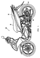
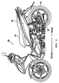
- FIG. 1 is an external side view schematically showing a construction of the straddle type vehicle 100 of this embodiment.
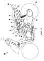
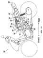
- FIG. 2 is a side view illustrating a construction around a battery housing part 10 according to this embodiment.
- the straddle type vehicle 100 is a motorcycle of a so-called underbone frame type.
- the vehicle 100 is a vehicle having a helmet and a battery disposed under a seat, and is constructed with a seat 30 on which a rider is to be seated, a helmet housing box 20 disposed under the seat, and a battery housing part 10 disposed in front of the helmet housing box 20 in the vehicle fore-and-aft direction.
- the seat 30 of this embodiment is disposed in a vicinity of a center of the vehicle in a manner such that a direction of the length thereof is along the vehicle fore-and-aft direction.
- a rear part of the seat 30 is formed to extend to a rear end of the vehicle 100.
- a pair of body covers 68 is provided obliquely below right and left sides of the seat 30.
- a space having an opening covered by the seat 30 is provided inside the body covers 68.
- a front end of the seat 30 of this embodiment is mounted on the vehicle body so as to be rotatable via a hinge 32. The space having an opening formed under the seat can be exposed by opening the seat 30 upward in this construction.
- the helmet housing box 20 is provided in the space having an opening under the seat.
- the helmet housing box 20 of this embodiment is disposed in the front of the space having an opening under the seat, and positioned forwardly below a fuel tank 67 provided adjacently in the rear.
- the helmet housing box 20 is a container for housing a helmet (not shown), and can house all sorts of articles instead of a helmet.
- An upper region of the helmet housing box 20 defines an opening 22 for inserting and removing the helmet and so forth.
- the opening 22 is selectively closed by an inner lid 23.
- the battery housing part 10 for housing a battery 12 is disposed in front of the helmet housing box 20 in the vehicle fore-and-aft direction.
- the battery housing part 10 of this embodiment is a resin member formed integrally with the helmet housing box 20.
- a front part of the battery housing part 10 is disposed to extend to a vicinity of the front end of the seat 30.
- the battery housing part 10 and the helmet housing box 20 may be produced as parts separated from each other.
- a lid 24 serving as a part of an inner wall 26 of the helmet housing box 20 is disposed at a boundary between the battery housing part 10 and the helmet housing box 20. The lid 24 separates a space for the battery housing part from a space for the helmet housing box.
- An engine 40 and a fuel spray device 44 for supplying fuel to the engine 40 are disposed below the seat 30.
- the engine 40 of this embodiment is disposed below a boundary between the helmet housing box 20 and the battery housing part 10.
- the engine 40 is disposed in front of the helmet housing box 20 in the vehicle fore-and-aft direction and in a position below the helmet housing box 20.
- Driving force of the engine 40 is transmitted to a rear wheel 65 via a drive transmission system in a transmission casing 66, and drives the rear wheel 65.
- the engine 40 of this embodiment is a swing type engine. That is, a unit in which the engine 40 and the transmission casing 66 are integrated (a drive unit) is coupled to a vehicle body frame 60 swingably in a vertical direction via a pivot shaft in a vicinity of the engine 40.
- a rear end of the transmission casing 66 is connected to a rear part of the vehicle body frame 60 via a rear cushion unit 69.
- impacts that can occur, for example, in the case of traveling on a rough road can be absorbed by swing movements of the drive unit, and thereby oscillations of the vehicle can be reduced.
- the fuel spray device 44 is a member for supplying fuel to the engine 40, which is a carburetor, for example.
- the fuel spray device 44 of this embodiment is disposed below the front end of the seat 30 and obliquely forwardly above the engine 40.
- the fuel spray device 44 constructs a part of the drive unit described above, and swings in the vertical direction following swing movements of the drive unit.
- the battery housing part 10 is disposed in a space between the fuel spray device 44, which swings in the vertical direction, and the seat 30. That is, in a side view, the battery 12 in the battery housing part 10 is positioned above the engine 40 and the fuel spray device 44.
- the space between the fuel spray device 44 and the seat 30 is conventionally an unused space in which parts cannot be disposed since the fuel spray device 44 swings in the vertical direction. This is because if a part was disposed in the space, the part would have to be disposed in an upper part of the space to prevent it from swinging in the vertical direction, which would result in a large seat height and make it difficult for the rider to put his/her feet on the ground.
- the unused space above the fuel spray device 44 can be utilized as a battery housing space by means of arranging a construction of the vehicle. Therefore, a space which is conventionally a battery housing space can be effectively utilized as a space for other parts.
- the battery housing part 10 is positioned in front of the helmet housing box 20 and above the engine 40 and the fuel spray device 44. Therefore, the battery 12 having a relatively large weight and the engine 40 also having a large weight are concentrated in a generally common region in the vehicle fore-and-aft direction. Thus, it is attempted that heavy loads are concentrated generally in a middle part in the vehicle fore-and-aft direction. As a result, driving characteristics and operability of the vehicle can be improved. In scooter type vehicles, in particular, a load on the rear wheel tends to be large, and, therefore, a large advantage can be obtained by disposing a heavy battery in the vicinity of the center of the vehicle and concentrating a mass.
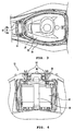
- FIG. 3 is a top view of essential parts around the battery housing part on a larger scale.
- FIG. 4 is an external view of the battery housing part as seen in a direction of an arrow "IV" in FIG. 2 . In FIG. 4 , a part of the lid 24 is cut away so that an inside of the battery housing part can be seen.
- the lid 24 of this embodiment is disposed at the boundary between the helmet housing box 20 and the battery housing part 10, and separates the helmet housing box 20 from the battery housing part 10.
- the lid 24 of this embodiment is bolted to the helmet housing box 20 removably with use of a tool. That is, as shown in FIG. 4 , the lid 24 is fixed to mounting parts 57 provided in upper parts of the inner wall of the helmet housing box via two screws 56. Therefore, the lid 24 can be removed by loosening the two screws 56 with use of a tool (such as a screwdriver).
- the battery 12 housed in the battery housing part 10 can be exposed to a large extent in a state that the lid 24 is removed as described above.
- the battery 12 can be easily checked and/or replaced from the inside of the helmet housing box 20 by opening the seat 30 upward and then removing the lid 24 with use of a tool. This improves ease in maintenance of the battery 12.
- a vertically extending band-shaped belt 58 is mounted at the boundary between the helmet housing box 20 and the battery housing part 10 in addition to the lid 24. That is, the maintenance of the battery 12 and so forth described above can be made by removing the lid 24 and further removing the belt 58 thereafter.
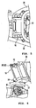
- FIG. 5 is an enlarged view of essential parts showing a vicinity of the battery housing part as seen from above.
- FIG. 6 is an enlarged view of essential parts showing the vicinity of the battery housing part as seen from a side.
- FIG. 7 is an exploded perspective view of the battery housing part 10 and the helmet housing box 20. In FIG. 5 , members are partially cut away for understanding of a state of a lower part of the battery housing part 10.
- the battery housing part 10 is disposed in a space in front of the helmet housing box 20 and between right and left seat rail frames 35.
- the fuel spray device 44 is disposed below the battery housing part 10.
- the battery housing part 10 is disposed to incline forward in a manner such that an upper part thereof is positioned in front of a lower part. Therefore, the battery 12 in the battery housing part 10 is supported in the forwardly inclining position, and exposed obliquely upward in the case that the lid 24 is removed.
- the battery housing part 10 is made compact in the vertical direction. As a result, the height of the seat is lowered and operational stability can be improved.
- the hinge 32 for rotatably supporting the seat 30 is provided in the upper part of the battery housing part 10.
- the hinge 32 is constructed with a supporting shaft 34 and a pair of mounting pieces 33a and 33b in which the supporting shaft 34 is fitted.
- the seat 30 is fixed to the hinge 32 via bolts and nuts.
- the battery housing part 10 can bear a load acting on the hinge 32 when the seat is opened by providing the hinge 32 formed integrally with the battery housing part 10 in the upper part of the battery housing part 10 in the above manner. Thereby, sufficient mounting strength for the seat 30 can be obtained.
- the hinge is disposed in the upper part of the battery housing part, and thus the battery housing part can bear the weight of a rider. Therefore, it is not required to provide a rib separately, and a number of vehicle parts can be reduced. It is required only that the battery housing part be in a shape having strength sufficient to bear the weight of a rider.
- a box type battery housing part can preferably be used as a typical example.
- a compact arrangement can be achieved by providing the hinge 32 in the upper part of the battery housing part 10, comparing with a case that the hinge is disposed in a front part of the battery housing part 10.
- a support 14 is disposed at a bottom of the battery housing part 10. Specifically, a bottom hole 15 is formed, vertically passing through a lower surface of the battery housing part 10 made of resin material.
- the support 14 in the shape of a board serving as the bottom surface of the battery housing part 10 is detachably attached to the bottom hole 15.
- the support 14 is fixed to an outer wall of the battery housing part 10 via bolts 17, and blocks the bottom hole 15 from a lower side thereof. With such a construction, the battery 12 housed in the battery housing part 10 is supported by an upper surface of the support 14.
- a material for the support 14 is not limited to a particular material as long as it has strength sufficient for supporting the battery 12.
- the support 14 made of a metal material (such as sheet metal part) may be preferably used.
- the battery housing part 10 bears the load of the seat 30 when the seat is opened as described above.
- the support 14 made of metal having strength higher than resin can be utilized as a strength member.
- Two types of support 14 are constructed such that an elevation of the battery 12 is adjustable.
- the support 14 can be replaced by removing the bolts 17.
- a housing volume of the battery housing part 10 can be properly adjusted by replacing the support 14 with a different shape.
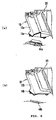
- a support 14a in FIG. 8 (a) has such a shape that only a part of an upper surface thereof on which the battery 12 is set for a support partially protrudes above a bottom surface of the battery housing part 10.
- a part corresponding to a carburetor 44a of a lower surface of the support 14a is partially recessed.
- the support 14b has such a shape that an upper surface thereof is generally flush with the bottom surface of the battery housing part 10.
- the support 14a is constructed to lift up a bottom surface of the battery 12 from the bottom of the battery housing part 10
- the support 14b is constructed such that the bottom of the battery 12 is disposed close to the bottom of the battery housing part 10 to increase the housing volume of the battery housing part 10. Therefore, a housing volume of the battery housing part 10 can be increased by replacing the support 14a with the support 14b. This enables an installation of a large battery.
- the support 14 is replaceable as described above, the preferable support 14 may be appropriately selected according to a size of an installed battery. Accordingly, it is not required to change vehicle arrangements for different battery sizes for vehicles of the same exterior but of different specifications.
- the housing volume of the battery housing part 10 is variable by replacement of the support 14 with the upper surface having a different height.
- the support 14 can properly adjust an elevation of the bottom of the battery housing part 10.
- the support 14 itself may be provided with a function for adjusting the height of the bottom of the battery housing part 10. In this case, trouble with replacement between the supports 14 can be saved.
- the battery housing part 10 of this embodiment is disposed above the fuel spray device 44 as described above. Therefore, the support 14 in the preferable shape may be appropriately selected according to a size and so forth of the fuel spray device 44 to be installed. For example, in the case that a carburetor is used as the fuel spray device 44, a volume of the whole system becomes relatively large compared to a fuel injector (FI), while a battery capacity (battery size) becomes relatively small compared to an FI. Therefore, the support 14a having the lower surface partially recessed in an area corresponding to the carburetor 44a as shown in FIG. 8(a) is used to house a relatively small battery 12a in the case that the carburetor 44a is installed. Thereby, a large space for mounting the carburetor 44a can be provided by enlarging a space formed below the battery housing part 10.
- the support 14b having the upper surface generally flush with the bottom of the battery housing part 10 is used as shown in FIG. 8(b) in the case that a fuel injector (FI) 44b is installed as the fuel spray device 44.
- a fuel injector (FI) 44b is installed as the fuel spray device 44.
- FIG. 9 is an external side view schematically illustrating a construction of the straddle type vehicle 200 according to the embodiment.
- FIG. 10 is a schematic side view illustrating a construction under a seat of the vehicle 200.
- the straddle type vehicle 200 is a so-called underbone type motorcycle.
- the vehicle 200 is a vehicle capable of housing a helmet under a seat, and is constructed with a seat 130 on which a rider is to be seated, a helmet housing box 120 disposed under the seat, a battery housing part 140 disposed in front of the helmet housing box 120 in the vehicle direction, and an electrical equipment container 110 disposed below the helmet housing box 120.
- the seat 130 of this embodiment is disposed in a vicinity of a center of the vehicle in a manner such that a direction of the length thereof is along the vehicle fore-and-aft direction.
- a rear part of the seat 130 is formed to extend to a rear end of the vehicle 200.
- a pair of body covers 168 is provided obliquely below right and left sides of the seat 130.
- a space having an opening covered by the seat 130 is provided inside the body covers 168.
- a front end of the seat 130 of this embodiment is mounted on the vehicle body so as to be rotatable via a hinge 132. The space having an opening formed under the seat can be exposed by opening the seat 130 upward.
- the helmet housing box 120 is provided in the space having an opening under the seat.
- the helmet housing box 120 of this embodiment is disposed in the front of the space having an opening under the seat, and positioned forwardly below a fuel tank 167 provided adjacently in the rear.
- the helmet housing box 120 is a container for housing a helmet (not shown), and can house all sorts of articles instead of a helmet.
- the opening 22 for inserting and removing a helmet and so forth is provided above the helmet housing box 120.
- the opening 22 is selectively covered with a lid 123.
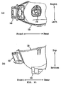
- FIG. 11 is enlarged views of essential parts around the helmet housing box 120.
- FIG. 11 (a) shows an upper surface thereof, while FIG. 11(b) shows a side thereof.
- the battery housing part 140 for housing a battery 142 is disposed on the side of the helmet housing box 120.
- the battery housing part 140 of this embodiment is a resin member formed integrally with the helmet housing box 120, and is provided in front of the helmet housing box 120.
- the battery housing part 140 and the helmet housing box 120 may be produced as parts separated from each other.
- An inner lid 146 (a first inner lid 146) is disposed at a boundary between the battery housing part 140 and the helmet housing box 120. The inner lid 146 separates a space for the battery housing part from a space for the helmet housing box.
- the electrical equipment container 110 is disposed on a bottom surface of the helmet housing box 120.
- the electrical equipment container 110 of the embodiment is a member made of resin formed integrally with the helmet housing box 120, and provided generally in a middle part of the bottom surface of the helmet housing box 120.
- An upper part of the electrical equipment container 110 is an open end, and the electrical equipment container 110 is connected to the inside of the helmet housing box 120 via the open end.
- an inner lid 116 (a second inner lid 116) is disposed at a boundary between the electrical equipment container 110 and the helmet housing box 120.
- a housing space of the electrical equipment container 110 is separated from a housing space of the helmet housing box 120 by the inner lid 116.
- Electrical equipment 112 is housed in the electrical equipment container 110.
- the electrical equipment 112 is, for example, a starter relay and a fuse.
- the electrical equipment 112 is electrical equipment mounted on a typical straddle type vehicle and is not particularly limited. In the embodiment, a fuse integrated with a starter relay is mounted.
- a starter relay 112a is interposed between a starter motor (not shown) and the battery 142, and has a function as a substantial switch operating the starter motor by receiving an input from a starter switch on a handlebar.
- the starter relay 112a is electrically connected to the battery 142 via wiring 152 and electrically connected to the starter motor via wiring 154.
- the starter motor of the embodiment is provided on an engine 162 (see FIG. 10 ) in the same manner as a starter motor mounted on a typical straddle type vehicle, and is a typical example of an "external member" disposed outside the electrical equipment container 110 (the helmet housing box 120).
- a coupler is interposed in a middle of the wiring 154 connecting the starter motor (external member). Specifically, a first coupler 170a connected to the end of wiring 154a extended from the starter relay 112a and a second coupler (not shown) connected to the end of wiring (not shown) extended from the starter motor (external member) are provided. The starter relay 112a and the starter motor (external member) are electrically connected by fitting the first coupler 170a and the second coupler.
- the first coupler 170a is fixed on a coupler retainer 172 formed integrally with the bottom surface of the electrical equipment container 110. In this embodiment, the coupler retainer 172 is provided on a right side of the bottom surface of the electrical equipment container 110, and coupler retainer 172 fixes the first coupler 170a not to move.
- wiring between the starter relay 112a (electrical equipment) in the electrical equipment container 110 connected to the helmet housing box 120 and the starter motor (external member) disposed outside the helmet housing box 120 is arranged by connecting the first coupler 170a connected to the end of the wiring 154a extended from the starter relay 112a (electrical equipment) and the second coupler connected to the end of the wiring extended from the starter motor (external member). Accordingly, the electrical equipment 112 (starter relay 112a) and the external member (starter motor) can be connected after the helmet housing box 120 is assembled with the vehicle body. Thereby, assembly performance thereof is improved.
- the first coupler 170a connected to the end of the wiring 154a extended from the starter relay 112a (electrical equipment) is fixed on the coupler retainer 172 formed integrally with the electrical equipment container 110. Consequently, it is possible to firmly fix the first coupler 170a. Therefore, it can be avoided that the coupler comes off due to vibrations or the like while the vehicle is running.
- the battery housing part 140 is disposed on the side of the helmet housing box 120, and the electrical equipment container 110 is disposed on the bottom surface of the helmet container 120. Consequently, it is possible to dispose the battery 142 and the electrical equipment 112 (starter relay 112a) relatively in a vicinity of each other. Because of this, it can be prevented that voltage between the battery 142 and the electrical equipment 112 is reduced.
- the electrical equipment container 110 is disposed on the bottom surface of the helmet housing box 120. Therefore, distance between the starter relay 112a (electrical equipment) and the engine 162 (starter motor in particular) is also reduced (see FIG. 9 ). Thereby, it is possible to simplify wiring 54 connecting the starter relay 112a and the engine 162.
- a drawing opening for drawing in the second coupler from the starter motor (external member) is opened in a side surface on the front side of the electrical equipment container 110. Consequently, it is possible to draw in the second coupler in the electrical equipment container 110 via the drawing opening.
- the drawing opening is provided in a vicinity of the coupler retainer 172, work for connecting wire between the first coupler 170a and the second coupler becomes easy.
- wiring 152 for the battery is drawn out of the electrical equipment container 110 (helmet housing box 120) from the drawing opening described above, and is connected to the battery 142 via an opening on the side of the battery housing part. As the wiring 152 for the battery is drown out of the helmet housing box 120, it is possible to make an interior of the helmet container free from wiring etc. Since high voltage is applied to the wiring 152 for the battery, it is preferable that a coupler is not interposed in the middle of the wire connected between the battery 142 and the electrical equipment 112.
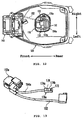
- FIG. 13 is a perspective view of an external appearance of the electrical equipment 112a provided with the first coupler 170a.
- the wiring 152 to be connected to the battery 142 and the wiring 154a on the side of the starter relay of the wiring 154 to be connected to the starter motor are extended from the starter relay 112a as a part of the electrical equipment 112.
- the first coupler 170a is attached on the end of the wiring 154a.
- the first coupler 170a of the embodiment is a so-called female coupler with an open end with which the top of a second coupler can be fitted.
- the first coupler 170a comprises a casing generally in the shape of a cuboid, and is constructed with a case middle part 174 constructing a main body thereof and a protruding portion 173 formed on an upper surface of the case middle part 174.
- an inclined step 179 is formed on an upper surface of the case middle part 174 in addition to the protruding portion 173.
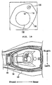
- FIG. 14 (a) is a top view of the coupler retainer 172
- FIG. 14 (b) is a perspective view of an external appearance of the coupler retainer 172.
- the coupler retainer 172 is provided with a latch member 175 for latching the case middle part 174 of the first coupler 170a by surrounding the case middle part 174.
- the latch member 175 of this embodiment is constructed with a pair of projecting portions 177a and 177b and a clasp 178.
- the projecting portions 177a and 177b are a pair of members projecting upward from an upper surface of the electrical equipment container 110.
- the projecting portions 177a and 177b of this embodiment are disposed apart from each other, so that the case middle part 174 can pass between the projecting portions 177a and 177b.
- upper parts of the projecting portions 177a and 177b bend internally (in directions in which they face each other), and a guide groove 176 having a narrow width is formed.
- the guide groove 176 has a groove width narrow enough for the projection 173 of the first coupler 170a to pass through the guide groove 176.
- inclined steps 171a and 171b are formed on a lower surface of bending portions of the projecting portions 177a and 177b respectively.
- the clasp 178 is provided on the upper surface of the electrical equipment container 110, and is disposed rearwardly of the projecting portions 177a and 177b.
- the clasp 178 of this embodiment is a projection in a linear shape made of a resin material, and is formed so that the length direction thereof is along the traverse direction of the vehicle.
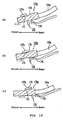
- FIGs. 15(a) to 15(c) are external perspective views illustrating the procedure for fixing the first coupler 170a on the coupler retainer 172
- FIGs. 16(a) to 16(c) are schematic views thereof. Firstly, the protruding portion 173 of the first coupler 170a is fitted in the guide groove 176 as illustrated in FIG. 15(a) and FIG. 16(a) .
- the case middle part 174 of the first coupler 170a is fitted in the lower side of the bending portion of a pair of the projecting portions 177a and 177b, and the case middle part 174 is slid frontward.
- a position of the first coupler 170a in the traverse direction of the vehicle is fixed by passing the first coupler 170a between a pair of the projecting portions 177a and 177b.
- the case middle part 174 is slid further frontward, and the step 179 of the first coupler 170a and the steps 171a and 171b of the projecting portions are made to come in contact. As they come in contact in this manner, a forward movement of the first coupler 170a is restricted.
- the clasp 178 comes to a rear surface of the case middle part 174. The clasp 178 restricts a rearward movement of the first coupler 170a. In this manner, the position of the first coupler 170a in the vehicle fore-and-aft direction is fixed.
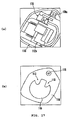
- the inner lid 116 (second inner lid 116) is disposed at a boundary between the electrical equipment container 110 and the helmet housing box 120.
- the inner lid 116 of this embodiment is detachably fixed by a screw on the helmet housing box 120 via a screw 115 as a fastening member. Because of this, it is possible to hide the electrical equipment with the inner lid 116 at a usual time. Thereby, it is possible to improve the appearance of an interior of the helmet housing box.
- a cushion member 118 for a helmet is provided on a surface on a side of the helmet housing box of the second inner lid 116.
- the cushion member 118 of this embodiment is made of a sponge generally in the shape of a disk, and is disposed generally in a middle part of the inner lid 116.
- a cutout 113 is formed in a part of the cushion member 118. It is possible to hold the inner lid 116 via the cutout 113 in this construction.
- the inner lid may not necessarily be held by the cutout described above but may be held by some other means.
- a protruding portion 114 may be provided on the cushion member 118, so that the protruding portion 114 can be held in this construction.
- the inner lid 146 (first inner lid) is disposed at the boundary between the helmet housing box 120 and the battery housing part 140 to separate the helmet housing box 120 from the battery housing part 140.
- the inner lid 146 of this embodiment is removably fixed on the helmet housing box 120 by screws with use of a tool.
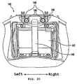
- the inner lid 146 as illustrated in FIG. 20 , is fastened and fixed on a mount section 149 provided on an upper side of the inner wall of the helmet housing part via two screws 148 (fastening members). Accordingly, it is possible to remove the inner lid 146 by releasing the connection of the two screws 148 by using a tool (a screwdriver for example).
- the battery 142 housed in the battery housing part 140 can be exposed to a large extent in a state that the inner lid 146 is removed as described above.
- the battery 142 can be easily checked and/or replaced from the inside of the helmet housing box 120 by opening the seat 130 upward and next removing the inner lid 146 with use of a tool. This improves facility in maintenance of the battery 142.
- a band-shaped belt 145 extending vertically is mounted at the boundary between the helmet housing box 120 and the battery housing part 140 in addition to the lid 123. That is, the maintenance of the battery 142 and so forth described above can be made by removing the inner lid 146 and further removing the belt 145 thereafter in this construction.
- the "straddle type vehicle” in this specification is not limited to vehicles in which a rider is seated while straddling a seat, but also includes vehicles in which a rider is seated with both his/her legs placed next to each other (typically scooter type vehicles).
- the straddle type vehicle 100 shown in FIG. 1 and the straddle type vehicle 200 shown in FIG. 9 are underbone type motorcycles.
- the present invention is not limited to this case, but is applicable to a straddle type vehicle having a battery housing part under a seat.
- the present invention is applicable to vehicles other than underbone type motorcycles such as four-wheeled buggies (ATV: All Terrain Vehicle) and snowmobiles.
- ATV All Terrain Vehicle
- the present invention can provide a straddle type vehicle having a battery disposition by which heavy loads are concentrated and thereby operability of the vehicle is improved.
Landscapes
- Engineering & Computer Science (AREA)
- Mechanical Engineering (AREA)
- Aviation & Aerospace Engineering (AREA)
- Chemical & Material Sciences (AREA)
- Chemical Kinetics & Catalysis (AREA)
- Electrochemistry (AREA)
- General Chemical & Material Sciences (AREA)
- Automatic Cycles, And Cycles In General (AREA)
Description
- The present invention relates to a straddle type vehicle, in particular, a straddle type vehicle including a battery housing part under a seat.
- Some straddle type vehicles have a housing box (a so-called helmet housing box) disposed for housing articles (for example, a helmet) beneath a seat. Further, there are many vehicles having vehicle equipment such as a fuel tank and a battery disposed adjacent to the housing box. For example,
JP-A-2002-225765 - In the technique in
JP-A-2002-225765 -
EP 1 275 830 describes a scooter having an engine unit pivoted for vertical swing mounted behind a footrest. A carburettor is connected to an air outlet formed on the top surface of an air cleaner. The area below a seat is surrounded with part of a vehicle cover and a side cover. An article box is formed in the side cover. A bottom portion of the article holding box is sink-formed to be a battery holding portion in which a battery is held. -
EP 1 108 644 describes a two-wheeled vehicle having a battery in front of a luggage box 61 and the luggage box and battery being covered by a lower seat cover. The engine of the vehicle is located beneath and towards the rear of the luggage box. -
EP 1 772 360 andJP3-258677 - The present invention is made in consideration of such a problem, and has a main object to provide a straddle type vehicle having a heavy load disposition by which heavy loads are concentrated to improve operability of the vehicle.
- Various aspects of the present invention are defined in the independent claim 1. Some preferred features are defined in the dependent claims 2 - 15.
- Described herein is a straddle type vehicle having a helmet and a battery disposed under a seat, including: a helmet housing box having an opening at a top surface thereof for putting in and out a helmet; an engine disposed in front of the helmet housing box in the vehicle direction and below the helmet housing box; a fuel spray device disposed above the engine; and a battery housing part disposed in front of the helmet housing box in the vehicle direction and in a position above the fuel spray device, in which the battery is housed in the battery housing part.
- The battery housing part may have a bottom hole passing through a bottom surface of the battery housing part. A support for supporting the battery may be detachably attached to the bottom hole.
- The support may have such a shape that only a part supporting the battery partially protrudes above the bottom of the battery housing part.
- The fuel spray device may be a carburetor, and the support may be in the shape of a board and may be in such a mode that a part supporting the battery on a bottom surface thereof is recessed corresponding to the carburetor.
- The fuel spray device may be a fuel injection system, and the support may be formed such that an upper surface thereof is generally flush with the bottom of the battery housing part.
- A plurality of types of the support of different height supporting the battery in the battery housing part may be selectively attached to the bottom of the battery housing part.
- The support may comprise a metal member.
- A lid serving as a part of an inner wall of the helmet housing box may be provided at a boundary between the battery housing part and the helmet housing box.
- Electrical equipment disposed around the helmet housing box and connected to the battery by a wire, a first coupler connected to the end of wiring extended from the electrical equipment, and a coupler retainer for fixing the first coupler are provided, in which the battery housing part is connected to the helmet housing box, the electrical equipment is housed in an electrical equipment housing part connected to the helmet housing box, and the first coupler fixed by the coupler retainer is connected to a second coupler connected to the end of wiring extended from an external member.
- The electrical equipment may include a starter relay, and the external member may comprise a starter motor provided to an engine of the straddle type vehicle.
- A clasp for hooking a rear part of a case of the first coupler may be formed on the coupler retainer.
- A latch member for latching a middle part of a case of the first coupler by surrounding the middle part may be provided on the coupler retainer, a protruding portion may be formed on the case of the first coupler, and a groove for guiding the first coupler by fitting the protruding portion formed on the first coupler may be formed on the latch member.
- A first inner lid may be provided between the helmet housing box and the battery housing part, and a second inner lid may be provided between the helmet housing box and the electrical equipment housing part.
- The first inner lid and the second inner lid may be fixed on the helmet housing box respectively by a fastening member.
- The battery housing part may be disposed on a side of the helmet housing box, the electrical equipment housing part may be disposed on the bottom of the helmet housing box, and a cushion member for the helmet may be provided on a surface on a side of the helmet housing part of the second inner lid.
- Described herein is a straddle type vehicle comprising:
- a seat;
- a helmet housing box disposed below the seat and having an opening at a top surface thereof for permitting insertion and removal of a helmet;
- an engine disposed in front of and below the helmet housing box;
- a fuel spray device disposed above the engine; and
- a battery housing part disposed in front of the helmet housing box and in a position above the fuel spray device.
- The battery housing part may define a bottom hole passing through a bottom surface thereof. A support for supporting the battery may be detachably attached to at least partially cover the bottom hole.
- The support may be configured such that only a part for supporting a battery partially protrudes above the bottom of the battery housing part.
- The fuel spray device may comprise a carburetor. The fuel spray device may comprise a fuel injection system. The support may be configured in the shape of a board and a part for supporting a battery on a bottom surface thereof may be recessed relative to the fuel spray device, such as a carburetor. The support may be configured such that an upper surface thereof is generally flush with the bottom of the battery housing part.
- The support may be selected from a plurality of supports adapted to support a battery at different heights within the battery housing part.
- A hinge for rotatably supporting the seat may be formed at an upper part of the battery housing part.
- A lid serving as a part of an inner wall of the helmet housing box may be provided at a boundary between the battery housing part and the helmet housing box.
- The vehicle may further comprise electrical equipment disposed around the helmet housing box and connected to a battery disposed within the battery housing part by a wire. A first coupler may be connected to the end of wiring extended from the electrical equipment. A coupler retainer may be provided for fixing the first coupler. The battery housing part may be connected to the helmet housing box. The electrical equipment may be housed in an electrical equipment housing part connected to the helmet housing box. The first coupler fixed to the coupler retainer may be connected to a second coupler connected to the end of wiring extended from an external member.
- The electrical equipment may comprise a starter relay. The external member may comprise a starter motor coupled to an engine of the straddle type vehicle.
- A clasp for hooking a rear part of a case of the first coupler may be formed on the coupler retainer.
- A latch member for latching a middle part of a case of the first coupler by surrounding the middle part may be provided on the coupler retainer. A protruding portion may be formed on the case of the first coupler retainer. A groove for guiding the first coupler by fitting the protruding portion formed on the first coupler may be formed on the latch member.
- A first inner lid may be provided between the helmet housing box and the battery housing part, and a second inner lid may be provided between the helmet housing box and the electrical equipment housing part.
- The first inner lid and the second inner lid may be fixed on the helmet housing box respectively by a fastening member.
- The battery housing part may be disposed on a side of the helmet housing box. The electrical equipment housing part may be disposed on the bottom of the helmet housing box. A cushion member adapted to be engaged by a helmet received within the helmet housing box may be provided on a surface on a side of the helmet housing box of the second inner lid.
- The support may comprise a metal member. The support may alternatively, or additionally, comprise a plastic material, composite material or the like.
- In a straddle type vehicle according to the present invention, the battery housing part is disposed in front of the helmet housing box in the vehicle direction and in a position above the engine and the fuel spray device. Accordingly, the battery having a relatively large weight and the engine also having a large weight are concentrated in the vehicle fore-and-aft direction. Because of this, it can be avoided that heavy loads are distributed in the vehicle fore-and-aft direction. Consequently, driving characteristics and operability of the vehicle can be improved. In addition, a space between the fuel spray device and the seat can be utilized as a battery housing space. Therefore, a space which is conventionally a battery housing space can be effectively utilized as a space for other parts.
- The vehicle includes the lid serving as a part of the inner wall of the helmet housing box at the boundary between the battery housing part and the helmet housing box. Thus, a battery can be checked and/or replaced easily from an inside of the helmet housing box by opening the seat and removing the lid. This improves facility in battery maintenance.
- Further, the electrical equipment housed in the electrical equipment housing part connected to the helmet housing box and the external member disposed outside the helmet housing box and connected to the electrical equipment by a wire are provided. In addition, the wire between the electrical equipment and the external member is connected by connecting the first coupler connected to the end of wiring extended from the electrical equipment and the second coupler connected to the end of wiring extended from the external member.
- As the couplers are interposed in a middle of the wiring connecting the electrical equipment and the external member, it becomes easy to assemble the electrical equipment and the external member. In other words, it is possible to connect the electrical equipment and the external member by the wire even after the helmet housing box is assembled with the vehicle body. Accordingly, assembly performance thereof is improved. In addition, as the first coupler connected to the end of the wiring extended from the electrical equipment is fixed on the coupler retainer formed integrally with the electrical equipment container. Accordingly, it is possible to firmly fix the first coupler. Therefore, it can be avoided that the coupler comes off due to vibrations or the like while a vehicle is running.
- These and other aspects of the present invention will now be described, by way of example only, with reference to the accompanying drawings, in which:
-
FIG. 1 is an external side view schematically showing a construction of astraddle type vehicle 100 according to a first embodiment; -
FIG. 2 is a side view illustrating a construction around abattery housing part 10 according to the first embodiment; -
FIG. 3 is a top view of essential parts around the battery housing part on a larger scale; -
FIG. 4 is an external view of the battery housing part as seen in a direction of an arrow "IV" inFIG. 2 ; -
FIG. 5 is an enlarged view of essential parts showing a vicinity of the battery housing part as seen from above; -
FIG. 6 is an enlarged view of essential parts showing the vicinity of the battery housing part as seen from a side; -
FIG. 7 is an exploded perspective view of the battery housing part and a helmet housing box; -
FIG. 8 (a) is a schematic side view in a case that a fuel spray device is a carburetor; -
FIG. 8(b) is a schematic side view in a case that the fuel spray device is a fuel injector; -
FIG. 9 is an external side view schematically showing a construction of a straddle type vehicle according to a second embodiment; -
FIG. 10 is a schematic side view illustrating a construction under a seat of the vehicle; -
FIG. 11(a) illustrates an upper surface of a housing box of the vehicle of the second embodiment; -
FIG. 11 (b) illustrates a side thereof of a housing box of the vehicle of the second embodiment; -
FIG. 12 is a drawing illustrating a construction of an inside of electrical equipment container; -
FIG. 13 is an external perspective view of electrical equipment and wiring; -
FIG. 14(a) is a top view of a coupler retainer; -
FIG. 14 (b) is an external perspective view of the coupler retainer; -
FIGs. 15(a) to 15(c) are drawings illustrating a procedure for fixing a first coupler on a coupler retainer; -
FIGs. 16(a) to 16(c) are drawings illustrating a procedure for fixing the first coupler on the coupler retainer; -
FIG. 17(a) is an enlarged view of essential parts of an electrical equipment housing part at a time when an inner lid is removed; -
FIG. 17(b) is an enlarged view of essential parts of the electrical equipment housing part at a time when the inner lid is attached; -
FIG. 18 is a drawing illustrating an example of modification of this embodiment; -
FIG. 19 is an enlarged view of essential parts around a battery housing part at a time when an inner lid is attached; and -
FIG. 20 is an external view of the battery housing part as seen from a direction of a helmet housing box. - A first embodiment according to the present invention will be described hereinafter with reference to accompanying drawings. In the accompanying drawings, members and parts effecting the same operation are referred to with the same reference numerals and symbols. The present invention is not limited to the embodiment below.
- A
straddle type vehicle 100 in the embodiment according to the present invention (also simply referred to as a "vehicle") will be described with reference toFIGs. 1 and2 .FIG. 1 is an external side view schematically showing a construction of thestraddle type vehicle 100 of this embodiment.FIG. 2 is a side view illustrating a construction around abattery housing part 10 according to this embodiment. - The
straddle type vehicle 100 according to the embodiment is a motorcycle of a so-called underbone frame type. Thevehicle 100 is a vehicle having a helmet and a battery disposed under a seat, and is constructed with aseat 30 on which a rider is to be seated, ahelmet housing box 20 disposed under the seat, and abattery housing part 10 disposed in front of thehelmet housing box 20 in the vehicle fore-and-aft direction. - The
seat 30 of this embodiment is disposed in a vicinity of a center of the vehicle in a manner such that a direction of the length thereof is along the vehicle fore-and-aft direction. A rear part of theseat 30 is formed to extend to a rear end of thevehicle 100. A pair of body covers 68 is provided obliquely below right and left sides of theseat 30. A space having an opening covered by theseat 30 is provided inside the body covers 68. A front end of theseat 30 of this embodiment is mounted on the vehicle body so as to be rotatable via ahinge 32. The space having an opening formed under the seat can be exposed by opening theseat 30 upward in this construction. - The
helmet housing box 20 is provided in the space having an opening under the seat. Thehelmet housing box 20 of this embodiment is disposed in the front of the space having an opening under the seat, and positioned forwardly below afuel tank 67 provided adjacently in the rear. Thehelmet housing box 20 is a container for housing a helmet (not shown), and can house all sorts of articles instead of a helmet. An upper region of thehelmet housing box 20 defines anopening 22 for inserting and removing the helmet and so forth. Theopening 22 is selectively closed by aninner lid 23. - The
battery housing part 10 for housing abattery 12 is disposed in front of thehelmet housing box 20 in the vehicle fore-and-aft direction. Thebattery housing part 10 of this embodiment is a resin member formed integrally with thehelmet housing box 20. A front part of thebattery housing part 10 is disposed to extend to a vicinity of the front end of theseat 30. Thebattery housing part 10 and thehelmet housing box 20 may be produced as parts separated from each other. Alid 24 serving as a part of aninner wall 26 of thehelmet housing box 20 is disposed at a boundary between thebattery housing part 10 and thehelmet housing box 20. Thelid 24 separates a space for the battery housing part from a space for the helmet housing box. - The arrangement of the
battery housing part 10 will now be described in further detail. Anengine 40 and afuel spray device 44 for supplying fuel to theengine 40 are disposed below theseat 30. - The
engine 40 of this embodiment is disposed below a boundary between thehelmet housing box 20 and thebattery housing part 10. In other words, theengine 40 is disposed in front of thehelmet housing box 20 in the vehicle fore-and-aft direction and in a position below thehelmet housing box 20. Driving force of theengine 40 is transmitted to arear wheel 65 via a drive transmission system in a transmission casing 66, and drives therear wheel 65. Theengine 40 of this embodiment is a swing type engine. That is, a unit in which theengine 40 and the transmission casing 66 are integrated (a drive unit) is coupled to a vehicle body frame 60 swingably in a vertical direction via a pivot shaft in a vicinity of theengine 40. A rear end of the transmission casing 66 is connected to a rear part of the vehicle body frame 60 via arear cushion unit 69. In such a construction, impacts that can occur, for example, in the case of traveling on a rough road can be absorbed by swing movements of the drive unit, and thereby oscillations of the vehicle can be reduced. - The
fuel spray device 44 is a member for supplying fuel to theengine 40, which is a carburetor, for example. Thefuel spray device 44 of this embodiment is disposed below the front end of theseat 30 and obliquely forwardly above theengine 40. Thefuel spray device 44 constructs a part of the drive unit described above, and swings in the vertical direction following swing movements of the drive unit. - The
battery housing part 10 is disposed in a space between thefuel spray device 44, which swings in the vertical direction, and theseat 30. That is, in a side view, thebattery 12 in thebattery housing part 10 is positioned above theengine 40 and thefuel spray device 44. - The space between the
fuel spray device 44 and theseat 30 is conventionally an unused space in which parts cannot be disposed since thefuel spray device 44 swings in the vertical direction. This is because if a part was disposed in the space, the part would have to be disposed in an upper part of the space to prevent it from swinging in the vertical direction, which would result in a large seat height and make it difficult for the rider to put his/her feet on the ground. - In this embodiment, the unused space above the
fuel spray device 44 can be utilized as a battery housing space by means of arranging a construction of the vehicle. Therefore, a space which is conventionally a battery housing space can be effectively utilized as a space for other parts. - Also in this embodiment, the
battery housing part 10 is positioned in front of thehelmet housing box 20 and above theengine 40 and thefuel spray device 44. Therefore, thebattery 12 having a relatively large weight and theengine 40 also having a large weight are concentrated in a generally common region in the vehicle fore-and-aft direction. Thus, it is attempted that heavy loads are concentrated generally in a middle part in the vehicle fore-and-aft direction. As a result, driving characteristics and operability of the vehicle can be improved. In scooter type vehicles, in particular, a load on the rear wheel tends to be large, and, therefore, a large advantage can be obtained by disposing a heavy battery in the vicinity of the center of the vehicle and concentrating a mass. - A construction of the
battery housing part 10 according to this embodiment, in particular, a construction of thelid 24 will be described hereinafter with reference toFIGs. 3 and 4. FIG. 3 is a top view of essential parts around the battery housing part on a larger scale.FIG. 4 is an external view of the battery housing part as seen in a direction of an arrow "IV" inFIG. 2 . InFIG. 4 , a part of thelid 24 is cut away so that an inside of the battery housing part can be seen. - As shown in
FIG. 3 , thelid 24 of this embodiment is disposed at the boundary between thehelmet housing box 20 and thebattery housing part 10, and separates thehelmet housing box 20 from thebattery housing part 10. Thelid 24 of this embodiment is bolted to thehelmet housing box 20 removably with use of a tool. That is, as shown inFIG. 4 , thelid 24 is fixed to mountingparts 57 provided in upper parts of the inner wall of the helmet housing box via twoscrews 56. Therefore, thelid 24 can be removed by loosening the twoscrews 56 with use of a tool (such as a screwdriver). Thebattery 12 housed in thebattery housing part 10 can be exposed to a large extent in a state that thelid 24 is removed as described above. - With the above construction, the
battery 12 can be easily checked and/or replaced from the inside of thehelmet housing box 20 by opening theseat 30 upward and then removing thelid 24 with use of a tool. This improves ease in maintenance of thebattery 12. - In this embodiment, a vertically extending band-shaped
belt 58 is mounted at the boundary between thehelmet housing box 20 and thebattery housing part 10 in addition to thelid 24. That is, the maintenance of thebattery 12 and so forth described above can be made by removing thelid 24 and further removing thebelt 58 thereafter. - The construction of the
battery housing part 10 according to this embodiment will be described in further detail with reference toFIGs. 5 through 8 .FIG. 5 is an enlarged view of essential parts showing a vicinity of the battery housing part as seen from above.FIG. 6 is an enlarged view of essential parts showing the vicinity of the battery housing part as seen from a side.FIG. 7 is an exploded perspective view of thebattery housing part 10 and thehelmet housing box 20. InFIG. 5 , members are partially cut away for understanding of a state of a lower part of thebattery housing part 10. - If the
battery housing part 10 is seen from above as shown inFIG. 5 , thebattery housing part 10 is disposed in a space in front of thehelmet housing box 20 and between right and left seat rail frames 35. Thefuel spray device 44 is disposed below thebattery housing part 10. If thebattery housing part 10 is seen from a side as shown inFIG. 6 , thebattery housing part 10 is disposed to incline forward in a manner such that an upper part thereof is positioned in front of a lower part. Therefore, thebattery 12 in thebattery housing part 10 is supported in the forwardly inclining position, and exposed obliquely upward in the case that thelid 24 is removed. By retaining thebattery 12 in the forwardly inclining position, thebattery housing part 10 is made compact in the vertical direction. As a result, the height of the seat is lowered and operational stability can be improved. - As shown in
FIG. 6 , thehinge 32 for rotatably supporting theseat 30 is provided in the upper part of thebattery housing part 10. As shown inFIG. 3 , thehinge 32 is constructed with a supportingshaft 34 and a pair of mountingpieces shaft 34 is fitted. Theseat 30 is fixed to thehinge 32 via bolts and nuts. Thebattery housing part 10 can bear a load acting on thehinge 32 when the seat is opened by providing thehinge 32 formed integrally with thebattery housing part 10 in the upper part of thebattery housing part 10 in the above manner. Thereby, sufficient mounting strength for theseat 30 can be obtained. - It is required that a large rib be provided below the seat for bearing weight of a rider in the case that the hinge is disposed in a front part of the seat. On the other hand, in this embodiment, the hinge is disposed in the upper part of the battery housing part, and thus the battery housing part can bear the weight of a rider. Therefore, it is not required to provide a rib separately, and a number of vehicle parts can be reduced. It is required only that the battery housing part be in a shape having strength sufficient to bear the weight of a rider. A box type battery housing part can preferably be used as a typical example. A compact arrangement can be achieved by providing the
hinge 32 in the upper part of thebattery housing part 10, comparing with a case that the hinge is disposed in a front part of thebattery housing part 10. - Further, as shown in
FIGs. 6 and7 , asupport 14 is disposed at a bottom of thebattery housing part 10. Specifically, abottom hole 15 is formed, vertically passing through a lower surface of thebattery housing part 10 made of resin material. In addition, thesupport 14 in the shape of a board serving as the bottom surface of thebattery housing part 10 is detachably attached to thebottom hole 15. Thesupport 14 is fixed to an outer wall of thebattery housing part 10 viabolts 17, and blocks thebottom hole 15 from a lower side thereof. With such a construction, thebattery 12 housed in thebattery housing part 10 is supported by an upper surface of thesupport 14. - A material for the
support 14 is not limited to a particular material as long as it has strength sufficient for supporting thebattery 12. However, thesupport 14 made of a metal material (such as sheet metal part) may be preferably used. Thebattery housing part 10 bears the load of theseat 30 when the seat is opened as described above. Thesupport 14 made of metal having strength higher than resin can be utilized as a strength member. - Two types of
support 14 are constructed such that an elevation of thebattery 12 is adjustable. In this embodiment, thesupport 14 can be replaced by removing thebolts 17. A housing volume of thebattery housing part 10 can be properly adjusted by replacing thesupport 14 with a different shape. For example, asupport 14a inFIG. 8 (a) has such a shape that only a part of an upper surface thereof on which thebattery 12 is set for a support partially protrudes above a bottom surface of thebattery housing part 10. In addition, a part corresponding to acarburetor 44a of a lower surface of thesupport 14a (a surface opposite to thecarburetor 44a) is partially recessed. Meanwhile, asupport 14b inFIG. 8 (b) has such a shape that an upper surface thereof is generally flush with the bottom surface of thebattery housing part 10. In other words, while thesupport 14a is constructed to lift up a bottom surface of thebattery 12 from the bottom of thebattery housing part 10, thesupport 14b is constructed such that the bottom of thebattery 12 is disposed close to the bottom of thebattery housing part 10 to increase the housing volume of thebattery housing part 10. Therefore, a housing volume of thebattery housing part 10 can be increased by replacing thesupport 14a with thesupport 14b. This enables an installation of a large battery. Since thesupport 14 is replaceable as described above, thepreferable support 14 may be appropriately selected according to a size of an installed battery. Accordingly, it is not required to change vehicle arrangements for different battery sizes for vehicles of the same exterior but of different specifications. - In this embodiment, the housing volume of the
battery housing part 10 is variable by replacement of thesupport 14 with the upper surface having a different height. However, it is required only that thesupport 14 can properly adjust an elevation of the bottom of thebattery housing part 10. For example, thesupport 14 itself may be provided with a function for adjusting the height of the bottom of thebattery housing part 10. In this case, trouble with replacement between thesupports 14 can be saved. - The
battery housing part 10 of this embodiment is disposed above thefuel spray device 44 as described above. Therefore, thesupport 14 in the preferable shape may be appropriately selected according to a size and so forth of thefuel spray device 44 to be installed. For example, in the case that a carburetor is used as thefuel spray device 44, a volume of the whole system becomes relatively large compared to a fuel injector (FI), while a battery capacity (battery size) becomes relatively small compared to an FI. Therefore, thesupport 14a having the lower surface partially recessed in an area corresponding to thecarburetor 44a as shown inFIG. 8(a) is used to house a relativelysmall battery 12a in the case that thecarburetor 44a is installed. Thereby, a large space for mounting thecarburetor 44a can be provided by enlarging a space formed below thebattery housing part 10. - On the other hand, the
support 14b having the upper surface generally flush with the bottom of thebattery housing part 10 is used as shown inFIG. 8(b) in the case that a fuel injector (FI) 44b is installed as thefuel spray device 44. Thereby, the housing volume of thebattery housing part 10 can be increased, and a large battery 12b can be housed. - A
straddle type vehicle 200 in a second embodiment according to the present invention (also simply referred to as a "vehicle") will be described with reference toFIGs. 9 and10 .FIG. 9 is an external side view schematically illustrating a construction of thestraddle type vehicle 200 according to the embodiment.FIG. 10 is a schematic side view illustrating a construction under a seat of thevehicle 200. - The
straddle type vehicle 200 according to this embodiment is a so-called underbone type motorcycle. Thevehicle 200 is a vehicle capable of housing a helmet under a seat, and is constructed with aseat 130 on which a rider is to be seated, ahelmet housing box 120 disposed under the seat, abattery housing part 140 disposed in front of thehelmet housing box 120 in the vehicle direction, and anelectrical equipment container 110 disposed below thehelmet housing box 120. - The
seat 130 of this embodiment is disposed in a vicinity of a center of the vehicle in a manner such that a direction of the length thereof is along the vehicle fore-and-aft direction. A rear part of theseat 130 is formed to extend to a rear end of thevehicle 200. A pair of body covers 168 is provided obliquely below right and left sides of theseat 130. A space having an opening covered by theseat 130 is provided inside the body covers 168. A front end of theseat 130 of this embodiment is mounted on the vehicle body so as to be rotatable via ahinge 132. The space having an opening formed under the seat can be exposed by opening theseat 130 upward. - The
helmet housing box 120 is provided in the space having an opening under the seat. Thehelmet housing box 120 of this embodiment is disposed in the front of the space having an opening under the seat, and positioned forwardly below afuel tank 167 provided adjacently in the rear. Thehelmet housing box 120 is a container for housing a helmet (not shown), and can house all sorts of articles instead of a helmet. Theopening 22 for inserting and removing a helmet and so forth is provided above thehelmet housing box 120. Theopening 22 is selectively covered with alid 123. - A construction around the
helmet housing box 120 will be described hereinafter also with reference toFIG. 11. FIG. 11 is enlarged views of essential parts around thehelmet housing box 120.FIG. 11 (a) shows an upper surface thereof, whileFIG. 11(b) shows a side thereof. - The
battery housing part 140 for housing abattery 142 is disposed on the side of thehelmet housing box 120. Thebattery housing part 140 of this embodiment is a resin member formed integrally with thehelmet housing box 120, and is provided in front of thehelmet housing box 120. Thebattery housing part 140 and thehelmet housing box 120 may be produced as parts separated from each other. An inner lid 146 (a first inner lid 146) is disposed at a boundary between thebattery housing part 140 and thehelmet housing box 120. Theinner lid 146 separates a space for the battery housing part from a space for the helmet housing box. - The
electrical equipment container 110 is disposed on a bottom surface of thehelmet housing box 120. Theelectrical equipment container 110 of the embodiment is a member made of resin formed integrally with thehelmet housing box 120, and provided generally in a middle part of the bottom surface of thehelmet housing box 120. An upper part of theelectrical equipment container 110 is an open end, and theelectrical equipment container 110 is connected to the inside of thehelmet housing box 120 via the open end. In addition, an inner lid 116 (a second inner lid 116) is disposed at a boundary between theelectrical equipment container 110 and thehelmet housing box 120. A housing space of theelectrical equipment container 110 is separated from a housing space of thehelmet housing box 120 by theinner lid 116. - An internal construction of the
electrical equipment container 110 will be described hereinafter with reference toFIG. 12 .Electrical equipment 112 is housed in theelectrical equipment container 110. Theelectrical equipment 112 is, for example, a starter relay and a fuse. Theelectrical equipment 112 is electrical equipment mounted on a typical straddle type vehicle and is not particularly limited. In the embodiment, a fuse integrated with a starter relay is mounted. Astarter relay 112a is interposed between a starter motor (not shown) and thebattery 142, and has a function as a substantial switch operating the starter motor by receiving an input from a starter switch on a handlebar. For this purpose, thestarter relay 112a is electrically connected to thebattery 142 viawiring 152 and electrically connected to the starter motor via wiring 154. The starter motor of the embodiment is provided on an engine 162 (seeFIG. 10 ) in the same manner as a starter motor mounted on a typical straddle type vehicle, and is a typical example of an "external member" disposed outside the electrical equipment container 110 (the helmet housing box 120). - A coupler is interposed in a middle of the wiring 154 connecting the starter motor (external member). Specifically, a
first coupler 170a connected to the end ofwiring 154a extended from thestarter relay 112a and a second coupler (not shown) connected to the end of wiring (not shown) extended from the starter motor (external member) are provided. Thestarter relay 112a and the starter motor (external member) are electrically connected by fitting thefirst coupler 170a and the second coupler. Thefirst coupler 170a is fixed on acoupler retainer 172 formed integrally with the bottom surface of theelectrical equipment container 110. In this embodiment, thecoupler retainer 172 is provided on a right side of the bottom surface of theelectrical equipment container 110, andcoupler retainer 172 fixes thefirst coupler 170a not to move. - According to the
straddle type vehicle 200 of the present invention, wiring between thestarter relay 112a (electrical equipment) in theelectrical equipment container 110 connected to thehelmet housing box 120 and the starter motor (external member) disposed outside thehelmet housing box 120 is arranged by connecting thefirst coupler 170a connected to the end of thewiring 154a extended from thestarter relay 112a (electrical equipment) and the second coupler connected to the end of the wiring extended from the starter motor (external member). Accordingly, the electrical equipment 112 (starter relay 112a) and the external member (starter motor) can be connected after thehelmet housing box 120 is assembled with the vehicle body. Thereby, assembly performance thereof is improved. - In addition, the
first coupler 170a connected to the end of thewiring 154a extended from thestarter relay 112a (electrical equipment) is fixed on thecoupler retainer 172 formed integrally with theelectrical equipment container 110. Consequently, it is possible to firmly fix thefirst coupler 170a. Therefore, it can be avoided that the coupler comes off due to vibrations or the like while the vehicle is running. - In the embodiment, the
battery housing part 140 is disposed on the side of thehelmet housing box 120, and theelectrical equipment container 110 is disposed on the bottom surface of thehelmet container 120. Consequently, it is possible to dispose thebattery 142 and the electrical equipment 112 (starter relay 112a) relatively in a vicinity of each other. Because of this, it can be prevented that voltage between thebattery 142 and theelectrical equipment 112 is reduced. In addition, theelectrical equipment container 110 is disposed on the bottom surface of thehelmet housing box 120. Therefore, distance between thestarter relay 112a (electrical equipment) and the engine 162 (starter motor in particular) is also reduced (seeFIG. 9 ). Thereby, it is possible to simplify wiring 54 connecting thestarter relay 112a and theengine 162. - A drawing opening for drawing in the second coupler from the starter motor (external member) is opened in a side surface on the front side of the
electrical equipment container 110. Consequently, it is possible to draw in the second coupler in theelectrical equipment container 110 via the drawing opening. As the drawing opening is provided in a vicinity of thecoupler retainer 172, work for connecting wire between thefirst coupler 170a and the second coupler becomes easy. - Further, wiring 152 for the battery is drawn out of the electrical equipment container 110 (helmet housing box 120) from the drawing opening described above, and is connected to the
battery 142 via an opening on the side of the battery housing part. As thewiring 152 for the battery is drown out of thehelmet housing box 120, it is possible to make an interior of the helmet container free from wiring etc. Since high voltage is applied to thewiring 152 for the battery, it is preferable that a coupler is not interposed in the middle of the wire connected between thebattery 142 and theelectrical equipment 112. - An internal construction of the
electrical equipment container 110 of this embodiment and in particular a coupler fixing construction of thecoupler retainer 172 will be described hereinafter in detail with reference toFIG. 13 to FIG. 16 . A construction of thefirst coupler 170a will be described first with reference toFIG. 13. FIG. 13 is a perspective view of an external appearance of theelectrical equipment 112a provided with thefirst coupler 170a. - As illustrated in
FIG. 13 , thewiring 152 to be connected to thebattery 142 and thewiring 154a on the side of the starter relay of the wiring 154 to be connected to the starter motor are extended from thestarter relay 112a as a part of theelectrical equipment 112. In addition, thefirst coupler 170a is attached on the end of thewiring 154a. Thefirst coupler 170a of the embodiment is a so-called female coupler with an open end with which the top of a second coupler can be fitted. - The
first coupler 170a comprises a casing generally in the shape of a cuboid, and is constructed with a case middle part 174 constructing a main body thereof and a protrudingportion 173 formed on an upper surface of the case middle part 174. In addition, aninclined step 179 is formed on an upper surface of the case middle part 174 in addition to the protrudingportion 173. - A construction of the
coupler retainer 172 will be described next with reference toFIG. 14. FIG. 14 (a) is a top view of thecoupler retainer 172, andFIG. 14 (b) is a perspective view of an external appearance of thecoupler retainer 172. As shown inFIG. 14(a) and FIG. 14(b) , thecoupler retainer 172 is provided with alatch member 175 for latching the case middle part 174 of thefirst coupler 170a by surrounding the case middle part 174. Thelatch member 175 of this embodiment is constructed with a pair of projectingportions clasp 178. - The projecting
portions electrical equipment container 110. The projectingportions portions portions guide groove 176 having a narrow width is formed. Theguide groove 176 has a groove width narrow enough for theprojection 173 of thefirst coupler 170a to pass through theguide groove 176. Further,inclined steps portions - The
clasp 178 is provided on the upper surface of theelectrical equipment container 110, and is disposed rearwardly of the projectingportions clasp 178 of this embodiment is a projection in a linear shape made of a resin material, and is formed so that the length direction thereof is along the traverse direction of the vehicle. - A procedure for fixing the
first coupler 170a on thecoupler retainer 172 will be described hereinafter with reference toFIGs. 15(a) to 15(c) andFIGs. 16(a) to 16(c) .FIGs. 15(a) to 15(c) are external perspective views illustrating the procedure for fixing thefirst coupler 170a on thecoupler retainer 172, andFIGs. 16(a) to 16(c) are schematic views thereof. Firstly, the protrudingportion 173 of thefirst coupler 170a is fitted in theguide groove 176 as illustrated inFIG. 15(a) andFIG. 16(a) . - Following this, as illustrated in
FIG. 15(b) andFIG. 16(b) , the case middle part 174 of thefirst coupler 170a is fitted in the lower side of the bending portion of a pair of the projectingportions first coupler 170a in the traverse direction of the vehicle is fixed by passing thefirst coupler 170a between a pair of the projectingportions - Following this, as illustrated in
FIG. 15(c) andFIG. 16(c) , the case middle part 174 is slid further frontward, and thestep 179 of thefirst coupler 170a and thesteps first coupler 170a is restricted. In addition, theclasp 178 comes to a rear surface of the case middle part 174. Theclasp 178 restricts a rearward movement of thefirst coupler 170a. In this manner, the position of thefirst coupler 170a in the vehicle fore-and-aft direction is fixed. - A construction of the
battery housing part 140 and theelectrical equipment container 110 will be described hereinafter with reference toFIGs. 17 and18 . As illustrated inFIG. 17 , the inner lid 116 (second inner lid 116) is disposed at a boundary between theelectrical equipment container 110 and thehelmet housing box 120. Theinner lid 116 of this embodiment is detachably fixed by a screw on thehelmet housing box 120 via ascrew 115 as a fastening member. Because of this, it is possible to hide the electrical equipment with theinner lid 116 at a usual time. Thereby, it is possible to improve the appearance of an interior of the helmet housing box. In addition, acushion member 118 for a helmet is provided on a surface on a side of the helmet housing box of the secondinner lid 116. Thecushion member 118 of this embodiment is made of a sponge generally in the shape of a disk, and is disposed generally in a middle part of theinner lid 116. In addition, acutout 113 is formed in a part of thecushion member 118. It is possible to hold theinner lid 116 via thecutout 113 in this construction. As illustrated here, as a function as a knob of theinner lid 116 is added to thecushion member 118, it is not necessary to provide a separate knob on theinner lid 116. Accordingly, it is possible to make the interior of the helmet housing box neat. The inner lid may not necessarily be held by the cutout described above but may be held by some other means. For example, as illustrated inFIG. 18 , a protrudingportion 114 may be provided on thecushion member 118, so that the protrudingportion 114 can be held in this construction. - As illustrated in
FIG. 19 , the inner lid 146 (first inner lid) is disposed at the boundary between thehelmet housing box 120 and thebattery housing part 140 to separate thehelmet housing box 120 from thebattery housing part 140. Theinner lid 146 of this embodiment is removably fixed on thehelmet housing box 120 by screws with use of a tool. Specifically, theinner lid 146, as illustrated inFIG. 20 , is fastened and fixed on amount section 149 provided on an upper side of the inner wall of the helmet housing part via two screws 148 (fastening members). Accordingly, it is possible to remove theinner lid 146 by releasing the connection of the twoscrews 148 by using a tool (a screwdriver for example). Thebattery 142 housed in thebattery housing part 140 can be exposed to a large extent in a state that theinner lid 146 is removed as described above. - With the above construction, the
battery 142 can be easily checked and/or replaced from the inside of thehelmet housing box 120 by opening theseat 130 upward and next removing theinner lid 146 with use of a tool. This improves facility in maintenance of thebattery 142. - In this embodiment, a band-shaped
belt 145 extending vertically is mounted at the boundary between thehelmet housing box 120 and thebattery housing part 140 in addition to thelid 123. That is, the maintenance of thebattery 142 and so forth described above can be made by removing theinner lid 146 and further removing thebelt 145 thereafter in this construction. - The "straddle type vehicle" in this specification is not limited to vehicles in which a rider is seated while straddling a seat, but also includes vehicles in which a rider is seated with both his/her legs placed next to each other (typically scooter type vehicles). The
straddle type vehicle 100 shown inFIG. 1 and thestraddle type vehicle 200 shown inFIG. 9 are underbone type motorcycles. However, the present invention is not limited to this case, but is applicable to a straddle type vehicle having a battery housing part under a seat. For example, the present invention is applicable to vehicles other than underbone type motorcycles such as four-wheeled buggies (ATV: All Terrain Vehicle) and snowmobiles. - In the foregoing, the present invention is described with preferable embodiments. However, the descriptions are not limitations, and various modifications are of course possible.
- The present invention can provide a straddle type vehicle having a battery disposition by which heavy loads are concentrated and thereby operability of the vehicle is improved.
- In addition, according to the present invention, it is possible to provide a straddle type vehicle in which it is easy to connect the wire between electrical equipment housed under a seat and an external member.
-
- 10: battery housing part
- 12: battery
- 14: support
- 15: bottom hole
- 17: bolt
- 20: helmet housing box
- 22: opening
- 23: inner lid
- 24: lid
- 26: inner wall
- 30: seat
- 32: hinge
- 33: mounting piece
- 34: supporting shaft
- 40: engine
- 44: fuel spray device
- 44a: carburetor
- 44b: fuel injector
- 56: screw
- 57: mounting part
- 58: belt
- 60: vehicle body frame
- 65: rear wheel
- 66: transmission casing
- 67: fuel tank
- 68: body cover
- 69: rear cushion unit
- 100: straddle type vehicle
Claims (15)
- A straddle type vehicle (100) comprising:a seat (30);a helmet housing box (20) disposed below the seat (30) and having an opening (22) at a top surface thereof for permitting insertion and removal of a helmet;an engine (40) disposed in front of and below the helmet housing box (20);a fuel spray device (44) for supplying fuel to the engine (40), being disposed obliquely forwardly above the engine (40), the fuel spray device (44) being located at least partially in front of the engine (40) when the vehicle (100) is viewed from the side; anda battery housing part (10) disposed in front of the helmet housing box (20) and in a position above the fuel spray device (44); whereinthe engine (40) is integrated with a transmission casing (66) in a drive unit that is coupled to a vehicle body frame (60) swingably in a vertical direction via a pivot shaft in a vicinity of the engine (40); andthe fuel spray device (44) which constructs a part of the drive unit and is adapted to swing in the vertical direction following swing movements of the drive unit, is provided below a front end of the seat (30) and the battery housing part (10) is provided in a space between the fuel spray device (44) and the seat (30).
- The straddle type vehicle (100) according to claim 1,
wherein the battery housing part (10) defines a bottom hole (15) passing through a bottom surface thereof, and
a support (14) for supporting a battery (12) is detachably attached to at least partially cover the bottom hole (15). - The straddle type vehicle (100) according to claim 2, wherein the support (14) is configured such that only a part for supporting the battery (12) partially protrudes above the bottom of the battery housing part (10).
- The straddle type vehicle (100) according to claim 3,
wherein the fuel spray device (44) comprises a carburetor (44a), and
the support (14) is configured in the shape of a board and the part for supporting the battery (12) on a bottom surface thereof is recessed relative to the carburetor (44a). - The straddle type vehicle (100) according to claim 2,
wherein the fuel spray device (44) comprises a fuel injection system (44b), and
the support (14) is configured such that an upper surface thereof is generally flush with the bottom of the battery housing part (10). - The straddle type vehicle (100) according to any one of claims 2 to 5, wherein the support (14) is selected from a plurality of supports adapted to support the battery (12) at different heights within the battery housing part (10).
- The straddle type vehicle (100) according to any preceding claim, wherein a hinge (32) for rotatably supporting the seat (30) is formed at an upper part of the battery housing part (10).
- The straddle type vehicle (100) according to any preceding claim, wherein a lid (24) serving as a part of an inner wall of the helmet housing box (20) is provided at a boundary between the battery housing part (10) and the helmet housing box (20).
- The straddle type vehicle (200) according to any preceding claim, further comprising:an electrical equipment (112) disposed around the helmet housing box (120) and connected to a battery (142) disposed within the battery housing part (140) by a wire (152);a first coupler (170a) connected to the end of a wiring (154a) extended from the electrical equipment (112); anda coupler retainer (172) for fixing the first coupler (170a),wherein the battery housing part (140) is connected to the helmet housing box (120),the electrical equipment (112) is housed in an electrical equipment housing part (110) connected to the helmet housing box (120), andthe first coupler (170a) fixed to the coupler retainer (172) is connected to a second coupler connected to the end of a wiring extended from an external member.
- The straddle type vehicle (200) according to claim 9,
wherein the electrical equipment (112) comprises a starter relay (112a), and
the external member comprises a starter motor coupled to the engine (162) of the straddle type vehicle (200). - The straddle type vehicle (200) according to claim 9 or 10, wherein a clasp (178) for hooking a rear part of a case (174) of the first coupler (170a) is formed on the coupler retainer (172).
- The straddle type vehicle (200) according to claim 9, 10 or 11,
wherein a latch member (171) for latching a middle part (179) of a case (174) of the first coupler (170a) by surrounding the middle part (179) is provided on the coupler retainer (172),
a protruding portion (173) is formed on the case (174) of the first coupler (170a), and
a groove (176) for guiding the first coupler (170a) by fitting the protruding portion (173) formed on the first coupler (170a) is formed on the latch member (171). - The straddle type vehicle (200) according to any one of claims 9 to 12,
wherein a first inner lid (146) is provided between the helmet housing box (120) and the battery housing part (140), and
a second inner lid (116) is provided between the helmet housing box (120) and the electrical equipment housing part (110). - The straddle type vehicle (200) according to claim 13, wherein the first inner lid (146) and the second inner lid (116) are fixed on the helmet housing box (120) respectively by a fastening member.
- The straddle type vehicle (200) according to claim 13 or 14,
wherein the battery housing part (140) is disposed on a side of the helmet housing box (120),
the electrical equipment housing part (110) is disposed on the bottom of the helmet housing box (120), and
a cushion member (118) adapted to be engaged by a helmet received within the helmet housing box (120) is provided on a surface of at least one of the first and second inner lids (146, 116).
Applications Claiming Priority (3)
| Application Number | Priority Date | Filing Date | Title |
|---|---|---|---|
| JP2007188738 | 2007-07-19 | ||
| JP2007188739 | 2007-07-19 | ||
| JP2008159686A JP2009040396A (en) | 2007-07-19 | 2008-06-18 | Saddle riding vehicle |
Publications (2)
| Publication Number | Publication Date |
|---|---|
| EP2017174A1 EP2017174A1 (en) | 2009-01-21 |
| EP2017174B1 true EP2017174B1 (en) | 2014-01-15 |
Family
ID=39745620
Family Applications (1)
| Application Number | Title | Priority Date | Filing Date |
|---|---|---|---|
| EP08252434.9A Active EP2017174B1 (en) | 2007-07-19 | 2008-07-17 | Straddle type vehicle |
Country Status (1)
| Country | Link |
|---|---|
| EP (1) | EP2017174B1 (en) |
Families Citing this family (3)
| Publication number | Priority date | Publication date | Assignee | Title |
|---|---|---|---|---|
| TWI435814B (en) * | 2011-10-26 | 2014-05-01 | Kwang Yang Motor Co | The storage structure of the two - wheeled battery |
| JP6215540B2 (en) * | 2013-02-25 | 2017-10-18 | 本田技研工業株式会社 | Accessory socket arrangement structure for saddle-ride type vehicles |
| EP3704006B1 (en) * | 2017-11-02 | 2021-12-29 | Piaggio & C. SpA | Electric drive motorcycle |
Family Cites Families (6)
| Publication number | Priority date | Publication date | Assignee | Title |
|---|---|---|---|---|
| JPH03258677A (en) | 1990-03-06 | 1991-11-18 | Yamaha Motor Co Ltd | Battery containing structure of scooter type motorcycle |
| JP2001171580A (en) | 1999-12-17 | 2001-06-26 | Honda Motor Co Ltd | Motorcycle battery arrangement structure |
| JP3449702B2 (en) | 2001-01-30 | 2003-09-22 | 本田技研工業株式会社 | Motorcycle storage box structure and storage box |
| JP2003019992A (en) | 2001-07-09 | 2003-01-21 | Yamaha Motor Co Ltd | Scooter-type motorcycle cooling system |
| GB2430926A (en) | 2005-10-06 | 2007-04-11 | Linpac Materials Handling Ltd | Pallet with retractable wheels |
| JP5113358B2 (en) * | 2005-10-07 | 2013-01-09 | ヤマハ発動機株式会社 | Saddle riding vehicle |
-
2008
- 2008-07-17 EP EP08252434.9A patent/EP2017174B1/en active Active
Also Published As
| Publication number | Publication date |
|---|---|
| EP2017174A1 (en) | 2009-01-21 |
Similar Documents
| Publication | Publication Date | Title |
|---|---|---|
| EP2168864B1 (en) | Saddle-ride type electric vehicle | |
| US7198129B2 (en) | Motorcycle | |
| EP2669165B1 (en) | Saddle-ride type vehicle | |
| KR100472329B1 (en) | Attaching structure for seat lock mechanism and grab rail of motorcycle | |
| EP2703272B1 (en) | Storage part structure for saddle type vehicle | |
| US20070023216A1 (en) | Motorcycle | |
| JP2002225765A (en) | Storage box structure for motorcycle | |
| EP2703271A1 (en) | Storage structure of saddle riding type vehicle | |
| JP5534744B2 (en) | Ram duct unit | |
| CN101249856B (en) | Storage box structure in motorcycle and method of mounting storage box | |
| CN100364840C (en) | straddle vehicle | |
| EP2017174B1 (en) | Straddle type vehicle | |
| JP5815049B2 (en) | Saddle riding vehicle | |
| JP2009040396A (en) | Saddle riding vehicle | |
| KR100287444B1 (en) | A Steering Handle for Vehicle | |
| EP1794047B1 (en) | Handle cover apparatus for a motorcycle | |
| US7604382B2 (en) | Vehicle component assembly for a straddle type vehicle | |
| US7735892B2 (en) | Front portion structure of vehicle | |
| KR20030060782A (en) | Air cleaner for vehicle engine | |
| JP2002331977A (en) | Scooter type vehicle | |
| JP5520733B2 (en) | Saddle riding | |
| CN102164813B (en) | Fastening structure for vehicle front cover | |
| JPH0826160A (en) | Rear body structure of motorcycle | |
| JPH0834377A (en) | Electric component mounting structure for scooter | |
| CN101348141A (en) | Straddle type vehicle |
Legal Events
| Date | Code | Title | Description |
|---|---|---|---|
| PUAI | Public reference made under article 153(3) epc to a published international application that has entered the european phase |
Free format text: ORIGINAL CODE: 0009012 |
|
| 17P | Request for examination filed |
Effective date: 20080725 |
|
| AK | Designated contracting states |
Kind code of ref document: A1 Designated state(s): AT BE BG CH CY CZ DE DK EE ES FI FR GB GR HR HU IE IS IT LI LT LU LV MC MT NL NO PL PT RO SE SI SK TR |
|
| AX | Request for extension of the european patent |
Extension state: AL BA MK RS |
|
| AKX | Designation fees paid |
Designated state(s): AT BE BG CH CY CZ DE DK EE ES FI FR GB GR HR HU IE IS IT LI LT LU LV MC MT NL NO PL PT RO SE SI SK TR |
|
| 17Q | First examination report despatched |
Effective date: 20091229 |
|
| GRAP | Despatch of communication of intention to grant a patent |
Free format text: ORIGINAL CODE: EPIDOSNIGR1 |
|
| INTG | Intention to grant announced |
Effective date: 20130822 |
|
| GRAS | Grant fee paid |
Free format text: ORIGINAL CODE: EPIDOSNIGR3 |
|
| GRAA | (expected) grant |
Free format text: ORIGINAL CODE: 0009210 |
|
| AK | Designated contracting states |
Kind code of ref document: B1 Designated state(s): AT BE BG CH CY CZ DE DK EE ES FI FR GB GR HR HU IE IS IT LI LT LU LV MC MT NL NO PL PT RO SE SI SK TR |
|
| REG | Reference to a national code |
Ref country code: GB Ref legal event code: FG4D Ref country code: CH Ref legal event code: EP |
|
| REG | Reference to a national code |
Ref country code: AT Ref legal event code: REF Ref document number: 649700 Country of ref document: AT Kind code of ref document: T Effective date: 20140215 |
|
| REG | Reference to a national code |
Ref country code: IE Ref legal event code: FG4D |
|
| REG | Reference to a national code |
Ref country code: DE Ref legal event code: R096 Ref document number: 602008029916 Country of ref document: DE Effective date: 20140227 |
|
| REG | Reference to a national code |
Ref country code: ES Ref legal event code: FG2A Ref document number: 2449771 Country of ref document: ES Kind code of ref document: T3 Effective date: 20140321 |
|
| REG | Reference to a national code |
Ref country code: NL Ref legal event code: VDEP Effective date: 20140115 |
|
| REG | Reference to a national code |
Ref country code: AT Ref legal event code: MK05 Ref document number: 649700 Country of ref document: AT Kind code of ref document: T Effective date: 20140115 |
|
| REG | Reference to a national code |
Ref country code: LT Ref legal event code: MG4D |
|
| PG25 | Lapsed in a contracting state [announced via postgrant information from national office to epo] |
Ref country code: LT Free format text: LAPSE BECAUSE OF FAILURE TO SUBMIT A TRANSLATION OF THE DESCRIPTION OR TO PAY THE FEE WITHIN THE PRESCRIBED TIME-LIMIT Effective date: 20140115 Ref country code: NO Free format text: LAPSE BECAUSE OF FAILURE TO SUBMIT A TRANSLATION OF THE DESCRIPTION OR TO PAY THE FEE WITHIN THE PRESCRIBED TIME-LIMIT Effective date: 20140415 Ref country code: IS Free format text: LAPSE BECAUSE OF FAILURE TO SUBMIT A TRANSLATION OF THE DESCRIPTION OR TO PAY THE FEE WITHIN THE PRESCRIBED TIME-LIMIT Effective date: 20140515 |
|
| PG25 | Lapsed in a contracting state [announced via postgrant information from national office to epo] |
Ref country code: AT Free format text: LAPSE BECAUSE OF FAILURE TO SUBMIT A TRANSLATION OF THE DESCRIPTION OR TO PAY THE FEE WITHIN THE PRESCRIBED TIME-LIMIT Effective date: 20140115 Ref country code: FI Free format text: LAPSE BECAUSE OF FAILURE TO SUBMIT A TRANSLATION OF THE DESCRIPTION OR TO PAY THE FEE WITHIN THE PRESCRIBED TIME-LIMIT Effective date: 20140115 Ref country code: SE Free format text: LAPSE BECAUSE OF FAILURE TO SUBMIT A TRANSLATION OF THE DESCRIPTION OR TO PAY THE FEE WITHIN THE PRESCRIBED TIME-LIMIT Effective date: 20140115 Ref country code: NL Free format text: LAPSE BECAUSE OF FAILURE TO SUBMIT A TRANSLATION OF THE DESCRIPTION OR TO PAY THE FEE WITHIN THE PRESCRIBED TIME-LIMIT Effective date: 20140115 Ref country code: PT Free format text: LAPSE BECAUSE OF FAILURE TO SUBMIT A TRANSLATION OF THE DESCRIPTION OR TO PAY THE FEE WITHIN THE PRESCRIBED TIME-LIMIT Effective date: 20140515 Ref country code: CY Free format text: LAPSE BECAUSE OF FAILURE TO SUBMIT A TRANSLATION OF THE DESCRIPTION OR TO PAY THE FEE WITHIN THE PRESCRIBED TIME-LIMIT Effective date: 20140115 |
|
| PG25 | Lapsed in a contracting state [announced via postgrant information from national office to epo] |
Ref country code: HR Free format text: LAPSE BECAUSE OF FAILURE TO SUBMIT A TRANSLATION OF THE DESCRIPTION OR TO PAY THE FEE WITHIN THE PRESCRIBED TIME-LIMIT Effective date: 20140115 Ref country code: BE Free format text: LAPSE BECAUSE OF FAILURE TO SUBMIT A TRANSLATION OF THE DESCRIPTION OR TO PAY THE FEE WITHIN THE PRESCRIBED TIME-LIMIT Effective date: 20140115 Ref country code: LV Free format text: LAPSE BECAUSE OF FAILURE TO SUBMIT A TRANSLATION OF THE DESCRIPTION OR TO PAY THE FEE WITHIN THE PRESCRIBED TIME-LIMIT Effective date: 20140115 |
|
| REG | Reference to a national code |
Ref country code: DE Ref legal event code: R097 Ref document number: 602008029916 Country of ref document: DE |
|
| PG25 | Lapsed in a contracting state [announced via postgrant information from national office to epo] |
Ref country code: CZ Free format text: LAPSE BECAUSE OF FAILURE TO SUBMIT A TRANSLATION OF THE DESCRIPTION OR TO PAY THE FEE WITHIN THE PRESCRIBED TIME-LIMIT Effective date: 20140115 Ref country code: DK Free format text: LAPSE BECAUSE OF FAILURE TO SUBMIT A TRANSLATION OF THE DESCRIPTION OR TO PAY THE FEE WITHIN THE PRESCRIBED TIME-LIMIT Effective date: 20140115 Ref country code: RO Free format text: LAPSE BECAUSE OF FAILURE TO SUBMIT A TRANSLATION OF THE DESCRIPTION OR TO PAY THE FEE WITHIN THE PRESCRIBED TIME-LIMIT Effective date: 20140115 Ref country code: EE Free format text: LAPSE BECAUSE OF FAILURE TO SUBMIT A TRANSLATION OF THE DESCRIPTION OR TO PAY THE FEE WITHIN THE PRESCRIBED TIME-LIMIT Effective date: 20140115 |
|
| PLBE | No opposition filed within time limit |
Free format text: ORIGINAL CODE: 0009261 |
|
| STAA | Information on the status of an ep patent application or granted ep patent |
Free format text: STATUS: NO OPPOSITION FILED WITHIN TIME LIMIT |
|
| PG25 | Lapsed in a contracting state [announced via postgrant information from national office to epo] |
Ref country code: SK Free format text: LAPSE BECAUSE OF FAILURE TO SUBMIT A TRANSLATION OF THE DESCRIPTION OR TO PAY THE FEE WITHIN THE PRESCRIBED TIME-LIMIT Effective date: 20140115 Ref country code: PL Free format text: LAPSE BECAUSE OF FAILURE TO SUBMIT A TRANSLATION OF THE DESCRIPTION OR TO PAY THE FEE WITHIN THE PRESCRIBED TIME-LIMIT Effective date: 20140115 |
|
| 26N | No opposition filed |
Effective date: 20141016 |
|
| REG | Reference to a national code |
Ref country code: DE Ref legal event code: R097 Ref document number: 602008029916 Country of ref document: DE Effective date: 20141016 |
|
| PG25 | Lapsed in a contracting state [announced via postgrant information from national office to epo] |
Ref country code: LU Free format text: LAPSE BECAUSE OF FAILURE TO SUBMIT A TRANSLATION OF THE DESCRIPTION OR TO PAY THE FEE WITHIN THE PRESCRIBED TIME-LIMIT Effective date: 20140717 |
|
| REG | Reference to a national code |
Ref country code: CH Ref legal event code: PL |
|
| GBPC | Gb: european patent ceased through non-payment of renewal fee |
Effective date: 20140717 |
|
| REG | Reference to a national code |
Ref country code: IE Ref legal event code: MM4A |
|
| PG25 | Lapsed in a contracting state [announced via postgrant information from national office to epo] |
Ref country code: LI Free format text: LAPSE BECAUSE OF NON-PAYMENT OF DUE FEES Effective date: 20140731 Ref country code: CH Free format text: LAPSE BECAUSE OF NON-PAYMENT OF DUE FEES Effective date: 20140731 |
|
| PG25 | Lapsed in a contracting state [announced via postgrant information from national office to epo] |
Ref country code: SI Free format text: LAPSE BECAUSE OF FAILURE TO SUBMIT A TRANSLATION OF THE DESCRIPTION OR TO PAY THE FEE WITHIN THE PRESCRIBED TIME-LIMIT Effective date: 20140115 Ref country code: GB Free format text: LAPSE BECAUSE OF NON-PAYMENT OF DUE FEES Effective date: 20140717 |
|
| PG25 | Lapsed in a contracting state [announced via postgrant information from national office to epo] |
Ref country code: IE Free format text: LAPSE BECAUSE OF NON-PAYMENT OF DUE FEES Effective date: 20140717 |
|
| PG25 | Lapsed in a contracting state [announced via postgrant information from national office to epo] |
Ref country code: MC Free format text: LAPSE BECAUSE OF FAILURE TO SUBMIT A TRANSLATION OF THE DESCRIPTION OR TO PAY THE FEE WITHIN THE PRESCRIBED TIME-LIMIT Effective date: 20140115 |
|
| PG25 | Lapsed in a contracting state [announced via postgrant information from national office to epo] |
Ref country code: BG Free format text: LAPSE BECAUSE OF FAILURE TO SUBMIT A TRANSLATION OF THE DESCRIPTION OR TO PAY THE FEE WITHIN THE PRESCRIBED TIME-LIMIT Effective date: 20140115 |
|
| PG25 | Lapsed in a contracting state [announced via postgrant information from national office to epo] |
Ref country code: GR Free format text: LAPSE BECAUSE OF FAILURE TO SUBMIT A TRANSLATION OF THE DESCRIPTION OR TO PAY THE FEE WITHIN THE PRESCRIBED TIME-LIMIT Effective date: 20140416 Ref country code: MT Free format text: LAPSE BECAUSE OF FAILURE TO SUBMIT A TRANSLATION OF THE DESCRIPTION OR TO PAY THE FEE WITHIN THE PRESCRIBED TIME-LIMIT Effective date: 20140115 |
|
| REG | Reference to a national code |
Ref country code: FR Ref legal event code: PLFP Year of fee payment: 9 |
|
| PG25 | Lapsed in a contracting state [announced via postgrant information from national office to epo] |
Ref country code: HU Free format text: LAPSE BECAUSE OF FAILURE TO SUBMIT A TRANSLATION OF THE DESCRIPTION OR TO PAY THE FEE WITHIN THE PRESCRIBED TIME-LIMIT; INVALID AB INITIO Effective date: 20080717 |
|
| REG | Reference to a national code |
Ref country code: FR Ref legal event code: PLFP Year of fee payment: 10 |
|
| REG | Reference to a national code |
Ref country code: FR Ref legal event code: PLFP Year of fee payment: 11 |
|
| PGFP | Annual fee paid to national office [announced via postgrant information from national office to epo] |
Ref country code: DE Payment date: 20180920 Year of fee payment: 11 |
|
| REG | Reference to a national code |
Ref country code: DE Ref legal event code: R119 Ref document number: 602008029916 Country of ref document: DE |
|
| PG25 | Lapsed in a contracting state [announced via postgrant information from national office to epo] |
Ref country code: DE Free format text: LAPSE BECAUSE OF NON-PAYMENT OF DUE FEES Effective date: 20200201 |
|
| PGFP | Annual fee paid to national office [announced via postgrant information from national office to epo] |
Ref country code: ES Payment date: 20200922 Year of fee payment: 13 Ref country code: TR Payment date: 20200717 Year of fee payment: 13 |
|
| REG | Reference to a national code |
Ref country code: ES Ref legal event code: FD2A Effective date: 20220926 |
|
| PG25 | Lapsed in a contracting state [announced via postgrant information from national office to epo] |
Ref country code: ES Free format text: LAPSE BECAUSE OF NON-PAYMENT OF DUE FEES Effective date: 20210718 |
|
| P01 | Opt-out of the competence of the unified patent court (upc) registered |
Effective date: 20230526 |
|
| PG25 | Lapsed in a contracting state [announced via postgrant information from national office to epo] |
Ref country code: TR Free format text: LAPSE BECAUSE OF NON-PAYMENT OF DUE FEES Effective date: 20210717 |
|
| PGFP | Annual fee paid to national office [announced via postgrant information from national office to epo] |
Ref country code: IT Payment date: 20250724 Year of fee payment: 18 |
|
| PGFP | Annual fee paid to national office [announced via postgrant information from national office to epo] |
Ref country code: FR Payment date: 20250724 Year of fee payment: 18 |