EP2017208A2 - Media diversion mechanism for a sheet media processing device, and a media processing device - Google Patents
Media diversion mechanism for a sheet media processing device, and a media processing device Download PDFInfo
- Publication number
- EP2017208A2 EP2017208A2 EP08012907A EP08012907A EP2017208A2 EP 2017208 A2 EP2017208 A2 EP 2017208A2 EP 08012907 A EP08012907 A EP 08012907A EP 08012907 A EP08012907 A EP 08012907A EP 2017208 A2 EP2017208 A2 EP 2017208A2
- Authority
- EP
- European Patent Office
- Prior art keywords
- diversion
- guide surfaces
- diversion unit
- lever
- unit
- Prior art date
- Legal status (The legal status is an assumption and is not a legal conclusion. Google has not performed a legal analysis and makes no representation as to the accuracy of the status listed.)
- Granted
Links
- 238000011144 upstream manufacturing Methods 0.000 description 4
- 230000000694 effects Effects 0.000 description 3
- 238000003384 imaging method Methods 0.000 description 2
- 238000012986 modification Methods 0.000 description 2
- 230000004048 modification Effects 0.000 description 2
- 230000001154 acute effect Effects 0.000 description 1
- 238000000034 method Methods 0.000 description 1
Images

Classifications
-
- B—PERFORMING OPERATIONS; TRANSPORTING
- B65—CONVEYING; PACKING; STORING; HANDLING THIN OR FILAMENTARY MATERIAL
- B65H—HANDLING THIN OR FILAMENTARY MATERIAL, e.g. SHEETS, WEBS, CABLES
- B65H29/00—Delivering or advancing articles from machines; Advancing articles to or into piles
- B65H29/58—Article switches or diverters
-
- B—PERFORMING OPERATIONS; TRANSPORTING
- B65—CONVEYING; PACKING; STORING; HANDLING THIN OR FILAMENTARY MATERIAL
- B65H—HANDLING THIN OR FILAMENTARY MATERIAL, e.g. SHEETS, WEBS, CABLES
- B65H2301/00—Handling processes for sheets or webs
- B65H2301/30—Orientation, displacement, position of the handled material
- B65H2301/31—Features of transport path
- B65H2301/312—Features of transport path for transport path involving at least two planes of transport forming an angle between each other
- B65H2301/3122—U-shaped
-
- B—PERFORMING OPERATIONS; TRANSPORTING
- B65—CONVEYING; PACKING; STORING; HANDLING THIN OR FILAMENTARY MATERIAL
- B65H—HANDLING THIN OR FILAMENTARY MATERIAL, e.g. SHEETS, WEBS, CABLES
- B65H2301/00—Handling processes for sheets or webs
- B65H2301/30—Orientation, displacement, position of the handled material
- B65H2301/32—Orientation of handled material
- B65H2301/321—Standing on edge
-
- B—PERFORMING OPERATIONS; TRANSPORTING
- B65—CONVEYING; PACKING; STORING; HANDLING THIN OR FILAMENTARY MATERIAL
- B65H—HANDLING THIN OR FILAMENTARY MATERIAL, e.g. SHEETS, WEBS, CABLES
- B65H2404/00—Parts for transporting or guiding the handled material
- B65H2404/60—Other elements in face contact with handled material
- B65H2404/63—Oscillating, pivoting around an axis parallel to face of material, e.g. diverting means
- B65H2404/632—Wedge member
-
- B—PERFORMING OPERATIONS; TRANSPORTING
- B65—CONVEYING; PACKING; STORING; HANDLING THIN OR FILAMENTARY MATERIAL
- B65H—HANDLING THIN OR FILAMENTARY MATERIAL, e.g. SHEETS, WEBS, CABLES
- B65H2701/00—Handled material; Storage means
- B65H2701/10—Handled articles or webs
- B65H2701/19—Specific article or web
- B65H2701/1912—Banknotes, bills and cheques or the like
Definitions
- the present invention relates to a sheet media processing device that has a mechanism for distributing sheet media conveyed from a transportation path into one of a plurality of diversion paths.
- the invention relates more particularly to a diversion mechanism for the sheet media processing device that routes the sheet media to the desired path without the media jamming.
- the invention also relates to a media processing device that has this diversion mechanism.
- check processing devices also referred to as a "check reader” or “check scanner”
- the captured image data and magnetic ink character information is also computer processed for transaction processing.
- the magnetic ink characters required for transaction processing cannot be read from some presented checks.
- the check processing device therefore stores the checks from which the magnetic ink characters cannot be read in a separate media storage unit.
- the check processing device processes checks while conveying the checks standing on edge through a transportation path rendered as a narrow vertical slot-like channel.
- the downstream end of the transportation path branches into left and right channels into which the checks are directed at the junction with the main transportation path, and a media storage unit is disposed at the downstream end of both branch paths.
- a path-switching lever, or flapper, that directs the checks conveyed thereto into one of the branch paths is disposed at the junction where the paths diverge. See, for example, Japanese Unexamined Patent Appl. Pub. JP-A-2004-206362 .
- the width of the most commonly used check sizes ranges from 60 to 125 mm.
- the top part of the check typically protrudes above the top of the transportation path, and the protruding part of the check may be rather large. This can result in the exposed top part of the check drooping to one side as the check is conveyed through the transportation path.
- the top part of the check exposed from the top of the transportation path may also droop to the side even if the check is not particularly wide.
- a problem with the related art is thus that when an edge portion of the check is drooping or bent over and this bent portion of the check collides with the diversion unit of the transportation path, the check may become jammed.
- the diversion mechanism of a sheet media processing device enables a check to enter a branch path without colliding with the diversion unit.
- Another aspect of the invention is a media processing device that has the diversion mechanism of the invention.
- a diversion mechanism for a sheet media processing device having a diversion unit that splits a sheet media transportation path into right and left branch paths, and a branch switching lever that directs sheet media conveyed to the branch path diversion position into one of the branch paths.
- the diversion unit has left and right diversion unit guide surfaces that spread apart in the left and right diversion directions, and a diversion unit top that connects the top edges of the diversion unit guide surfaces.
- the branch switching lever has left and right lever-side guide surfaces that spread apart in the left and right diversion directions, and a lever top that connects the top edges of the lever-side guide surfaces.
- the diversion unit top slopes upward in the left and right diversion directions from the lever top, and slopes upward perpendicularly to the diversion directions from the top edges of the left and right diversion unit guide surfaces.
- the diversion unit has a top that slopes in three dimensions above the branch switching lever.
- the shape of the diversion unit top perpendicularly to the diversion direction is preferably a convex curve when seen in section view.
- the diversion unit top has a mirror-surface finish in order to guide the drooping part of the sheet medium smoothly. Further preferably, the left and right guide surfaces of the diversion unit diverge at an angle less than 90 degrees.
- the left and right diversion unit guide surfaces are positioned set back to the inside from imaginary lines extending the left and right lever-side guide surfaces in the diversion directions so that the sheet medium guided into a branch path by a lever-side guide surface does not collide with the diverting guide surface of the diversion unit.
- the diversion unit has diversion unit guide surfaces that spread apart in the diversion direction, and a diversion unit top that connects the top edges of the diversion unit guide surfaces.
- the branch switching lever has lever-side guide surfaces that spread apart substantially in the diversion direction, and a lever top that connects the top edges of the lever-side guide surfaces.
- the lever top slopes upward in the diversion direction, and slopes upward perpendicularly to the diversion direction from the top edges of the lever-side guide surfaces.
- the diversion unit guide surfaces are positioned set back to the inside from imaginary lines extending the lever-side guide surfaces in the diversion directions, and the edge portion of the diversion unit top on the branch switching lever side is positioned below an imaginary line extending the lever top in the diversion direction.
- the branch switching lever has a top that slopes in three dimensions.
- the edges of the left and right diversion unit guide surfaces and the diversion unit top are also set back from the plane of the lever-side guide surfaces and the lever top.
- Another aspect of the invention is a media processing device having a diversion mechanism that has a diversion unit that splits a media transportation path into at least two branch paths, and a branch switching lever that directs media conveyed to the branch path diversion position into one of the branch paths.
- the diversion unit has diversion unit guide surfaces that spread apart in the diversion direction, and a diversion unit top that connects the top edges of the diversion unit guide surfaces.
- the branch switching lever has lever-side guide surfaces that spread apart in the diversion direction, and a lever top that connects the top edges of the lever-side guide surfaces.
- the diversion unit top slopes upward in the diversion direction from the media transportation direction side, and slopes upward perpendicularly to the diversion direction from the top edges of the diversion unit guide surfaces.
- the diversion mechanism for a sheet media processing device guides the drooping part of the medium up and along the top of the diversion unit so that the drooping portion of the medium rides over the diversion unit.
- the sheet medium can be prevented from colliding with the end of the diversion unit when the sheet medium enters one of the branch paths, and can therefore travel unimpeded into the branch path without becoming jammed.
- the branch switching lever has a top that slopes in three dimensions.
- the edges of the left and right diversion unit guide surfaces and the diversion unit top are also set back from the plane of the lever-side guide surfaces and the lever top.
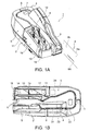
- FIG. 1A is an external oblique view and FIG. 1B is a plan view of a check processing device 1 according to a preferred embodiment of the invention.
- the check processing device 1 has a case 2 on the main unit and a pair of left and right access covers 4 and 5 that open and close pivoting on a vertical support pin 3 disposed at the back end of the case 2.
- a check transportation path 7 for conveying checks 6 is formed between the case 2 and the access covers 4 and 5.
- the check transportation path 7 is a narrow vertical slot that curves in a basically U-shaped configuration when seen from above.
- the upstream end of the check transportation path 7 in the check transportation direction is connected through a check infeed path 8 that is a narrow vertical channel to a check supply unit 9, which is a wide vertical channel.
- the downstream end of the check transportation path 7 is connected to a check storage unit 10.
- the check storage unit 10 has first and second branch paths 11 and 12 connected to the downstream end of the check transportation path 7, and first and second storage pockets 13 and 14 connected to the downstream ends of the first and second branch paths 11 and 12.
- each check 6 has an MICR line 6A printed along the long bottom edge on the front 6a of the check 6. Also recorded on the front 6a against a patterned background are the check amount, payer and payee, various numbers, and the payer signature. An endorsement is recorded on the back 6b of the check 6.
- a front contact image scanner 21 for imaging the fronts of the checks 6 a back contact image scanner 22 for imaging the backs of the checks 6, a magnetic head 23 for reading magnetic ink characters, and a printing mechanism 24 for printing ELECTRONIC FUNDS TRANSFER, for example, on the check front are disposed in this order along the check transportation path 7.
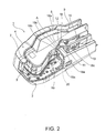
- FIG. 2 is an oblique view of the check processing device with one of the access covers 5 removed.
- the downstream end of the check transportation path 7 is divided into first and second branch paths 11 and 12 by a diversion unit 18. While the transportation path is divided into only two branch paths in this example, there could be three or more branches.
- the diversion unit 18 has right and left diversion unit guide surfaces 18a and 18b, and a diversion unit top 18c connecting the top edges of the diversion unit guide surfaces 18a and 18b.
- the diversion unit guide surfaces 18a and 18b spread apart to the right and left in the downstream branching direction from a vertex at the branching position A between the first and second branch paths 11 and 12.
- the first branch path 11, of which one inside wall is defined by diversion unit guide surface 18a, continues in a straight line from the downstream end of the check transportation path 7.
- the angle is approximately 30 degrees in this embodiment of the invention, but can be any angle less than 90 degrees and is not limited to 30 degrees.
- a switching lever 19 for directing the in-fed check 6 to either one of the first and second branch paths 11 and 12 is disposed at the branching position A.
- the flapper 19 has right and left flapper guide surfaces 19a and 19b that diverge to the right and left in the diversion directions of the first and second branch paths 11 and 12, and a level lever top 19c that covers the top edges of the flapper guide surfaces 19a and 19b.
- the flapper 19 When positioned as seen in FIG. 2 , the flapper 19 closes the upstream end of the second branch path 12 so that a check 6 delivered to the branching position A from the upstream end at the check transportation path 7 is guided by the flapper guide surface 19a and enters the first branch path 11.
- the flapper 19 can also be switched by a switching mechanism 20 disposed below the branching position A to the position closing the upstream end of the first branch path 11.
- a check 6 travelling to the branching position A is guided by the flapper guide surface 19b and enters the second branch path 12.
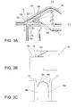
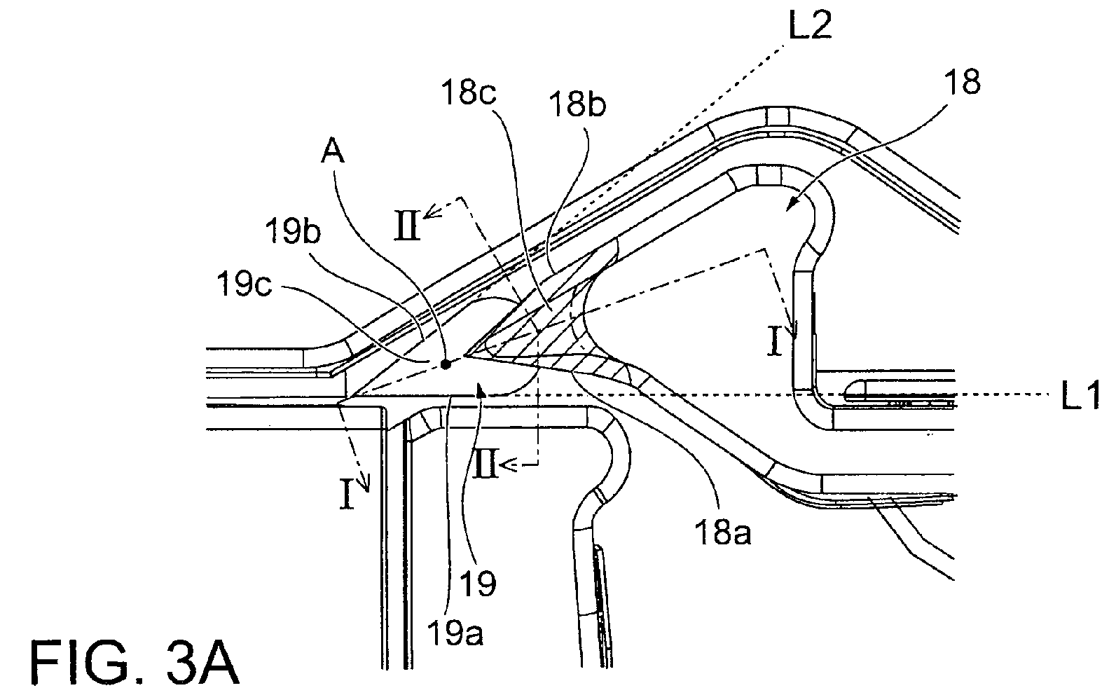
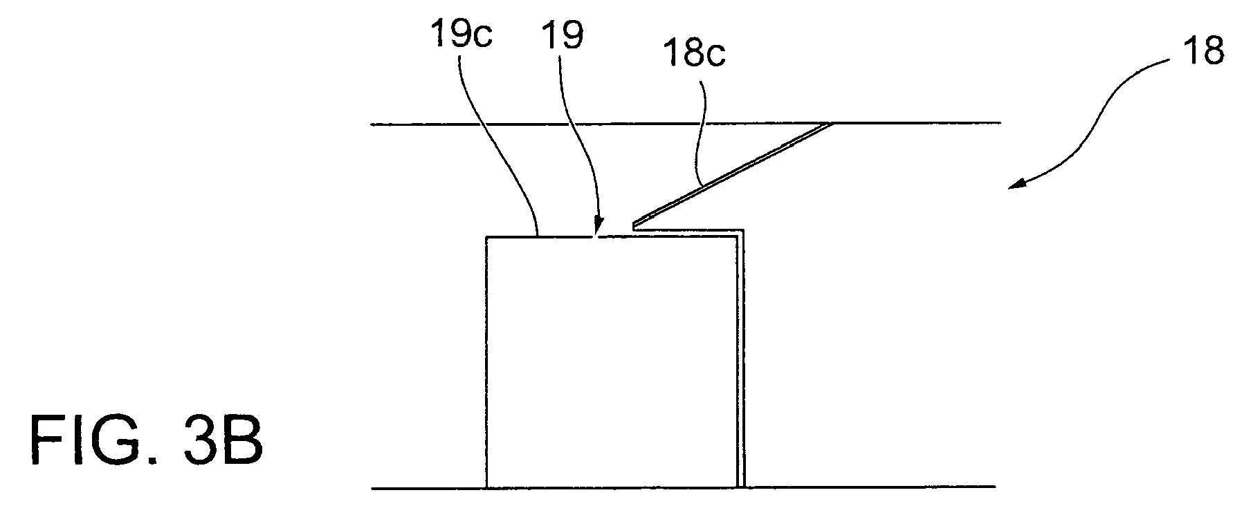
- FIG. 3A is a plan view showing the main parts at the transportation path diversion position.
- FIG. 3B is a section view through line I-I in FIG. 3A
- FIG. 3C is a section view through line II-II in FIG. 3A .
- Line I-I passes through the branching position A and the center between the right and left diversion unit guide surfaces, and line II-II passes through diversion unit top perpendicularly to the direction of each branch path.
- the diversion unit top 18c of the diversion unit 18 slopes upward from the lever top 19c in both left and right diversion directions, and also slopes upward from the top edges of the right and left diversion unit guide surfaces 18a and 18b perpendicularly to the diversion direction.
- the diversion unit top 18c is substantially triangular when seen in plan view, and has an acute angle portion that is defined by the diversion unit guide surfaces 18a and 18b that spread apart to the right and left in the downstream branching direction from a vertex at the branching position A.
- the diversion unit top 18c is finished to a mirror surface.
- the right and left diversion unit guide surfaces 18a and 18b are located to the inside of imaginary lines L1 and L2 extending substantially in the diversion direction of the right and left flapper guide surfaces 19a and 19b of the flapper 19.
- the diversion unit top 18c slopes upward in each of the diversion directions.
- the sectional shape of the diversion unit top 18c perpendicularly to the diversion directions is defined by a convex curved surface that bridges the top edges of the diversion unit guide surfaces 18a and 18b extending in the diversion directions.
- FIG. 4A shows a diversion unit that does not have a diversion unit top as described above
- FIG. 4B shows a diversion unit with the foregoing diversion unit top.
- the diversion unit 18 has a diversion unit top 18c as described above, the drooping portion 6c at the top of the check 6 is guided by the diversion unit top 18c to ride over the diversion unit 18, thereby avoiding a collision between the check 6 and the diversion unit 18.
- the diversion unit top 18c inclines upward in the directions in which the transportation path diverges (the check transportation direction) as well as perpendicularly to the diversion directions.
- the drooping portion 6c of the in-fed check is thereby gradually raised so that it passes over the diversion unit 18.
- the diversion unit top 18c has a mirror finish, the drooping portion 6c of the check 6 is guided smoothly up so that it rides over the diversion unit 18.
- the check 6 guided by the flapper guide surfaces 19a and 19b also does not collide with the diversion unit guide surfaces 18a and 18b.
- the drooping portion of the check is again guided up by the diversion unit top 18c so that it passes over the diversion unit 18.
- the check 6 is thus also prevented from colliding with the diversion unit 18 and jamming when the check 6 enters the first branch path 11.
- the diversion unit top 18c has a convex curved surface when seen in a section view perpendicular to the branching directions of the first and second branch paths 11 and 12, but the diversion unit top 18c could be a flat inclined surface that slopes upward from the top edges of the guide surfaces 18a and 18b of the diversion unit 18.
- check transportation path 7 splits into two branch paths, but the structure of the diversion unit described above for directing checks to the desired branch path can be also be used when the check transportation path 7 splits into three or more branches.
- the diversion unit top 18c is rendered to the diversion unit 18 as a three-dimensionally inclined surface for guiding the drooping portion 6c of a check 6 in the foregoing embodiments, but the lever top 19c of the flapper 19 can be rendered as a three-dimensionally inclined guide surface.
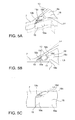
- FIG. 5 shows an example in which the top of the path switching lever (flapper) is rendered as a three-dimensionally inclined guide surface.
- FIG. 5A is an oblique view of the diversion unit area
- FIG. 5B is a plan view of the same
- FIG. 5C is a side view from the side of the flapper and the diversion unit.
- lever top 19c slopes up in the right and left diversion directions while also sloping up from the top edges of the flapper guide surfaces 19a and 19b substantially perpendicularly to the directions in which the branch path diverges. More particularly, the lever top 19c is shaped similarly to the diversion unit top 18c described above.
- top of the flapper is thus rendered as a three-dimensionally inclined guide surface and the right and left guide surfaces 18a and 18b of the diversion unit 18 are positioned set back to the inside from imaginary lines L3 and L4 extending substantially in the diversion direction of the right and left guide surfaces 19a and 19b of the flapper 19, a check 6 guided by the flapper guide surfaces 19a and 19b can be prevented from colliding with the diversion unit guide surfaces 18a and 18b.
- the edge 18d of the diversion unit top 18c facing the flapper 19 is positioned below an imaginary line L5 extending the lever top 19c in the diversion direction, a check 6 guided by the lever top 19c can be prevented from colliding with the diversion unit top 18c.
Landscapes
- Engineering & Computer Science (AREA)
- Mechanical Engineering (AREA)
- Separation, Sorting, Adjustment, Or Bending Of Sheets To Be Conveyed (AREA)
Abstract
Description
- The present invention relates to a sheet media processing device that has a mechanism for distributing sheet media conveyed from a transportation path into one of a plurality of diversion paths. The invention relates more particularly to a diversion mechanism for the sheet media processing device that routes the sheet media to the desired path without the media jamming. The invention also relates to a media processing device that has this diversion mechanism.
- Stores as well as banks and other financial institutions commonly use check processing devices (also referred to as a "check reader" or "check scanner") to image and read magnetic ink characters from financial instruments such as checks presented by customers. The captured image data and magnetic ink character information is also computer processed for transaction processing. However, the magnetic ink characters required for transaction processing cannot be read from some presented checks. The check processing device therefore stores the checks from which the magnetic ink characters cannot be read in a separate media storage unit.
- The check processing device processes checks while conveying the checks standing on edge through a transportation path rendered as a narrow vertical slot-like channel. The downstream end of the transportation path branches into left and right channels into which the checks are directed at the junction with the main transportation path, and a media storage unit is disposed at the downstream end of both branch paths. A path-switching lever, or flapper, that directs the checks conveyed thereto into one of the branch paths is disposed at the junction where the paths diverge. See, for example, Japanese Unexamined Patent Appl. Pub.
JP-A-2004-206362 - The width of the most commonly used check sizes ranges from 60 to 125 mm. When a wide (tall) check is loaded into the check processing device, the top part of the check typically protrudes above the top of the transportation path, and the protruding part of the check may be rather large. This can result in the exposed top part of the check drooping to one side as the check is conveyed through the transportation path. In addition, if a check that has been crumpled or wrinkled or that has lost its stiffness is loaded into the check processing device, the top part of the check exposed from the top of the transportation path may also droop to the side even if the check is not particularly wide. When a check that thus droops to the side for any reason is fed to the diversion point of the transportation path, the portion of the check that hangs to the side collides with the diversion mechanism and causes the check to jam.
- A problem with the related art is thus that when an edge portion of the check is drooping or bent over and this bent portion of the check collides with the diversion unit of the transportation path, the check may become jammed.
- The diversion mechanism of a sheet media processing device according to the present invention enables a check to enter a branch path without colliding with the diversion unit. Another aspect of the invention is a media processing device that has the diversion mechanism of the invention.
- A diversion mechanism for a sheet media processing device, the diversion mechanism having a diversion unit that splits a sheet media transportation path into right and left branch paths, and a branch switching lever that directs sheet media conveyed to the branch path diversion position into one of the branch paths. The diversion unit has left and right diversion unit guide surfaces that spread apart in the left and right diversion directions, and a diversion unit top that connects the top edges of the diversion unit guide surfaces. The branch switching lever has left and right lever-side guide surfaces that spread apart in the left and right diversion directions, and a lever top that connects the top edges of the lever-side guide surfaces. The diversion unit top slopes upward in the left and right diversion directions from the lever top, and slopes upward perpendicularly to the diversion directions from the top edges of the left and right diversion unit guide surfaces.
- In this aspect of the invention the diversion unit has a top that slopes in three dimensions above the branch switching lever. As a result, if the top part of the sheet medium is drooping to one side when the sheet medium enters one of the branch paths, this drooping top part of the sheet medium is guided by this diversion unit top to ride over the diversion unit. The sheet medium therefore avoids colliding with the end of the diversion unit as the sheet medium enters the branch path, and the sheet medium can therefore enter the branch path without jamming.
- In order to guide the drooping part of the sheet medium upward perpendicularly to the diversion direction, the shape of the diversion unit top perpendicularly to the diversion direction is preferably a convex curve when seen in section view.
- Further preferably, the diversion unit top has a mirror-surface finish in order to guide the drooping part of the sheet medium smoothly. Further preferably, the left and right guide surfaces of the diversion unit diverge at an angle less than 90 degrees.
- Yet further preferably, the left and right diversion unit guide surfaces are positioned set back to the inside from imaginary lines extending the left and right lever-side guide surfaces in the diversion directions so that the sheet medium guided into a branch path by a lever-side guide surface does not collide with the diverting guide surface of the diversion unit.
- A diversion mechanism according to another aspect of the invention for a sheet media processing device has a diversion unit that splits a sheet media transportation path into at least two branch paths, and a branch switching lever that directs sheet media conveyed to the branch path diversion position into one of the branch paths. The diversion unit has diversion unit guide surfaces that spread apart in the diversion direction, and a diversion unit top that connects the top edges of the diversion unit guide surfaces. The branch switching lever has lever-side guide surfaces that spread apart substantially in the diversion direction, and a lever top that connects the top edges of the lever-side guide surfaces. The lever top slopes upward in the diversion direction, and slopes upward perpendicularly to the diversion direction from the top edges of the lever-side guide surfaces. The diversion unit guide surfaces are positioned set back to the inside from imaginary lines extending the lever-side guide surfaces in the diversion directions, and the edge portion of the diversion unit top on the branch switching lever side is positioned below an imaginary line extending the lever top in the diversion direction.
- In this aspect of the invention the branch switching lever has a top that slopes in three dimensions. The edges of the left and right diversion unit guide surfaces and the diversion unit top are also set back from the plane of the lever-side guide surfaces and the lever top. As a result, if the top part of the sheet medium is drooping to one side when the sheet medium enters one of the branch paths, this drooping top part of the sheet medium is guided by this lever top to ride up and over the diversion unit. The sheet medium can therefore enter the selected diversion path without jamming because the diverted sheet medium entering the branch path is prevented from colliding with the end of the diversion unit.
- Another aspect of the invention is a media processing device having a diversion mechanism that has a diversion unit that splits a media transportation path into at least two branch paths, and a branch switching lever that directs media conveyed to the branch path diversion position into one of the branch paths. The diversion unit has diversion unit guide surfaces that spread apart in the diversion direction, and a diversion unit top that connects the top edges of the diversion unit guide surfaces. The branch switching lever has lever-side guide surfaces that spread apart in the diversion direction, and a lever top that connects the top edges of the lever-side guide surfaces. The diversion unit top slopes upward in the diversion direction from the media transportation direction side, and slopes upward perpendicularly to the diversion direction from the top edges of the diversion unit guide surfaces.
- If the top part of a sheet medium is drooping to the side when the sheet medium is guided into one of the branch paths, the diversion mechanism for a sheet media processing device according to the present invention guides the drooping part of the medium up and along the top of the diversion unit so that the drooping portion of the medium rides over the diversion unit. As a result, the sheet medium can be prevented from colliding with the end of the diversion unit when the sheet medium enters one of the branch paths, and can therefore travel unimpeded into the branch path without becoming jammed.
- In the diversion mechanism according to another aspect of the invention, the branch switching lever has a top that slopes in three dimensions. The edges of the left and right diversion unit guide surfaces and the diversion unit top are also set back from the plane of the lever-side guide surfaces and the lever top. As a result, if the top part of the sheet medium is drooping to one side when the sheet medium enters one of the branch paths, this drooping top part of the sheet medium is guided by this lever top to ride up and over the diversion unit. The sheet medium can therefore enter the selected diversion path without jamming because the diverted sheet medium entering the branch path is prevented from colliding with the end of the diversion unit.
- Other objects and attainments together with a fuller understanding of the invention will become apparent and appreciated by referring to the following description and claims taken in conjunction with the accompanying drawings.
-
-
FIG. 1 is an oblique external view of a check processing device according to the present invention. -
FIG. 2 is an oblique view of the check processing device with one of the access covers removed. -
FIG. 3 is a plan view and a section view showing the main parts at the diverter position. -
FIG. 4 describes the operation guiding a check into the second branch path when the top of the check is drooping to the side. -
FIG. 5 is an oblique view showing another example of the diversion mechanism according to the present invention. - A preferred embodiment of a check processing device having a diversion mechanism according to the present invention is described below with reference to the accompanying figures.
-
FIG. 1A is an external oblique view andFIG. 1B is a plan view of acheck processing device 1 according to a preferred embodiment of the invention. - The
check processing device 1 has acase 2 on the main unit and a pair of left and right access covers 4 and 5 that open and close pivoting on avertical support pin 3 disposed at the back end of thecase 2. Acheck transportation path 7 for conveyingchecks 6 is formed between thecase 2 and the access covers 4 and 5. - The
check transportation path 7 is a narrow vertical slot that curves in a basically U-shaped configuration when seen from above. The upstream end of thecheck transportation path 7 in the check transportation direction is connected through acheck infeed path 8 that is a narrow vertical channel to acheck supply unit 9, which is a wide vertical channel. The downstream end of thecheck transportation path 7 is connected to acheck storage unit 10. - The
check storage unit 10 has first andsecond branch paths check transportation path 7, and first and second storage pockets 13 and 14 connected to the downstream ends of the first andsecond branch paths - As shown in
FIG. 1 , eachcheck 6 has anMICR line 6A printed along the long bottom edge on the front 6a of thecheck 6. Also recorded on the front 6a against a patterned background are the check amount, payer and payee, various numbers, and the payer signature. An endorsement is recorded on the back 6b of thecheck 6. - As indicated by the dotted lines in
FIG. 1B , a frontcontact image scanner 21 for imaging the fronts of thechecks 6, a backcontact image scanner 22 for imaging the backs of thechecks 6, amagnetic head 23 for reading magnetic ink characters, and aprinting mechanism 24 for printing ELECTRONIC FUNDS TRANSFER, for example, on the check front are disposed in this order along thecheck transportation path 7. - After a
check 6 is delivered from thecheck supply unit 9 through thecheck infeed path 8, the front and back sides of thecheck 6 are imaged and the magneticink character line 6A printed on thecheck front 6a is read as thecheck 6 travels through thecheck transportation path 7. If the information is read correctly, ELECTRONIC FUNDS TRANSFER or other information is printed on thecheck 6, and thecheck 6 is delivered to and stored in thefirst storage pocket 13.Checks 6 that cannot be scanned or read correctly are not printed and are diverted to and stored in thesecond storage pocket 14. -
FIG. 2 is an oblique view of the check processing device with one of the access covers 5 removed. - The downstream end of the
check transportation path 7 is divided into first andsecond branch paths diversion unit 18. While the transportation path is divided into only two branch paths in this example, there could be three or more branches. Thediversion unit 18 has right and left diversion unit guide surfaces 18a and 18b, and adiversion unit top 18c connecting the top edges of the diversion unit guide surfaces 18a and 18b. The diversion unit guide surfaces 18a and 18b spread apart to the right and left in the downstream branching direction from a vertex at the branching position A between the first andsecond branch paths - The
first branch path 11, of which one inside wall is defined by diversionunit guide surface 18a, continues in a straight line from the downstream end of thecheck transportation path 7. - The
second branch path 12, of which one inside wall is defined byside guide surface 18b, branches at an angle of less than 90 degrees from thefirst branch path 11. The angle is approximately 30 degrees in this embodiment of the invention, but can be any angle less than 90 degrees and is not limited to 30 degrees. - A switching lever 19 (flapper) for directing the in-fed
check 6 to either one of the first andsecond branch paths flapper 19 has right and left flapper guide surfaces 19a and 19b that diverge to the right and left in the diversion directions of the first andsecond branch paths level lever top 19c that covers the top edges of the flapper guide surfaces 19a and 19b. - When positioned as seen in
FIG. 2 , theflapper 19 closes the upstream end of thesecond branch path 12 so that acheck 6 delivered to the branching position A from the upstream end at thecheck transportation path 7 is guided by theflapper guide surface 19a and enters thefirst branch path 11. Theflapper 19 can also be switched by aswitching mechanism 20 disposed below the branching position A to the position closing the upstream end of thefirst branch path 11. When theflapper 19 is thus switched, acheck 6 travelling to the branching position A is guided by theflapper guide surface 19b and enters thesecond branch path 12. -
FIG. 3A is a plan view showing the main parts at the transportation path diversion position.FIG. 3B is a section view through line I-I inFIG. 3A, and FIG. 3C is a section view through line II-II inFIG. 3A . Line I-I passes through the branching position A and the center between the right and left diversion unit guide surfaces, and line II-II passes through diversion unit top perpendicularly to the direction of each branch path. - The
diversion unit top 18c of thediversion unit 18 slopes upward from thelever top 19c in both left and right diversion directions, and also slopes upward from the top edges of the right and left diversion unit guide surfaces 18a and 18b perpendicularly to the diversion direction. - As shown in
FIG. 3A , thediversion unit top 18c is substantially triangular when seen in plan view, and has an acute angle portion that is defined by the diversion unit guide surfaces 18a and 18b that spread apart to the right and left in the downstream branching direction from a vertex at the branching position A. Thediversion unit top 18c is finished to a mirror surface. The right and left diversion unit guide surfaces 18a and 18b are located to the inside of imaginary lines L1 and L2 extending substantially in the diversion direction of the right and left flapper guide surfaces 19a and 19b of theflapper 19. - As shown in
FIG. 3B , thediversion unit top 18c slopes upward in each of the diversion directions. As shown inFIG. 3C , the sectional shape of thediversion unit top 18c perpendicularly to the diversion directions is defined by a convex curved surface that bridges the top edges of the diversion unit guide surfaces 18a and 18b extending in the diversion directions. - The effect of the diversion mechanism rendered by the diversion unit having the foregoing diversion unit top is described below with reference to
FIG. 4. FIG. 4A shows a diversion unit that does not have a diversion unit top as described above, andFIG. 4B shows a diversion unit with the foregoing diversion unit top. - When the top of the
diversion unit 18 is flat as shown inFIG. 4A and acheck 6 is directed into thesecond branch path 12, the droopingportion 6c at the top of thecheck 6 collides with the distal end of thediversion unit 18. - As shown in
FIG. 4B , however, when thediversion unit 18 has adiversion unit top 18c as described above, the droopingportion 6c at the top of thecheck 6 is guided by thediversion unit top 18c to ride over thediversion unit 18, thereby avoiding a collision between thecheck 6 and thediversion unit 18. - More particularly, the
diversion unit top 18c inclines upward in the directions in which the transportation path diverges (the check transportation direction) as well as perpendicularly to the diversion directions. The droopingportion 6c of the in-fed check is thereby gradually raised so that it passes over thediversion unit 18. - In addition, because the
diversion unit top 18c has a mirror finish, the droopingportion 6c of thecheck 6 is guided smoothly up so that it rides over thediversion unit 18. - Furthermore, because the right and left diversion unit guide surfaces 18a and 18b are set back from the right and left flapper guide surfaces 19a and 19b of the
flapper 19, thecheck 6 guided by the flapper guide surfaces 19a and 19b also does not collide with the diversion unit guide surfaces 18a and 18b. - If the top part of the
check 6 droops over to thesecond branch path 12 side when thecheck 6 is guided into thefirst branch path 11, the drooping portion of the check is again guided up by thediversion unit top 18c so that it passes over thediversion unit 18. Thecheck 6 is thus also prevented from colliding with thediversion unit 18 and jamming when thecheck 6 enters thefirst branch path 11. - In the embodiment described above the
diversion unit top 18c has a convex curved surface when seen in a section view perpendicular to the branching directions of the first andsecond branch paths diversion unit top 18c could be a flat inclined surface that slopes upward from the top edges of the guide surfaces 18a and 18b of thediversion unit 18. - In the embodiments described above the
check transportation path 7 splits into two branch paths, but the structure of the diversion unit described above for directing checks to the desired branch path can be also be used when thecheck transportation path 7 splits into three or more branches. - The
diversion unit top 18c is rendered to thediversion unit 18 as a three-dimensionally inclined surface for guiding the droopingportion 6c of acheck 6 in the foregoing embodiments, but thelever top 19c of theflapper 19 can be rendered as a three-dimensionally inclined guide surface. -
FIG. 5 shows an example in which the top of the path switching lever (flapper) is rendered as a three-dimensionally inclined guide surface.FIG. 5A is an oblique view of the diversion unit area,FIG. 5B is a plan view of the same, andFIG. 5C is a side view from the side of the flapper and the diversion unit. - In this configuration the
lever top 19c slopes up in the right and left diversion directions while also sloping up from the top edges of the flapper guide surfaces 19a and 19b substantially perpendicularly to the directions in which the branch path diverges. More particularly, thelever top 19c is shaped similarly to thediversion unit top 18c described above. - If the top of the flapper is thus rendered as a three-dimensionally inclined guide surface and the right and left guide surfaces 18a and 18b of the
diversion unit 18 are positioned set back to the inside from imaginary lines L3 and L4 extending substantially in the diversion direction of the right and left guide surfaces 19a and 19b of theflapper 19, acheck 6 guided by the flapper guide surfaces 19a and 19b can be prevented from colliding with the diversion unit guide surfaces 18a and 18b. In addition, if theedge 18d of thediversion unit top 18c facing theflapper 19 is positioned below an imaginary line L5 extending thelever top 19c in the diversion direction, acheck 6 guided by thelever top 19c can be prevented from colliding with thediversion unit top 18c. - Although the present invention has been described in connection with the preferred embodiments thereof with reference to the accompanying drawings, it is to be noted that various changes and modifications will be apparent to those skilled in the art. Such changes and modifications are to be understood as included within the scope of the present invention as defined by the appended claims, unless they depart therefrom.
Claims (11)
- A diversion mechanism for a sheet media processing device, comprising:a diversion unit (18) that splits a sheet media transportation path into right and left branch paths (11, 12); anda branch switching lever (19) adapted to direct sheet media conveyed to a branch path diversion position into one of the branch paths (11, 12); whereinthe diversion unit (18) has left and right diversion unit guide surfaces (18a, 18b) that spread apart in a left and a right diversion direction, and a diversion unit top (18c) that connects the top edges of the diversion unit guide surfaces (18a, 18b);the branch switching lever (19) has left and right lever-side guide surfaces (19a, 19b) that spread apart in the left and right diversion directions, and a lever top (19c) that connects the top edges of the lever-side guide surfaces (19a, 19b); andthe diversion unit top (18c) slopes upward in the left and right diversion directions from the lever top (19c), and slopes upward perpendicularly to the diversion directions from the top edges of the left and right diversion unit guide surfaces (18a, 18b).
- The diversion mechanism of claim 1, wherein, in sectional view, the shape of the diversion unit top (18c) perpendicularly to the diversion directions is a convex curve.
- The diversion mechanism of claim 1 or 2, wherein the diversion unit top (18c) has a mirror-surface finish.
- The diversion mechanism of any one of the preceding claims, wherein the left and right diversion unit guide surfaces (18a, 18b) of the diversion unit (18) diverge at an angle less than 90 degrees.
- The diversion mechanism of any one of the preceding claims, wherein the left and right diversion unit guide surfaces (18a, 18b) are positioned set back to the inside from imaginary lines extending the left and right lever-side guide surfaces (19a, 19b) in the diversion directions.
- A diversion mechanism for a sheet media processing device, comprising:a diversion unit (18) that splits a sheet media transportation path into at least two branch paths (11, 12); anda branch switching lever (19) that directs sheet media conveyed to the branch path diversion position into one of the branch paths (11, 12);wherein the diversion unit (18) has diversion unit guide surfaces (18a, 18b) that spread apart in the diversion direction, anda diversion unit top (18c) that connects the top edges of the diversion unit guide surfaces (18a, 18b);the branch switching lever (19) has lever-side guide surfaces (19a, 19b) that spread apart substantially in the diversion direction, anda lever top (19c) that connects the top edges of the lever-side guide surfaces (19a, 19b); andthe lever top (19c) slopes upward in the diversion direction, and slopes upward perpendicularly to the diversion direction from the top edges of the lever-side guide surfaces (19a, 19b);the diversion unit guide surfaces (18a, 18b) are positioned set back to the inside from imaginary lines extending the lever-side guide surfaces (19a, 19b) in the diversion directions; andthe edge portion of the diversion unit top (18c) on the branch switching lever side is positioned below an imaginary line extending the lever top (19c) in the diversion direction.
- A media processing device comprising a diversion mechanism that has a diversion unit (18) that splits a media transportation path into at least two branch paths (11, 12), and a branch switching lever (19) that directs media conveyed to the branch path diversion position into one of the branch paths (11, 12);
wherein the diversion unit (18) has diversion unit guide surfaces (18a, 18b) that spread apart in the diversion direction, anda diversion unit top (18c) that connects the top edges of the diversion unit guide surfaces (18a, 18b);the branch switching lever (19) has lever-side guide surfaces (19a, 19b) that spread apart in the diversion direction, anda lever top (19c) that connects the top edges of the lever-side guide surfaces (19a, 19b); andthe diversion unit top (18c) slopes upward in the diversion direction from the media transportation direction side, and slopes upward perpendicularly to the diversion direction from the top edges of the diversion unit guide surfaces (18a, 18b). - The media processing device described in claim 7, wherein:the shape of the diversion unit top (18c) perpendicularly to the diversion directions is a convex curve when seen in section view.
- The media processing device described in claim 7, wherein:the diversion unit top (18c) has a mirror-surface finish.
- The media processing device described in claim 7, wherein:the diversion unit guide surfaces (18a, 18b) of the diversion unit (18) diverge at an angle less than 90 degrees.
- The media processing device described in claim 7, wherein:the diversion unit guide surfaces (18a, 18b) are positioned set back to the inside from imaginary lines extending the lever-side guide surfaces (19a, 19b) in the diversion directions.
Applications Claiming Priority (1)
| Application Number | Priority Date | Filing Date | Title |
|---|---|---|---|
| JP2007186607A JP4905276B2 (en) | 2007-07-18 | 2007-07-18 | Branch structure of sheet medium processing apparatus and sheet medium processing apparatus |
Publications (3)
| Publication Number | Publication Date |
|---|---|
| EP2017208A2 true EP2017208A2 (en) | 2009-01-21 |
| EP2017208A3 EP2017208A3 (en) | 2009-08-05 |
| EP2017208B1 EP2017208B1 (en) | 2014-03-12 |
Family
ID=39870026
Family Applications (1)
| Application Number | Title | Priority Date | Filing Date |
|---|---|---|---|
| EP08012907.5A Not-in-force EP2017208B1 (en) | 2007-07-18 | 2008-07-17 | Media diversion mechanism for a sheet media processing device |
Country Status (4)
| Country | Link |
|---|---|
| US (1) | US7988151B2 (en) |
| EP (1) | EP2017208B1 (en) |
| JP (1) | JP4905276B2 (en) |
| ES (1) | ES2462742T3 (en) |
Families Citing this family (3)
| Publication number | Priority date | Publication date | Assignee | Title |
|---|---|---|---|---|
| FR2983842B1 (en) * | 2011-12-13 | 2014-07-04 | Solystic | CONVEYING DEVICE FOR FLAT OBJECTS ON SINGING AND POSTAL SORTING MACHINE |
| CN103632432B (en) * | 2012-08-24 | 2016-04-20 | 山东新北洋信息技术股份有限公司 | Check treatment facility |
| CN106373261B (en) * | 2016-10-17 | 2022-08-30 | 深圳怡化电脑股份有限公司 | Banknote guide device |
Citations (1)
| Publication number | Priority date | Publication date | Assignee | Title |
|---|---|---|---|---|
| JP2004206362A (en) | 2002-12-25 | 2004-07-22 | Canon Electronics Inc | Reader for checks |
Family Cites Families (10)
| Publication number | Priority date | Publication date | Assignee | Title |
|---|---|---|---|---|
| BE623146A (en) * | 1961-10-11 | 1900-01-01 | ||
| IT1059759B (en) | 1975-05-30 | 1982-06-21 | Licentia Gmbh | DISTRIBUTOR CONVEYOR DEVICE |
| US4913295A (en) | 1985-04-08 | 1990-04-03 | Banctec, Inc. | Apparatus for processing remittance and remittance advice documents |
| FR2677003B1 (en) | 1991-05-30 | 1993-10-01 | Bertin Et Cie | DEVICE FOR MOVING A MOBILE PART BETWEEN FIRST AND SECOND POSITIONS AND HOLDING IT IN EACH OF THESE POSITIONS. |
| JPH0733307A (en) | 1993-07-16 | 1995-02-03 | Omron Corp | Check processor |
| JP4064137B2 (en) * | 2002-03-28 | 2008-03-19 | グローリー株式会社 | Banknote handling equipment |
| US20040144697A1 (en) | 2003-01-24 | 2004-07-29 | Roland Ramonowski | Diverter gate with wear attachment |
| JP4349259B2 (en) * | 2003-11-10 | 2009-10-21 | セイコーエプソン株式会社 | Image reading apparatus and composite processing apparatus provided with image reading apparatus |
| JP4720161B2 (en) | 2004-12-01 | 2011-07-13 | セイコーエプソン株式会社 | Composite processing apparatus and control method thereof |
| JP4837592B2 (en) * | 2006-05-29 | 2011-12-14 | 株式会社リコー | RECORDING MEDIUM CONVEYING DEVICE AND IMAGE FORMING DEVICE |
-
2007
- 2007-07-18 JP JP2007186607A patent/JP4905276B2/en not_active Expired - Fee Related
-
2008
- 2008-07-16 US US12/218,513 patent/US7988151B2/en active Active
- 2008-07-17 ES ES08012907.5T patent/ES2462742T3/en active Active
- 2008-07-17 EP EP08012907.5A patent/EP2017208B1/en not_active Not-in-force
Patent Citations (1)
| Publication number | Priority date | Publication date | Assignee | Title |
|---|---|---|---|---|
| JP2004206362A (en) | 2002-12-25 | 2004-07-22 | Canon Electronics Inc | Reader for checks |
Also Published As
| Publication number | Publication date |
|---|---|
| EP2017208A3 (en) | 2009-08-05 |
| US20090184465A1 (en) | 2009-07-23 |
| JP4905276B2 (en) | 2012-03-28 |
| EP2017208B1 (en) | 2014-03-12 |
| ES2462742T3 (en) | 2014-05-26 |
| US7988151B2 (en) | 2011-08-02 |
| JP2009023759A (en) | 2009-02-05 |
Similar Documents
| Publication | Publication Date | Title |
|---|---|---|
| US7827710B2 (en) | Card for retaining items therein | |
| JP4321230B2 (en) | Data reader | |
| AP1742A (en) | Smart documents. | |
| EP2017208B1 (en) | Media diversion mechanism for a sheet media processing device | |
| JP4770757B2 (en) | Medium delivery apparatus and medium processing apparatus | |
| US9519846B2 (en) | Card reader | |
| JP5647798B2 (en) | Paper handling equipment | |
| CN103426233B (en) | Medium collection device and media processing apparatus | |
| EP3051465B1 (en) | Card reader | |
| KR102010314B1 (en) | Card processing unit, automatic trading unit | |
| JP5033606B2 (en) | Card transport mechanism | |
| CN106233343A (en) | Media processing device and automatic transaction device | |
| US11797964B2 (en) | Automated transaction machine | |
| JP2008165483A (en) | Card collection mechanism and card issuing device | |
| JP4323329B2 (en) | Card reader | |
| JP2008021140A (en) | Paper sheet handling equipment | |
| JP2017123128A (en) | Card processor | |
| US7717345B2 (en) | Media processing device | |
| US20090039596A1 (en) | Sheet media storage device and sheet media processing device | |
| JP2009029537A (en) | Sheet storage device and medium processing device | |
| CN106056791B (en) | Medium conveying apparatus and medium transaction device | |
| JP5397041B2 (en) | Media insertion part | |
| JP6916147B2 (en) | Paper leaf reader and paper leaf discharge method | |
| JP4967877B2 (en) | Sheet medium storage device | |
| JP2025100147A (en) | Panel unit mounting structure and device |
Legal Events
| Date | Code | Title | Description |
|---|---|---|---|
| PUAI | Public reference made under article 153(3) epc to a published international application that has entered the european phase |
Free format text: ORIGINAL CODE: 0009012 |
|
| AK | Designated contracting states |
Kind code of ref document: A2 Designated state(s): AT BE BG CH CY CZ DE DK EE ES FI FR GB GR HR HU IE IS IT LI LT LU LV MC MT NL NO PL PT RO SE SI SK TR |
|
| AX | Request for extension of the european patent |
Extension state: AL BA MK RS |
|
| PUAL | Search report despatched |
Free format text: ORIGINAL CODE: 0009013 |
|
| AK | Designated contracting states |
Kind code of ref document: A3 Designated state(s): AT BE BG CH CY CZ DE DK EE ES FI FR GB GR HR HU IE IS IT LI LT LU LV MC MT NL NO PL PT RO SE SI SK TR |
|
| AX | Request for extension of the european patent |
Extension state: AL BA MK RS |
|
| 17P | Request for examination filed |
Effective date: 20091201 |
|
| AKX | Designation fees paid |
Designated state(s): DE ES FR GB IT |
|
| 17Q | First examination report despatched |
Effective date: 20110323 |
|
| GRAP | Despatch of communication of intention to grant a patent |
Free format text: ORIGINAL CODE: EPIDOSNIGR1 |
|
| INTG | Intention to grant announced |
Effective date: 20131126 |
|
| GRAS | Grant fee paid |
Free format text: ORIGINAL CODE: EPIDOSNIGR3 |
|
| GRAA | (expected) grant |
Free format text: ORIGINAL CODE: 0009210 |
|
| AK | Designated contracting states |
Kind code of ref document: B1 Designated state(s): DE ES FR GB IT |
|
| REG | Reference to a national code |
Ref country code: GB Ref legal event code: FG4D |
|
| REG | Reference to a national code |
Ref country code: DE Ref legal event code: R096 Ref document number: 602008030727 Country of ref document: DE Effective date: 20140424 |
|
| REG | Reference to a national code |
Ref country code: ES Ref legal event code: FG2A Ref document number: 2462742 Country of ref document: ES Kind code of ref document: T3 Effective date: 20140526 |
|
| REG | Reference to a national code |
Ref country code: DE Ref legal event code: R097 Ref document number: 602008030727 Country of ref document: DE |
|
| PLBE | No opposition filed within time limit |
Free format text: ORIGINAL CODE: 0009261 |
|
| STAA | Information on the status of an ep patent application or granted ep patent |
Free format text: STATUS: NO OPPOSITION FILED WITHIN TIME LIMIT |
|
| 26N | No opposition filed |
Effective date: 20141215 |
|
| REG | Reference to a national code |
Ref country code: DE Ref legal event code: R097 Ref document number: 602008030727 Country of ref document: DE Effective date: 20141215 |
|
| REG | Reference to a national code |
Ref country code: FR Ref legal event code: PLFP Year of fee payment: 9 |
|
| REG | Reference to a national code |
Ref country code: FR Ref legal event code: PLFP Year of fee payment: 10 |
|
| REG | Reference to a national code |
Ref country code: FR Ref legal event code: PLFP Year of fee payment: 11 |
|
| PGFP | Annual fee paid to national office [announced via postgrant information from national office to epo] |
Ref country code: IT Payment date: 20220613 Year of fee payment: 15 Ref country code: GB Payment date: 20220606 Year of fee payment: 15 |
|
| PGFP | Annual fee paid to national office [announced via postgrant information from national office to epo] |
Ref country code: FR Payment date: 20220609 Year of fee payment: 15 |
|
| PGFP | Annual fee paid to national office [announced via postgrant information from national office to epo] |
Ref country code: ES Payment date: 20220801 Year of fee payment: 15 Ref country code: DE Payment date: 20220531 Year of fee payment: 15 |
|
| REG | Reference to a national code |
Ref country code: DE Ref legal event code: R119 Ref document number: 602008030727 Country of ref document: DE |
|
| GBPC | Gb: european patent ceased through non-payment of renewal fee |
Effective date: 20230717 |
|
| PG25 | Lapsed in a contracting state [announced via postgrant information from national office to epo] |
Ref country code: DE Free format text: LAPSE BECAUSE OF NON-PAYMENT OF DUE FEES Effective date: 20240201 Ref country code: GB Free format text: LAPSE BECAUSE OF NON-PAYMENT OF DUE FEES Effective date: 20230717 |
|
| PG25 | Lapsed in a contracting state [announced via postgrant information from national office to epo] |
Ref country code: FR Free format text: LAPSE BECAUSE OF NON-PAYMENT OF DUE FEES Effective date: 20230731 |
|
| PG25 | Lapsed in a contracting state [announced via postgrant information from national office to epo] |
Ref country code: IT Free format text: LAPSE BECAUSE OF NON-PAYMENT OF DUE FEES Effective date: 20230717 |
|
| REG | Reference to a national code |
Ref country code: ES Ref legal event code: FD2A Effective date: 20240830 |
|
| PG25 | Lapsed in a contracting state [announced via postgrant information from national office to epo] |
Ref country code: ES Free format text: LAPSE BECAUSE OF NON-PAYMENT OF DUE FEES Effective date: 20230718 |
|
| PG25 | Lapsed in a contracting state [announced via postgrant information from national office to epo] |
Ref country code: ES Free format text: LAPSE BECAUSE OF NON-PAYMENT OF DUE FEES Effective date: 20230718 |