EP2017229A1 - Wasserbehandlungsvorrichtung und Wasserbehandlungsverfahren - Google Patents
Wasserbehandlungsvorrichtung und Wasserbehandlungsverfahren Download PDFInfo
- Publication number
- EP2017229A1 EP2017229A1 EP08012963A EP08012963A EP2017229A1 EP 2017229 A1 EP2017229 A1 EP 2017229A1 EP 08012963 A EP08012963 A EP 08012963A EP 08012963 A EP08012963 A EP 08012963A EP 2017229 A1 EP2017229 A1 EP 2017229A1
- Authority
- EP
- European Patent Office
- Prior art keywords
- electrode
- water
- treated
- oxidant
- water treatment
- Prior art date
- Legal status (The legal status is an assumption and is not a legal conclusion. Google has not performed a legal analysis and makes no representation as to the accuracy of the status listed.)
- Withdrawn
Links
- XLYOFNOQVPJJNP-UHFFFAOYSA-N water Substances O XLYOFNOQVPJJNP-UHFFFAOYSA-N 0.000 title claims abstract description 451
- 238000011282 treatment Methods 0.000 title claims abstract description 237
- 238000000034 method Methods 0.000 title claims description 46
- 239000000835 fiber Substances 0.000 claims abstract description 149
- 239000007800 oxidant agent Substances 0.000 claims abstract description 118
- 230000001590 oxidative effect Effects 0.000 claims abstract description 115
- QWPPOHNGKGFGJK-UHFFFAOYSA-N hypochlorous acid Chemical compound ClO QWPPOHNGKGFGJK-UHFFFAOYSA-N 0.000 claims abstract description 100
- 239000000126 substance Substances 0.000 claims abstract description 20
- 238000011144 upstream manufacturing Methods 0.000 claims abstract description 13
- ZAMOUSCENKQFHK-UHFFFAOYSA-N Chlorine atom Chemical compound [Cl] ZAMOUSCENKQFHK-UHFFFAOYSA-N 0.000 claims description 66
- 239000000460 chlorine Substances 0.000 claims description 66
- 229910052801 chlorine Inorganic materials 0.000 claims description 66
- 230000001954 sterilising effect Effects 0.000 claims description 29
- MHAJPDPJQMAIIY-UHFFFAOYSA-N Hydrogen peroxide Chemical compound OO MHAJPDPJQMAIIY-UHFFFAOYSA-N 0.000 claims description 18
- CBENFWSGALASAD-UHFFFAOYSA-N Ozone Chemical compound [O-][O+]=O CBENFWSGALASAD-UHFFFAOYSA-N 0.000 claims description 16
- 238000000354 decomposition reaction Methods 0.000 claims description 11
- 230000001105 regulatory effect Effects 0.000 claims description 7
- 239000011230 binding agent Substances 0.000 claims description 6
- 125000006850 spacer group Chemical group 0.000 description 35
- 238000002474 experimental method Methods 0.000 description 21
- 229920000049 Carbon (fiber) Polymers 0.000 description 19
- 239000004917 carbon fiber Substances 0.000 description 19
- 238000004659 sterilization and disinfection Methods 0.000 description 19
- 239000008399 tap water Substances 0.000 description 19
- 235000020679 tap water Nutrition 0.000 description 19
- VNWKTOKETHGBQD-UHFFFAOYSA-N methane Chemical compound C VNWKTOKETHGBQD-UHFFFAOYSA-N 0.000 description 17
- 239000000463 material Substances 0.000 description 16
- BASFCYQUMIYNBI-UHFFFAOYSA-N platinum Chemical compound [Pt] BASFCYQUMIYNBI-UHFFFAOYSA-N 0.000 description 15
- 244000005700 microbiome Species 0.000 description 13
- 241000894006 Bacteria Species 0.000 description 10
- VEXZGXHMUGYJMC-UHFFFAOYSA-M Chloride anion Chemical compound [Cl-] VEXZGXHMUGYJMC-UHFFFAOYSA-M 0.000 description 10
- 230000000694 effects Effects 0.000 description 10
- KDLHZDBZIXYQEI-UHFFFAOYSA-N Palladium Chemical compound [Pd] KDLHZDBZIXYQEI-UHFFFAOYSA-N 0.000 description 9
- 238000006243 chemical reaction Methods 0.000 description 9
- 229910052751 metal Inorganic materials 0.000 description 9
- 239000002184 metal Substances 0.000 description 9
- 239000010936 titanium Substances 0.000 description 8
- RTAQQCXQSZGOHL-UHFFFAOYSA-N Titanium Chemical compound [Ti] RTAQQCXQSZGOHL-UHFFFAOYSA-N 0.000 description 7
- 239000004020 conductor Substances 0.000 description 7
- 229910052719 titanium Inorganic materials 0.000 description 7
- 238000005516 engineering process Methods 0.000 description 6
- 229910052697 platinum Inorganic materials 0.000 description 6
- 239000000470 constituent Substances 0.000 description 5
- 230000003247 decreasing effect Effects 0.000 description 5
- XLYOFNOQVPJJNP-ZSJDYOACSA-N heavy water Substances [2H]O[2H] XLYOFNOQVPJJNP-ZSJDYOACSA-N 0.000 description 5
- 229910052741 iridium Inorganic materials 0.000 description 5
- GKOZUEZYRPOHIO-UHFFFAOYSA-N iridium atom Chemical compound [Ir] GKOZUEZYRPOHIO-UHFFFAOYSA-N 0.000 description 5
- 238000007796 conventional method Methods 0.000 description 4
- 238000005260 corrosion Methods 0.000 description 4
- 230000007423 decrease Effects 0.000 description 4
- 239000010408 film Substances 0.000 description 4
- 238000001914 filtration Methods 0.000 description 4
- 239000010931 gold Substances 0.000 description 4
- WQYVRQLZKVEZGA-UHFFFAOYSA-N hypochlorite Chemical compound Cl[O-] WQYVRQLZKVEZGA-UHFFFAOYSA-N 0.000 description 4
- 239000011347 resin Substances 0.000 description 4
- 229920005989 resin Polymers 0.000 description 4
- 239000010948 rhodium Substances 0.000 description 4
- 239000010935 stainless steel Substances 0.000 description 4
- 229910001220 stainless steel Inorganic materials 0.000 description 4
- OKTJSMMVPCPJKN-UHFFFAOYSA-N Carbon Chemical compound [C] OKTJSMMVPCPJKN-UHFFFAOYSA-N 0.000 description 3
- 229910045601 alloy Inorganic materials 0.000 description 3
- 239000000956 alloy Substances 0.000 description 3
- 239000003795 chemical substances by application Substances 0.000 description 3
- 235000020188 drinking water Nutrition 0.000 description 3
- 239000003651 drinking water Substances 0.000 description 3
- 230000005611 electricity Effects 0.000 description 3
- 229910052763 palladium Inorganic materials 0.000 description 3
- 230000009467 reduction Effects 0.000 description 3
- 229910052715 tantalum Inorganic materials 0.000 description 3
- GUVRBAGPIYLISA-UHFFFAOYSA-N tantalum atom Chemical compound [Ta] GUVRBAGPIYLISA-UHFFFAOYSA-N 0.000 description 3
- KZBUYRJDOAKODT-UHFFFAOYSA-N Chlorine Chemical compound ClCl KZBUYRJDOAKODT-UHFFFAOYSA-N 0.000 description 2
- KJTLSVCANCCWHF-UHFFFAOYSA-N Ruthenium Chemical compound [Ru] KJTLSVCANCCWHF-UHFFFAOYSA-N 0.000 description 2
- BQCADISMDOOEFD-UHFFFAOYSA-N Silver Chemical compound [Ag] BQCADISMDOOEFD-UHFFFAOYSA-N 0.000 description 2
- 241000700605 Viruses Species 0.000 description 2
- 239000002253 acid Substances 0.000 description 2
- 244000052616 bacterial pathogen Species 0.000 description 2
- 238000010411 cooking Methods 0.000 description 2
- 230000007797 corrosion Effects 0.000 description 2
- 230000006866 deterioration Effects 0.000 description 2
- PCHJSUWPFVWCPO-UHFFFAOYSA-N gold Chemical compound [Au] PCHJSUWPFVWCPO-UHFFFAOYSA-N 0.000 description 2
- 229910052737 gold Inorganic materials 0.000 description 2
- 229910052762 osmium Inorganic materials 0.000 description 2
- SYQBFIAQOQZEGI-UHFFFAOYSA-N osmium atom Chemical compound [Os] SYQBFIAQOQZEGI-UHFFFAOYSA-N 0.000 description 2
- 244000045947 parasite Species 0.000 description 2
- 230000002093 peripheral effect Effects 0.000 description 2
- 230000035699 permeability Effects 0.000 description 2
- HWLDNSXPUQTBOD-UHFFFAOYSA-N platinum-iridium alloy Chemical compound [Ir].[Pt] HWLDNSXPUQTBOD-UHFFFAOYSA-N 0.000 description 2
- 239000011148 porous material Substances 0.000 description 2
- 230000008569 process Effects 0.000 description 2
- 238000012545 processing Methods 0.000 description 2
- 229910052703 rhodium Inorganic materials 0.000 description 2
- MHOVAHRLVXNVSD-UHFFFAOYSA-N rhodium atom Chemical compound [Rh] MHOVAHRLVXNVSD-UHFFFAOYSA-N 0.000 description 2
- 229910052707 ruthenium Inorganic materials 0.000 description 2
- 238000007789 sealing Methods 0.000 description 2
- 229910052709 silver Inorganic materials 0.000 description 2
- 239000004332 silver Substances 0.000 description 2
- 239000010409 thin film Substances 0.000 description 2
- VEXZGXHMUGYJMC-UHFFFAOYSA-N Hydrochloric acid Chemical compound Cl VEXZGXHMUGYJMC-UHFFFAOYSA-N 0.000 description 1
- 229920001328 Polyvinylidene chloride Polymers 0.000 description 1
- 240000004808 Saccharomyces cerevisiae Species 0.000 description 1
- 239000000853 adhesive Substances 0.000 description 1
- 230000001070 adhesive effect Effects 0.000 description 1
- 230000008859 change Effects 0.000 description 1
- 239000011248 coating agent Substances 0.000 description 1
- 238000000576 coating method Methods 0.000 description 1
- 230000006835 compression Effects 0.000 description 1
- 238000007906 compression Methods 0.000 description 1
- 230000001419 dependent effect Effects 0.000 description 1
- 238000007599 discharging Methods 0.000 description 1
- 238000007667 floating Methods 0.000 description 1
- 239000011521 glass Substances 0.000 description 1
- 239000003673 groundwater Substances 0.000 description 1
- 230000006872 improvement Effects 0.000 description 1
- 239000011810 insulating material Substances 0.000 description 1
- 239000007788 liquid Substances 0.000 description 1
- 238000005259 measurement Methods 0.000 description 1
- 229920000609 methyl cellulose Polymers 0.000 description 1
- 239000001923 methylcellulose Substances 0.000 description 1
- 238000002156 mixing Methods 0.000 description 1
- 229910000510 noble metal Inorganic materials 0.000 description 1
- 239000012811 non-conductive material Substances 0.000 description 1
- 239000004745 nonwoven fabric Substances 0.000 description 1
- 230000009965 odorless effect Effects 0.000 description 1
- 230000003647 oxidation Effects 0.000 description 1
- 238000007254 oxidation reaction Methods 0.000 description 1
- 238000007747 plating Methods 0.000 description 1
- 230000010287 polarization Effects 0.000 description 1
- 229920000728 polyester Polymers 0.000 description 1
- 239000005033 polyvinylidene chloride Substances 0.000 description 1
- 239000000843 powder Substances 0.000 description 1
- 230000001737 promoting effect Effects 0.000 description 1
- 102000004169 proteins and genes Human genes 0.000 description 1
- 108090000623 proteins and genes Proteins 0.000 description 1
- 238000000746 purification Methods 0.000 description 1
- 238000012827 research and development Methods 0.000 description 1
- 238000000926 separation method Methods 0.000 description 1
- 239000002356 single layer Substances 0.000 description 1
- 238000005245 sintering Methods 0.000 description 1
- 230000009967 tasteless effect Effects 0.000 description 1
Images




Classifications
-
- C—CHEMISTRY; METALLURGY
- C02—TREATMENT OF WATER, WASTE WATER, SEWAGE, OR SLUDGE
- C02F—TREATMENT OF WATER, WASTE WATER, SEWAGE, OR SLUDGE
- C02F1/00—Treatment of water, waste water, or sewage
- C02F1/46—Treatment of water, waste water, or sewage by electrochemical methods
- C02F1/461—Treatment of water, waste water, or sewage by electrochemical methods by electrolysis
- C02F1/467—Treatment of water, waste water, or sewage by electrochemical methods by electrolysis by electrochemical disinfection; by electrooxydation or by electroreduction
- C02F1/4672—Treatment of water, waste water, or sewage by electrochemical methods by electrolysis by electrochemical disinfection; by electrooxydation or by electroreduction by electrooxydation
-
- C—CHEMISTRY; METALLURGY
- C02—TREATMENT OF WATER, WASTE WATER, SEWAGE, OR SLUDGE
- C02F—TREATMENT OF WATER, WASTE WATER, SEWAGE, OR SLUDGE
- C02F1/00—Treatment of water, waste water, or sewage
- C02F1/46—Treatment of water, waste water, or sewage by electrochemical methods
- C02F1/461—Treatment of water, waste water, or sewage by electrochemical methods by electrolysis
- C02F1/467—Treatment of water, waste water, or sewage by electrochemical methods by electrolysis by electrochemical disinfection; by electrooxydation or by electroreduction
- C02F1/4672—Treatment of water, waste water, or sewage by electrochemical methods by electrolysis by electrochemical disinfection; by electrooxydation or by electroreduction by electrooxydation
- C02F1/4674—Treatment of water, waste water, or sewage by electrochemical methods by electrolysis by electrochemical disinfection; by electrooxydation or by electroreduction by electrooxydation with halogen or compound of halogens, e.g. chlorine, bromine
-
- C—CHEMISTRY; METALLURGY
- C02—TREATMENT OF WATER, WASTE WATER, SEWAGE, OR SLUDGE
- C02F—TREATMENT OF WATER, WASTE WATER, SEWAGE, OR SLUDGE
- C02F1/00—Treatment of water, waste water, or sewage
- C02F1/46—Treatment of water, waste water, or sewage by electrochemical methods
- C02F1/461—Treatment of water, waste water, or sewage by electrochemical methods by electrolysis
-
- C—CHEMISTRY; METALLURGY
- C02—TREATMENT OF WATER, WASTE WATER, SEWAGE, OR SLUDGE
- C02F—TREATMENT OF WATER, WASTE WATER, SEWAGE, OR SLUDGE
- C02F1/00—Treatment of water, waste water, or sewage
- C02F1/46—Treatment of water, waste water, or sewage by electrochemical methods
- C02F1/461—Treatment of water, waste water, or sewage by electrochemical methods by electrolysis
- C02F1/46104—Devices therefor; Their operating or servicing
- C02F1/46109—Electrodes
-
- C—CHEMISTRY; METALLURGY
- C02—TREATMENT OF WATER, WASTE WATER, SEWAGE, OR SLUDGE
- C02F—TREATMENT OF WATER, WASTE WATER, SEWAGE, OR SLUDGE
- C02F1/00—Treatment of water, waste water, or sewage
- C02F1/46—Treatment of water, waste water, or sewage by electrochemical methods
- C02F1/461—Treatment of water, waste water, or sewage by electrochemical methods by electrolysis
- C02F1/46104—Devices therefor; Their operating or servicing
- C02F1/46109—Electrodes
- C02F2001/46133—Electrodes characterised by the material
- C02F2001/46138—Electrodes comprising a substrate and a coating
- C02F2001/46142—Catalytic coating
-
- C—CHEMISTRY; METALLURGY
- C02—TREATMENT OF WATER, WASTE WATER, SEWAGE, OR SLUDGE
- C02F—TREATMENT OF WATER, WASTE WATER, SEWAGE, OR SLUDGE
- C02F1/00—Treatment of water, waste water, or sewage
- C02F1/46—Treatment of water, waste water, or sewage by electrochemical methods
- C02F1/461—Treatment of water, waste water, or sewage by electrochemical methods by electrolysis
- C02F1/46104—Devices therefor; Their operating or servicing
- C02F1/46109—Electrodes
- C02F2001/46152—Electrodes characterised by the shape or form
- C02F2001/46157—Perforated or foraminous electrodes
-
- C—CHEMISTRY; METALLURGY
- C02—TREATMENT OF WATER, WASTE WATER, SEWAGE, OR SLUDGE
- C02F—TREATMENT OF WATER, WASTE WATER, SEWAGE, OR SLUDGE
- C02F2201/00—Apparatus for treatment of water, waste water or sewage
- C02F2201/46—Apparatus for electrochemical processes
- C02F2201/461—Electrolysis apparatus
- C02F2201/46105—Details relating to the electrolytic devices
- C02F2201/4612—Controlling or monitoring
- C02F2201/46145—Fluid flow
-
- C—CHEMISTRY; METALLURGY
- C02—TREATMENT OF WATER, WASTE WATER, SEWAGE, OR SLUDGE
- C02F—TREATMENT OF WATER, WASTE WATER, SEWAGE, OR SLUDGE
- C02F2303/00—Specific treatment goals
- C02F2303/04—Disinfection
Definitions
- the present invention relates to a water treatment device and a water treatment method for sterilizing water (water to be treated: hereinafter, also referred to as to-be-treated water) used for tap water, river water, cooking and drinking water, or a pool, public bath, hot spring and the like.
- water to be treated water to be treated
- to-be-treated water used for tap water, river water, cooking and drinking water, or a pool, public bath, hot spring and the like.
- hypochlorous acid when chlorine such as hypochlorous acid is used for sterilizing the to-be-treated water, the chlorine (particularly, hypochlorous acid) inevitably remains in the water, thus worsening the taste of the sterilized water.
- a large amount of hypochlorous acid is added to the water in order to kill a huge number of germs therein. Since the large amount of hypochlorous acid is used, the concentration of free residual chlorine is accordingly high, thus causing a problem that a poor taste of the tap water is supplied from that water supply.
- the present applicants have conducted research and development to solve these problems.
- the applicants have previously developed a device in which a pair of electrodes and a conductive material capable of trapping microorganisms are provided in a flow path for to-be-treated water.
- the microorganisms are absorbed to the conductive material by applying a positive charge to the conductive material while applying a negative charge to one of the electrodes.
- Patent Document 1 Japanese Patent Application Publication No. 2005-254118
- the microorganisms in the to-be-treated water can be treated without use of an agent such as chlorine and ozone. Thereby, it is possible to reduce odor peculiar to chlorine and ozone, further to omit a troublesome operation of putting the agent, and also to avoid risk in handling the agent.
- Patent Document 2 a chlorine component in treated water is decomposed or reduced on an electrode of a multi-electrode type electrolytic bath, and thereby the water is reformed. According to the technology described in this document, it is possible to obtain drinking water which contains little chlorine component.
- the electrodes of multi-electrode type are used, and accordingly multiple layers made of a carbon fiber are provided in a flow path for the to-be-treated water. This may brings about a problem that, once attached to the carbon fiber, air contained in the to-be-treated water tends not to remove from the carbon fiber. If the air does not remove from the carbon fiber, the air in the carbon fiber inhibits the to-be-treated water from contacting the carbon fiber, consequently reducing the effect of the decomposition function of the carbon fiber.
- An object of the present invention is to provide a water treatment device and a water treatment method which are capable of efficiently decomposing an oxidant such as hypochlorous acid in water to be treated.
- a water treatment device of the present invention includes a fiber electrode which is disposed in a flow path for water to be treated, and which decomposes an oxidant contained in the water to be treated while being electrically connected to an electrode applied with a negative potential.
- another water treatment device of the present invention is disposed in a flow path for water to be treated, the water containing a substance that can become a part of an oxidant.
- the water treatment device includes: a fiber electrode; a first electrode which is disposed downstream in the flow path for the water to be treated and connected to the fiber electrode, and which is applied with a negative potential; a second electrode which is disposed apart from the fiber electrode and upstream of the first electrode in the flow path, and which is applied with a positive potential; and supplying means which applies the potentials to the first electrode and the second electrode.
- the substance contained in the water to be treated is brought into contact with the second electrode thereby to generate the oxidant, and at least a fraction of the generated oxidant is decomposed by the fiber electrode.
- a negative potential is applied to a fiber electrode disposed in a flow path for water to be treated thereby to decompose an oxidant contained in the water to be treated.
- water to be treated the water containing a substance that can be a part of an oxidant
- the water treatment method including the steps of: disposing a second electrode and a first electrode in a flow path for the water to be treated from an upstream side in this order, the first electrode being electrically connected to a fiber electrode and applied with a negative potential, and the second electrode being applied with a positive potential; generating the oxidant by bringing the substance contained in the water to be treated into contact with the second electrode; sterilizing the water to be treated with the oxidant between the first electrode and the second electrode; and decomposing at least a fraction of the oxidant with the fiber electrode electrically connected to the first electrode.
- Fig. 1 is a perspective view showing a water treatment device 10 according to this embodiment.
- the water treatment device 10 mainly includes: a first electrode 12; a fiber electrode 16 electrically connected to the first electrode 12; a spacer 18; a second electrode 14; and a direct-current (DC) power supply 20 (supplying means) which applies a negative (minus) potential to the first electrode 12, and which applies a positive (plus) potential to the second electrode 14.
- To-be-treated water 22 is the water to be treated with the water treatment device 10, and the flow path thereof is formed from bottom to top on the page.
- the to-be-treated water 22 passes through the second electrode 14, the spacer 18, the fiber electrode 16 and the first electrode 12 in this sequence to be treated.
- the to-be-treated water 22 is reformed by the decomposition and reduction of an oxidant such as hypochlorous acid contained in the to-be-treated water 22.
- an oxidant such as hypochlorous acid contained in the to-be-treated water 22.
- the oxidant represented by hypochlorous acid is generated at the second electrode 14, and sterilization treatment with the generated oxidant is conducted at the following stage of the second electrode 14. Thereafter, the oxidant used for the sterilization is decomposed by the fiber electrode 16.
- the to-be-treated water 22 shown in Fig. 1 contains an oxidant or a substance that can be a part of the oxidant.
- Tap water is an example of the to-be-treated water 22.
- the tap water is supplied after filtration treatment (solid-liquid separation treatment) on groundwater, river water, lake water, or the like, and after predetermined treatment thereon, for example, addition of an oxidant such as hypochlorous acid.
- the oxidant includes hypohalous acid represented by hypochlorous acid (HClO), ozone (O 3 ), a hydrogen peroxide solution (H 2 O 2 ), a hypochlorite ion, and chlorine.
- the substance that can be a part of the oxidant includes a chloride ion (Cl - ) that can constitute hypochlorous acid, and water (H 2 O) that can constitute ozone (O 3 ) and a hydrogen peroxide solution (H 2 O 2 ).
- the first electrode 12 is an insoluble electrode formed by processing a conductive material into the material having a mesh (net) shape, the conductive material including an element such as platinum (Pt), iridium (Ir), tantalum (Ta), palladium (Pd), titanium (Ti), or stainless steel, or a combination of these.
- the first electrode 12 to be used is formed by processing a platinum-iridium coated titanium electrode so as to have a mesh shape and to have a disk-like shape on the whole, the platinum-iridium coated titanium electrode being formed by coating a titanium electrode with an alloy consisting of platinum and iridium.
- the first electrode 12 can also be formed of only platinum and iridium. However, the mechanical strength of the first electrode 12 can be improved and the cost thereof can be reduced, if the base material is titanium.
- the first electrode 12 has water permeability such that the to-be-treated water 22 can flow therethrough.
- the mesh-shaped first electrode 12 is formed into a disk shape such that the outer diameter thereof can be approximately the same as the inner diameter of a main body 44 (see Fig. 2 ).
- the first electrode 12 is connected to the direct-current (DC) power supply 20, as the supplying means, and a negative potential is applied to the first electrode 12 therefrom.
- the role of the first electrode 12 is to connect the fiber electrode 16 to the power supply.
- the material of the first electrode 12 may be an anticorrosion metal (for example, stainless steel as described above).
- the material and the quality of material of the second electrode 14 may be the same as the first electrode 12 described above. Furthermore, the second electrode 14 is disposed upstream of the first electrode 12 and the fiber electrode 16 in the flow path for the to-be-treated water 22.
- a metal that allow the oxidant to be generated.
- a metal is ruthenium (Ru), rhodium (Rh), palladium (Pd), tantalum (Ta), silver (Ag), osmium (Os), iridium (Ir), platinum (Pt) or gold (Au).
- the second electrode 14 is formed of: a titanium base material; and a thin film attached to the surface of the base material by sintering, plating or CVD process.
- the thin film is made of the metal the allows the oxidant to be generated or an alloy including the metal.
- the second electrode 14 is set apart from the fiber electrode 16 with the spacer 18 interposed therebetween, and is applied with a positive potential from the power supply 20.
- the fiber electrode 16 is disposed in such a way as to closely attach to a main surface on the upstream side (the bottom surface on the page) of the first electrode 12.
- the fiber electrode 16 is formed of a fiber made of a conductive material.
- the material to be used therefor is fiber metal or carbon fiber.
- the carbon fiber is preferable as the material of the fiber electrode 16, since it is low cost and does not generate deterioration such as corrosion.
- the to-be-treated water 22 can be desirably treated by using the carbon fiber in a felt form, which is sintered at a temperature at or above 2000°C (preferably, 2500°C).
- the fiber electrode 16 functions to decompose an oxidant such as hypochlorous acid in the to-be-treated water 22. Furthermore, the fiber electrode 16 functions to trap an object to be removed such as a microorganism in the to-be-treated water 22.
- the thickness of the fiber electrode 16 is, for example, approximately 1.0 mm to 10.0 mm. According to an experiment to be described later, the minimum required thickness of the fiber electrode 16 is 1.0 mm.
- the fiber electrode 16 may be considered as a part of the first electrode 12.
- the fiber electrode 16 is bonded to the first electrode 12 through a conductive binder.
- the binder to be employed is, for example, a conductive binder obtained by mixing a high molecular adhesive such as methylcellulose with a conductive powder (for example, carbon powder).
- a conductive binder obtained by mixing a high molecular adhesive such as methylcellulose with a conductive powder (for example, carbon powder).
- the continuity between the fiber electrode 16 and the first electrode 12 is preferably increased by pushing the fiber electrode 16 with repulsive force from the spacer 18 that is described below.
- the spacer 18 a nonconductive porous material capable of extending, and having a high porosity.
- the porosity is a percentage of a gap portion (air portion) in the porous structure.
- a material used as the spacer 18 is a high molecular nonwoven fabric having water permeability, for example, a polyester fiber or a polyvinylidene chloride type high molecule fiber such as saran (available from Asahi Kasei Corporation) fiber, and is the material having porosity of greater than 95%.
- the spacer 18 abuts on the main surface of the fiber electrode 16, and pushes the fiber electrode 16. Accordingly, the fiber electrode 16 is compressed by the pushing force of the spacer 18, and pushed toward the first electrode 12. Thereby, the fiber electrode 16 is closely attached to the bottom surface of the first electrode 12. In this way, by closely attaching the fiber electrode 16 to the first electrode 12, this fiber electrode 16 is electrically connected to the first electrode 12 to thereby form a part of the first electrode 12. In other words, when electricity is conducted through the first electrode 12, the electricity is also conducted through the fiber electrode 16. As a result, this fiber electrode 16 is charged to the same potential as that of the first electrode 12.
- the surface on the second electrode 14 side (that is, the bottom surface in this embodiment) of the fiber electrode 16 can be flattened.
- the fiber electrode 16 is closely attached to the first electrode 12, and thus the entire fiber electrode 16 constitutes a part of the first electrode 12.
- the distance to the facing surface of the second electrode 14 becomes nonuniform. For this reason, a current does not flow through the fiber electrode 16 uniformly.
- a large amount of current flows locally through a portion where the distance between the bottom surface of the fiber electrode 16 and the top surface of the second electrode 14 is the closest (that is, a portion where the distance is the shortest).
- the fiber electrode 16 is likely to deteriorate because, for example, the portion where a large amount of current has flowed locally is burned, whereby the lifetime thereof is shortened.
- the spacer 18 by disposing the spacer 18 on the bottom surface of the fiber electrode 16, the surface on the second electrode 14 side (that is, the bottom surface in this embodiment) is flattened. Accordingly, the distance between the fiber electrode 16 and the second electrode 14 can be approximately uniform. Thus, it is possible to solve the problem that a large amount of current flows locally through the fiber electrode 16, and the lifetime of the fiber electrode 16 can be extended.
- the power supply 20 is a dry cell, a battery or a converter that converts a commercial alternating-current (AC) voltage into a direct-current (DC) voltage of a predetermined level.
- the power supply 20 applies a voltage to the water treatment device 10.
- the power supply 20 applies a negative potential to the first electrode 12 (that is, the fiber electrode 16), and applies a positive potential to the second electrode 14.
- the power supply 20 may be controlled by a controller (unillustrated). Specifically, the controller controls the voltage to be applied to the two electrodes so that the current that passes between the first electrode 12 and the second electrode 14 can be constant (constant current).
- the water treatment device 10 shown in this drawing mainly includes: the main body 44 formed into a substantially cylindrical shape, and having openings at the upper and lower edges; a lid member 46 which seals the opening on the upper side of the main body 44 from the top; a lid member 48 which seals the opening on the lower side of the main body 44 from the bottom; and the electrodes which are accommodated in the main body 44, and which removes the oxidant contained in the to-be-treated water 22.
- a schematic method in which the water treatment device 10 treats the to-be-treated water 22 is as follows. Specifically, the to-be-treated water 22 flows into the device from a flow inlet 50, positioned at a lower portion of the device, of the lid member 48.
- the oxidant in the to-be-treated water 22 is decomposed with the fiber electrode 16 that is accommodated in the main body 44. Thereafter, the water thus treated (to-be-treated water 22) is discharged outside the system from a flow outlet 52, positioned at an upper portion of the device, of the lid member 46.
- the water treatment device 10 is disposed in the flow path through which the to-be-treated water 22 flows.
- the flow path is a closed water path such as a pipe, or an open water path where a part of the water path is exposed to the outside air.
- a case 36 is made of an insulating material such as a glass and a resin material.
- the case 36 is configured of the main body 44 and the lid members 46 and 48 that block the respective upper and lower openings of the main body 44.
- the main body 44 is configured of a wall surface 24 of a vertically long cylindrical shape, an edge portion 26 on the upper side, and an edge portion 28 on the lower side.
- the edge portions 26 and 28 are disposed on the respective upper and lower edges of the wall surface 24, each extend in a circumferential direction (lateral direction in the drawing), and each of the edge portions has a predetermined thickness.
- a treatment chamber 38 is formed inside the wall surface 24 of the main body 44, and the treatment chamber 38 accommodates the above-described members (the first electrode 12, the fiber electrode 16, the spacer 18, the second electrode 14 and a locking ring 30).
- the inner diameter of the illustrated main body 44 is approximately 40 mm, for example.
- the height of the water treatment device 10 is approximately 50 mm, for example.
- a through hole is formed in the lid member 46, and penetrates the lid member 46 in the axial direction (vertical direction in the drawing).
- the through hole serves as the flow outlet 52 for discharging the treated water (to-be-treated water 22) which has passed through the treatment chamber 38, from the water treatment device 10.
- a through hole is formed in the lid member 48, and penetrates the lid member 48 in the axial direction (vertical direction in the drawing). This through hole serves as the flow inlet 50 for guiding the to-be-treated water 22 having been supplied from the outside (through, for example, a pipe path from a purification plant and containing residual chlorine) to the inside of the water treatment device 10.
- the lid member 46 is attached to the edge portion 26 of the main body 44 through an O-shaped ring 32.
- the lid member 48 is attached to the edge portion 28 through an O-shaped ring 34.
- the case 36 is formed. More specifically, a groove having a predetermined depth is formed in the top surface of the edge portion 26. The groove is circular in shape, when viewed from the top. Then, the O-shaped ring 32 made of an elastic body such as rubber is disposed in the groove. While the O-shaped ring 32 is mounted therein, the lid member 46 is compressed onto the top surface of the edge portion 26 of the main body 44 from the top.
- the O-shaped ring 32 that is applied with the compression force in a thickness direction, hermetically seals a gap between the bottom surface of the lid member 46 and the top surface of the edge portion 26.
- the O-shaped ring 32 prevents the to-be-treated water 22 from leaking outside from the inside of the treatment chamber 38 through the gap between the two.
- the O-shaped ring 32 improves the sealing performance between the lid member 46 and the main body, and the water tightness of the case 36.
- This feature is in common with the lid member 48 that blocks the treatment chamber 38 of the main body 44 from the bottom.
- a groove of a circular shape is formed in the bottom surface of the lid member 28, and the O-shaped ring 34 is placed in this groove. With this O-shaped ring, the sealing performance between the edge portion 28 of the main body 44 and the lid member 48 is improved.
- the second electrode 14, the spacer 18, the fiber electrode 16 and the first electrode 12 are disposed in this sequence from the upstream side of the flow path for the to-be-treated water 22 (from bottom to top on the page) inside the treatment chamber 38.
- the details of the electrodes and the spacer 18 are the same as those described with reference to Fig. 1 .
- the spacer 18 is disposed under the fiber electrode 16, while the locking ring 30 is being attached to the outer periphery of the spacer 18.
- the locking ring 30 is formed so that the inner diameter thereof can be approximately the same as the outer diameter of the spacer 18, whereby the inner peripheral surface of the locking ring 30 is capable of holding the outer peripheral surface of the spacer 18.
- the locking ring 30 is formed so that the outer diameter thereof can be approximately the same as the inner diameter of the wall surface 24 of the main body 44, whereby no gap is formed between the wall surface 24 and the locking ring 30 when the locking ring 30 is attached to the main body 44.
- the spacer 18 is closely attached to the bottom surface of the fiber electrode 16 so that the central portion (the center in the axial direction) of the spacer 18 can match the central portion (the center in the axial direction) of the fiber electrode 16. Furthermore, by attaching the locking ring 30 to the outer periphery of the spacer 18, it is possible to solve a problem that the spacer 18 moves in a circumferential direction (lateral direction on the page).
- Power-supplying rods 40 and 42 constitute a part of an electrically conducting path used for applying a voltage to each of the electrodes built in the water treatment device 10.
- the power-supplying rod 40 is inserted into the inside of the device 10 through an opening provided in a part of the lid member 46 that blocks the main body 44 from the top.
- the gap between the opening and the power-supplying rod 40 is sealed with a gasket made of a resin material.
- the lower end of the power-supplying rod 40 is electrically connected to the first electrode 12.
- the other end of the power-supplying rod 40 which is exposed to the outside of the case 36 (upper end on the page) is applied with a negative potential from the power supply.
- the power-supplying rod 42 is inserted into the inside of the device 10 through an opening provided in a part of the lid member 48 that blocks the main body 44 from the bottom.
- the gap between this opening and the power-supplying rod 42 is sealed as similar to the above.
- the upper end of the power-supplying rod 42 is electrically connected to the second electrode 14.
- the lower end of the power-supplying rod 42 is exposed to the outside from the case 36, and applied with a positive potential from the power supply.
- Fig. 3 two water treatment devices are disposed in series to a flow path 54.
- the water treatment devices 10B and 10A are disposed on the flow path 54 in this sequence from the upstream side (from bottom to top on the page).
- the to-be-treated water 22 flows from bottom to top on the page.
- the configurations of the water treatment devices 10A and 10B are the same as that described with reference to Fig. 1 .
- a second electrode 14, a spacer 18, a fiber electrode 16 and a first electrode 12 are disposed, inside the water treatment device 10A, in this sequence from the upstream side of the flow path 54.
- the first electrode 12 is applied with a negative potential from a power supply 20.
- the second electrode 14 is applied with a positive potential from the power supply 20.
- the configuration of the water treatment device 10B is the same as the device 10A.
- the specific configurations of the water treatment devices 10A, 10B may be the one illustrated in Fig. 2 .
- a flowmeter 58 and a valve 60 are disposed upstream of the water treatment devices 10A, 10B (bottom side on the page).
- the flowmeter 58 measures the flow rate of the to-be-treated water 22 that flows through the flow path 54.
- the valve 60 has a function to regulate the amount of the to-be-treated water 22 that flows inside the flow path 54.
- the valve 60 may be adjusted so that, for example, the flow rate measured with the flowmeter 58 can be a predetermined value.
- valve 60 by adjusting the flow rate of the to-be-treated water that flows through the flow path 54 with the valve, it is possible to adjust the concentration of the oxidant in the to-be-treated water 22 after the treatment.
- the flow rate (treatable flow rate) of the to-be-treated water 22 that the fiber electrode 16 can decompose (reduce) all of the oxidant in the to-be-treated water 22 is specified in an experiment.
- the valve 60 is adjusted so that the flow rate of the to-be-treated water 22 can be lower than this treatable flow rate.
- treated water (to-be-treated water 22) that does not contain the oxidant at all (or, contains little oxidant).
- the valve 60 is adjusted so that the flow rate of the to-be-treated water can be greater than the above treatable flow rate, the oxidant such as hypochlorous acid is partially removed.
- the oxidant such as hypochlorous acid is partially removed.
- treated water (to-be-treated water 22) in which the residual oxidant remains.
- treated water (to-be-treated water 22) that contains at least minimum amount of free residual chlorine defined by the water quality standard.
- the number of the water treatment device 10A disposed in series may be three or more.
- the multiple water treatment devices may be disposed in parallel with respect to the flow path 54.
- a set of the multiple water treatment devices connected in series may be disposed in parallel with respect to the flow path 54.
- the water treatment device 10C is set at the tip end of the faucet 56.
- the specific configuration of the water treatment device 10C is basically the same as the above-described water treatment device.
- the water treatment device 10C includes a second electrode 14, a spacer 18, a fiber electrode 16, and a first electrode 12, in this sequence from the upstream side of the faucet 56.
- the second electrode 14 is applied with a positive potential from the power supply, while the first electrode 12 is applied with a negative potential therefrom.
- the water treatment device 10C may be a cartridge type with which the device 10C is easily detached from the faucet 56.
- tap water with reduced chlorine smell and the like can be obtained.
- oxidant such as hypochlorous acid
- all (or part) of this oxidant can be removed by the water treatment device 10C. Since the oxidant such as hypochlorous acid which causes the chlorine smell is removed from the tap water, users can obtain the tap water that has a taste closer to a natural taste.
- hypochlorous acid when hypochlorous acid is generated at the second electrode 14, the tap water can be sterilized with the water treatment device 10C. Specifically, even when the tap water supplied to the faucet 56 does not contain (or contains a little amount of) residual chlorine, the chloride ion contained in the tap water combines with water on the surface of the second electrode 14 to generate hypochlorous acid. Then, sterilization with the generated hypochlorous acid is conducted between the second electrode 14 and the fiber electrode 16. Thereafter, the hypochlorous acid contributed to the sterilization is decomposed by the fiber electrode 16, thereby suppressing the increase in the amount of hypochlorous acid, which is generated at the second electrode 14, remained at the end of the faucet 56. Thus, the worsening of the chlorine smell due to the hypochlorous acid generated at the second electrode 14 does not occur.
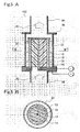
- Fig. 5A is a cross-sectional view obtained by cutting the water treatment device 10D along the flow of the flow path 54.
- Fig. 5B is a cross-sectional view taken along the line B-B' in Fig. 5A .
- the water treatment device 10D shown in the drawings has rod-shaped or cylindrical electrodes unlike the above-described other water treatment devices 10 and the like, but is the same as the water treatment devices 10 and the like in other aspects.
- a rod-shaped second electrode 14 is disposed in the central portion of the case 36.
- This rod-shaped second electrode 14 is surrounded by a spacer 18, a fiber electrode 16 and a first electrode 12, all of which have cylindrical shapes, and which are disposed in this sequence from the inner side.
- a negative potential is applied to the second electrode 14 from the outside, and a positive potential is applied to the first electrode 12 from the outside.
- a dashed line indicates a passage where the to-be-treated water 22 flows in the case 36.
- Fig. 5B shows that the second electrode 14 is formed into the rod shape, and that the spacer 18, the fiber electrode 16 and the first electrode 12 are formed into the cylindrical shapes.
- the to-be-treated water 22 supplied from the flow path 54 at the lower portion of the water treatment device 10D enters the inside of the case 36, and reaches a treatment chamber in the case 36 through the second electrode 14, the spacer 18, the fiber electrode 16 and the first electrode 12.
- the oxidant in the to-be-treated water 22 is removed.
- the treated water (to-be-treated water 22) is discharged outside the system from the case 36.
- the fiber electrode 16 is formed into the cylindrical shape, thus allowing the fiber electrode 16, having a relatively large area, to be accommodated in the small-sized case 36. Thereby, such a large area of the fiber electrode 16 increases the performance of decomposing the oxidant, thus promoting the reduction in size and the functional improvement of the water treatment device 10D.
- the water treatment device 10D has the cylindrical fiber electrode 16 in comparison with the structure described in the above Patent Document 1. Thereby, the area through which the to-be-treated water 22 passes is increased, and thus the treating efficiency of the entire device is improved.
- Fig. 6A is a plan view of the flat-film type water treatment device 10E, viewed from a filtration surface thereof, and Fig. 6B is a typical cross-sectional view thereof.
- the basic configuration of the water treatment device 10E shown in these drawings is the same as that of the above-described other water treatment device 10 and the like, and only configurations of the electrodes are different.
- the water treatment device 10E is configured to have a frame 62, having a frame shape made of a resin material or an anticorrosion metal (for example, stainless steel), which builds in a second electrode 14.
- the electrodes that constitute the water treatment device 10E are disposed inside the frame 62.
- the electrodes built in the device are electrically connected to connectors 64, 66 that are exposed to the outside.
- the connector 64 is connected to the built-in first electrode 12, and the connector 66 is connected to the second electrode 14.
- an opening portion is provided on top of the frame 62.
- the opening portion is formed of a pipe or the like that communicates with the internal space of the frame 62.
- the electrodes that constitute the water treatment device 10E are disposed so as to have film shapes (sheet or plate shapes) inside the frame 62.
- a single sheet of a second electrode 14 is disposed at the innermost portion of the frame 62.
- a space may be formed inside the frame 62 by the second electrode 14 that has, for example, a pouched shape, and the to-be-treated water 22 may be injected into the space.
- a spacer 18, a fiber electrode 16 and a first electrode 12 are formed in this sequence from the inner side so as to sandwich the second electrode 14 from both sides.
- the spacer 18, the fiber electrode 16 and the first electrode 12 may each have a pouched shape, or each two films of these constituents may be disposed so as to sandwich the second electrode 14 from both sides.
- the water treatment device 10E having the above-described configuration is used, for example, by injecting the to-be-treated water 22 into the device 10E through the opening portion provided on top of the frame. Specifically, the to-be-treated water 22 is injected into the frame 62 with pressurizing means such as a pump provided outside, and discharged outside the system by way of the second electrode 14, the spacer 18, the fiber electrode 16 and the first electrode 12. At this point, the water treatment device 10E may be used, while being accommodated inside storing means such as a tank. The function to remove an oxidant by the water treatment device 10E is the same as above.
- the positions of the electrodes and the spacer accommodated in the frame 62 may be switched to each other (that is, the positional relation between the outside constituent and the inside constituent may be altered).
- the to-be-treated water 22 enters the inside from the film-like electrode, and is discharged after being absorbed to the outside from the opening portion provided on top of the frame.
- the water treatment device 10E with the above configuration can be used, while being immersed in a reservoir tank for the to-be-treated water 22.
- the water treatment device 10E has a large water-permeable area (that is, the area of the fiber electrode 16) in comparison with the water treatment device described in Patent Document 1. Thus, the efficiency of treating the to-be-treated water 22 is improved.
- the multi-electrode type electrodes are used in the conventional technique while the single-electrode type electrodes are used in this embodiment.
- the multi-electrode type means a method in which an electrode that is not connected to a power supply (that is, in an electrically floating state) is interposed between a pair of electrodes that are connected to the power supply, thereby causing polarization.
- the multi-electrode type electrodes in the conventional technique require multiple layers of fiber electrodes. As a result, air in water to be treated remains in the fiber electrodes, thus reducing the treatment efficiency.
- the water treatment (that is, decomposition and reduction of the oxidant) is conducted with the single-electrode type electrodes.
- the water treatment device 10 is of the single-electrode type that includes the mesh-shaped first electrode 12, the fiber electrode 16 and the second electrode 14 that are electrically connected to the first electrode 12.
- the water treatment is conducted with the single layer of fiber electrode, and even when air is mixed in the to-be-treated water 22, the air does not remain in the fiber electrode 16, and is easily escaped therefrom.
- the decrease in the treatment efficiency, due to the air mixed in the to-be-treated water 22, is suppressed.
- the water treatment device of this embodiment is provided with the multiple water treatment devices in series with respect to the flow path as described with reference to Fig. 3 .
- the oxidant in the to-be-treated water 22 can be decomposed sufficiently by setting the multiple water treatment devices in series with respect to the flow path.
- a water treatment method is to remove an oxidant such as hypochlorous acid in water to be treated.
- a second water treatment method is to generate an oxidant at a second electrode 14 on a positive electrode side, and to decompose the generated oxidant with a fiber electrode 16.
- the water treatment device 10 is disposed to a flow path for to-be-treated water 22.
- the to-be-treated water 22 denotes, for example, tap water that contains an oxidant such as hypochlorous acid.
- the oxidant in this embodiment denotes a substance contributing to the sterilization of the to-be-treated water 22 by causing oxidation.
- examples of a microorganism include protozoa, bacteria, mold, yeast, parasites and viruses, or biologically active proteins and viruses.
- tap water that is discharged from the tip end of a water pipe contains free residual chlorine (oxidant) of at least 0.1 mg/L to sustain the sterilization effect in the flow path.
- the free residual chlorine is a collective term for chlorine, hypochlorous acid and hypochlorite ion.
- the amount of free residual chlorine in the tap water exceeds, for example, 1.0 mg/L or above, it causes problems where the taste of the tap water becomes poor, where the smell of the pool or public path becomes unpleasant, and so on. For this reason, in the first method, the oxidant in the to-be-treated water 22 such as tap water is removed.
- the specific configuration of the water treatment device 10 is the same as that described in the first embodiment.
- the second electrode 14, a spacer 18, a fiber electrode 16 and a first electrode 12 are disposed from the upstream side to the downstream side of the flow path for the to-be-treated water 22.
- the water treatment device 10 thus disposed is provided with a DC voltage.
- a power supply 20 applies a negative potential to the first electrode 12, and applies a positive potential to the second electrode 14.
- the fiber electrode 16 electrically connected to the first electrode 12 is negatively charged as the first electrode 12.
- the above decomposition is conducted with the fiber electrode 16 that is negatively charged by a negative potential applied from the power supply.
- the fiber electrode 16 is formed of extremely thin conductive fibers that are complexly and tightly packed.
- most of oxidants and water molecules that constitute the to-be-treated water 22 come into contact with any of the conductive fibers forming the fiber electrode 16, and then decomposed.
- An experiment has made clear that the performance of the fiber electrode 16 formed of the carbon fibers to decompose the oxidant does not rely on the thickness of the fiber electrode 16, but relies on the breadth of the area in a direction perpendicular to a flowing direction of the to-be-treated water 22.
- the aforementioned water treatment may be conducted, after multiple water treatment devices 10A and the like are set in series with respect to a flow path 54 as shown in Fig. 3 .
- the treatment performance of the water treatment devices is improved as a whole, and a larger amount of hypochlorous acid can be decomposed and removed.
- the water treatment devices 10A and the like remove all (or most) of hypochlorous acid contained in the to-be-treated water 22 which has a high concentration of hypochlorous acid, or whose flow amount is large. Consequently, the obtained treated water 22 does not contain hypochlorous acid at all (or contains little hypochlorous acid).
- hypochlorous acid in the water after the treatment it is possible to intentionally leave hypochlorous acid in the water after the treatment (to-be-treated water 22) so that the remained hypochlorous acid can be caused to have a sterilization function.
- the performance of the single water treatment device 10A to decompose hypochlorous acid is measured in an experience. Then, the concentration of hypochlorous acid in the to-be-treated water 22 as well as the flow amount of the to-be-treated water 22 are specified. On the basis of these measurements, a total amount of hypochlorous acid to be decomposed by the water treatment devices 10A and the like is made smaller than that contained in the to-be-treated water 22 that is to be treated.
- the water after the treatment contains a smaller amount of hypochlorous acid than that before the treatment.
- the to-be-treated water 22 whose chlorine smell is reduced, and which contains an appropriate amount of hypochlorous acid for sterilization can be obtained.
- the number of the water treatment devices 10A and the like disposed in the flow path 54 is determined on the basis of a target concentration value of the hypochlorous acid to be left in the water after the treatment (to-be-treated water 22).
- the number of the water treatment devices 10A and the like is determined on the basis of the amount of hypochlorous acid to be decomposed. More specifically, in a case where the concentration of the hypochlorous acid to be left in the water after the treatment (to be treated water 22) is lowered, it is necessary to decompose a large amount of hypochlorous acid. Thus, the multiple (for example, two or more) water treatment devices 10A and the like are set in series in the flow path 54. Meanwhile, in a case where a certain amount or larger (for example, 0.1 mg/L or above) of hypochlorous acid is to be left in the water after the treatment (to be treated water 22), the amount of hypochlorous acid to be decomposed is relatively small. Thus, a small number (for example, one) of the water treatment devices 10A and the like are set in the flow path 54.
- a flowmeter 58 and a valve 60 may be set in the flow path 54 at the preceding or following stage of the water treatment devices 10A and the like.
- the valve 60 is adjusted so that a predetermined flow amount can be measured with the flowmeter 58.
- the flow amount of the to-be-treated water 22 By restricting the flow amount of the to-be-treated water 22 with the valve 60, the flow amount of the to-be-treated water 22 that corresponds to the treatable amount of each of the water treatment devices 10A set in the flow path 54 can be achieved.
- the valve 60 by restricting, with the valve 60, the flow amount of the to-be-treated water 22 to less than the amount to be treated, all of hypochlorous acid contained in the to-be-treated water 22 before the treatment may be decomposed by the water treatment device 10A so that the water after the treatment (to-be-treated water 22) would not contain hypochlorous acid at all. Furthermore, by adjusting the valve 60 so that the flow amount of the to-be-treated water 22 would be greater than the treatable amount, only a fraction of hypochlorous acid contained in the to-be-treated water 22 before the treatment would be decomposed, and that hypochlorous acid of a certain amount or larger would be left in the water after the treatment (to-be-treated water 22).
- hypochlorous acid is described as an example of the oxidant
- the first method can also be employed for oxidants other than hypochlorous acid.
- any of hypohalous acid, ozone, hydrogen peroxide, hypochlorite ion and chlorine, or a combination of two or more of these is considered as the oxidant.
- the hydrogen peroxide solution is decomposed as in the following chemical reaction expressed by Formula 3.
- Formula 3 2H 2 O 2 + 4e - ⁇ O 2 + 2H 2 O
- the second electrode 14 on a positive-electrode side only needs to have a function as an electrode.
- the second electrode 14 may be formed of an anti-corrosion metal such as stainless steel. This point is in common with the first electrode 12.
- the main effect of this first method is to decompose the oxidant with the fiber electrode 16. Accordingly, the positional relationship between the first electrode 12 and the second electrode 14 may be altered.
- the second method does not simply remove the oxidant in the to-be-treated water 22 by the fiber electrode 16, but generate an oxidant with the water treatment device 10. Specifically, an oxidant is generated at the second electrode 14; the to-be-treated water 22 is sterilized between the second electrode 14 and the fiber electrode 16; and the oxidant contributed to the sterilization is decomposed by the fiber electrode 16.
- the surface of the second electrode 14 that is the positive electrode needs to be made of a substance capable of generating the oxidant.
- a substance capable of generating the oxidant examples include ruthenium (Ru), rhodium (Rh), palladium (Pd), tantalum (Ta), silver (Ag), osmium (Os), iridium (Ir), platinum (Pt) or gold (Au).
- Ru ruthenium
- Rh rhodium
- Pd palladium
- Ta tantalum
- silver Ag
- Ir iridium
- platinum platinum
- Au gold
- the first electrode 12 should be made of a conductive material having an excellent anti-corrosion property, since the first electrode 12 serves as conductive means for the fiber electrode 16.
- the second method is basically the same as the above-described first method, but the difference from the first method is a chemical reaction that takes place at the second electrode.
- the to-be-treated water 22 needs to contain a substance that can be the oxidant. More specifically, when hypochlorous acid is generated as the oxidant at the second electrode 14, the water to be treated before the treatment needs to contain chlorine (chloride ion).
- hypochlorous acid is generated as the oxidant at the second electrode 14
- hypochlorous acid is generated as the oxidant at the second electrode 14
- the water to be treated before the treatment needs to contain chlorine (chloride ion).
- ozone or a hydrogen peroxide solution is employed as the oxidant to be generated, water serves as a part of the oxidant.
- a process of the second method is specifically described, taking hypochlorous acid as an example. Firstly, when the to-be-treated water 22 containing a chloride ion comes into contact with the second electrode 14, reactions expressed by the following Formulae 4 and 5 take place. Then, hypochlorous acid is generated.
- Formula 4 2Cl - ⁇ Cl 2 + 2e -
- Formula 5 Cl 2 + H 2 O ⁇ HClO + HCl
- the generated hypochlorous acid sterilizes microorganisms in the to-be-treated water 22 between the second electrode 14 and the fiber electrode 16 (that is, an area where the spacer 18 is disposed). Thereby, all (or most) of the microorganisms in the to-be-treated water 22 are removed.
- the microorganisms in the water to be treated 22 may include, in some cases, protozoa which are so small that it is difficult to sterilize them with hypochlorous acid and the like.
- the microorganisms in the water to be treated 22 may include, in some cases, protozoa which are so small that it is difficult to sterilize them with hypochlorous acid and the like.
- by applying a positive potential with a high voltage to the second electrode 14 to generate high-concentration hypochlorous acid it is possible to sterilize and eliminate even the small protozoa.
- hypochlorous acid generated at the second electrode 14 is converted into a chloride ion and water.
- the fiber electrode 16 is formed of extremely thin conductive fibers that are complexly woven, the microorganisms thus sterilized are trapped by the fiber electrode 16.
- the hypochlorous acid thus generated can also be used to sterilize microorganisms trapped by the fiber electrode 16, and the voltage can also be applied to them.
- the microorganisms included in the water (to-be-treated water 22) treated with the water treatment device 10 are sterilized, and removed therefrom.
- the sterilized water (to-be-treated water 22) as described above passes through the water-permeable first electrode 12, and is discharged outside the system.
- the generation of and the sterilization with hypochlorous acid are conducted in the device 10, and the generated hypochlorous acid is removed therein.
- the amount of hypochlorous acid in the water to be treated after the treatment is equal to or less than the amount of hypochlorous acid in the water to be treated 22 before the treatment.
- the worsening of the chlorine smell due to the water treatment with the water treatment device 10 does not occur.
- ozone or a hydrogen peroxide solution can be employed as the oxidant.
- water serves as a material of the oxidant.
- the ozone when ozone is employed as the oxidant, the ozone is generated at the second electrode 14 by any one of the following reaction formulae expressed by Formulae 7 and 8.
- Formula 7 3H 2 O ⁇ 6H + + 6e - + O 3
- Formula 8 H 2 O + O 2 ⁇ 2H + + 2e - + O 3
- the free residual chlorine includes chlorine, hypochlorous acid and a hypochlorite ion.
- a fiber electrode 16 is a carbon fiber electrode formed of carbon fibers.
- the diameter of the fiber electrode 16 is 40 mm (the area is approximately 1256 mm 2 ), and the thickness thereof is 14 mm.
- the fiber electrode 16 is compressed to have a thickness of approximately 10 mm.
- mesh-shaped titanium with its surface covered with platinum was used as a first electrode 12 and a second electrode 14.
- a spacer 18 employed is a filled-up PP resin (non-conductive material). The distance between the lower end of the fiber electrode 16 and the second electrode 14 is 10 mm.
- the longitudinal axis indicates a free residual chlorine concentration (mg/L) of the water (to-be-treated water) after the treatment
- the lateral axis indicates a value of a current that passes between the two electrodes applied with the voltages.
- a larger current value suggests a higher voltage value thus applied.
- a solid line with rhombus shaped points indicates a result that water to be treated with a flow rate of 400 mL/min passes through the water treatment device 10 of this embodiment having the above-described configuration.
- a solid line with square shaped points indicates a result that the water to be treated with a flow rate of 800 mL/min passes through the water treatment device 10 of this embodiment having the similar configuration as above.
- a solid line with triangle shaped points indicates a result that the water to be treated with a flow rate of 400 mL/min passes through the conventional water treatment device described in Patent Document 1.
- the difference between the conventional water treatment device and the water treatment device of this embodiment is the polarity of the electrode connected to the fiber electrode. Specifically, in the conventional water treatment device, a positive potential is applied to the fiber electrode (carbon fiber).
- the water treatment device of this embodiment 400 mL/min
- the current value is 10 mA
- the residual chlorine concentration is approximately 0.2 mg/L.
- the free residual chlorine concentration is 0 mg/L.
- the water treatment device of this embodiment 800 mL/min
- the residual chlorine concentration is decreased as the current value is increased.
- a part of hypochlorous acid is decomposed by the water treatment device 10, and the rest of hypochlorous acid remains without being removed.
- the current value is 30 mA
- the free residual chlorine concentration is 0 mg/L.
- the free residual chlorine having a concentration of approximately 1.8 mg/L is contained in the water (to-be-treated water) after the treatment.
- the residual chlorine concentration is decreased only slightly as the current value is increased. This is because, in the conventional water treatment device, the carbon fiber is connected to the positive electrode, so that hypochlorous acid is not decomposed by the carbon fiber.
- the flow rate of the water to be treated is decreased with regulating means such as a valve.
- regulating means such as a valve.
- the flow rate of the water to be treated is approximately 400 mL/min when the value of the current that passes through the electrodes is 30 mA.
- the treated water thus obtained does not contain the free residual chlorine at all (or hardly contains the free residual chlorine).
- the flow rate of the water to be treated is increased by adjusting the valve.
- the flow amount of the water to be treated is approximately 800 mL/min when the value of the current that passes through the electrodes is 30 mA.
- approximately 0.19 mg/L of the free residual chlorine is left in the water (to-be-treated water) after the treatment, and the treated water thus obtained has a sterilization function owing to the remaining free residual chlorine.
- the concentration of the residual chlorine in the water (to-be-treated water) after the treatment can be adjusted by altering: the value of the current that passes through the electrodes; the number of the water treatment devices to be disposed; or the area of the fiber electrode.
- Fig. 8 is a graph showing an experimental result to verify the effect of the second water treatment method described above. In other words, this experiment was conducted to demonstrate hypochlorous acid (oxidant) generated at the second electrode 14 in the water treatment device 10 shown in Fig. 1 .
- the lateral axis of this graph indicates a value of a current (mA) that passes between the two electrodes, and the longitudinal axis indicates a residual chlorine concentration (mg/L).
- the water treatment device used has a configuration of the water treatment device 10 shown in Fig. 1 but the fiber electrode 16 is removed therefrom.
- the reason why the fiber electrode 16 is removed is that, if the experiment is conducted with the fiber electrode 16, hypochlorous acid generated at the second electrode 14 is decomposed by the fiber electrode 16, so that the amount of hypochlorous acid generated at the second electrode 14 cannot be specified.
- a method for this experiment is basically the same as that described with reference to Fig. 7 .
- the water to be treated containing chlorine (chloride ion) is introduced into the water treatment device through which electricity has been conducted. Then, the concentration of the residual chlorine in the water (to-be-treated water) treated with the water treatment device is measured.
- the concentration of the residual chlorine in the water (to-be-treated water) after the treatment is increased as the current value is increased.
- the amount of hypochlorous acid (oxidant) to be generated can be altered by adjusting the value of the current (in other words, voltage value) that passes through the two electrodes.
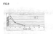
- Fig. 9 is a graph showing an experimental result obtained to clarify a correlation between the treatment efficiency and the thickness of the fiber electrode 16 (for example, an electrode made of a carbon fiber) shown in Fig. 1 .
- the lateral axis of this graph indicates a value of a current that passes through the two electrodes, and the longitudinal axis indicates a concentration of free residual chlorine in the water (to-be-treated water) after the treatment.
- a water treatment device and an experimental method used in this experiment are the same as those described with reference to Fig. 7 . This experiment was conducted with the two fiber electrodes 16 having different thicknesses from each other.
- the experiment was conducted on the water treatment device provided with the fiber electrode 16 having a thickness of 10 mm (solid line with rhombus shaped points), and on the water treatment device provided with the fiber electrode 16 having a thickness of 1 mm (solid line with square shaped points), as shown in Fig. 1 .
- hypochlorous acid residual chlorine
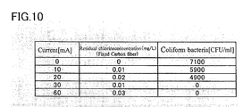
- the concentration of hypochlorous acid (residual chlorine) in the water (to-be-treated water) after the treatment does not change largely, although the current value is increased. Specifically, as the current value is increased, hypochlorous acid is also detected (when the current value is 30 mA, the residual chlorine concentration is 0.01 mg/L, for example). However, the value of this hypochlorous acid is very small as compared with the concentration of hypochlorous acid contained in tap water. This is because the fiber electrode 16 decomposes most of the hypochlorous acid generated at the second electrode 14 as shown in Fig. 1 . When the value of the current applied to the electrodes is increased, a larger amount of hypochlorous acid is generated at the second electrode 14.
- the decomposition effect of the fiber electrode 16 is also increased.
- the amount of hypochlorous acid contained in the water (to-be-treated water 22) after the treatment is hardly increased, while the sterilization effect is increased.
- the increase in the current value decreases the number of the coliform bacteria in the water (to-be-treated water) after the treatment. Specifically, when the current value is 30 mA or above, the number of the coliform bacteria in the treated water is 0 CFU/mL.
- the water treatment device 10 of this embodiment generates an oxidant (for example, hypochlorous acid) at the second electrode 14, and decomposes the generated oxidant with the fiber electrode 16 (first electrode 12). In this manner, the device 10 sterilizes the water to be treated between the two electrodes with the thus generated oxidant.
- the water treatment method sterilization method which causes the water (to-be-treated water) after the treatment not to contain the oxidant, is implemented.
- other oxidants such as ozone and a hydrogen peroxide solution.
- an oxidant such as hypochlorous acid can be removed from water to be treated, thus suppressing the deterioration in taste due to chlorine smell and the corrosion of a metallic component such as a faucet.
- hypochlorous acid having a high sterilizing effect exists in the flowing water to be treated between the two electrodes, and thus the sterilization is conducted. Furthermore, the hypochlorous acid contributed to the sterilization is decomposed at the fiber electrode that is connected to the first electrode on the downstream side.
- the generation of the oxidant, the sterilization with the oxidant thus generated, and the decomposition of the oxidant are conducted inside the water treatment device. Thereby, the increase in the oxidant amount included in the treated water is suppressed, and accordingly the treated water is sterilized.
Landscapes
- Chemical & Material Sciences (AREA)
- Chemical Kinetics & Catalysis (AREA)
- Electrochemistry (AREA)
- General Chemical & Material Sciences (AREA)
- Life Sciences & Earth Sciences (AREA)
- Hydrology & Water Resources (AREA)
- Engineering & Computer Science (AREA)
- Environmental & Geological Engineering (AREA)
- Water Supply & Treatment (AREA)
- Organic Chemistry (AREA)
- Water Treatment By Electricity Or Magnetism (AREA)
Applications Claiming Priority (1)
| Application Number | Priority Date | Filing Date | Title |
|---|---|---|---|
| JP2007186074A JP4785800B2 (ja) | 2007-07-17 | 2007-07-17 | 水処理装置 |
Publications (1)
| Publication Number | Publication Date |
|---|---|
| EP2017229A1 true EP2017229A1 (de) | 2009-01-21 |
Family
ID=39764765
Family Applications (1)
| Application Number | Title | Priority Date | Filing Date |
|---|---|---|---|
| EP08012963A Withdrawn EP2017229A1 (de) | 2007-07-17 | 2008-07-17 | Wasserbehandlungsvorrichtung und Wasserbehandlungsverfahren |
Country Status (5)
| Country | Link |
|---|---|
| US (1) | US20090026088A1 (de) |
| EP (1) | EP2017229A1 (de) |
| JP (1) | JP4785800B2 (de) |
| KR (1) | KR20090008143A (de) |
| CN (1) | CN101348291A (de) |
Cited By (1)
| Publication number | Priority date | Publication date | Assignee | Title |
|---|---|---|---|---|
| WO2011135749A1 (en) * | 2010-04-30 | 2011-11-03 | Aquaecos Ltd. | Membrane-electrode assembly, electrolytic cell using the same, method and apparatus for producing ozone water, method for disinfection and method for wastewater or waste fluid treatment |
Families Citing this family (14)
| Publication number | Priority date | Publication date | Assignee | Title |
|---|---|---|---|---|
| KR20100036495A (ko) * | 2008-09-30 | 2010-04-08 | 삼성전자주식회사 | 탈 이온화장치 및 이에 사용되는 전극 모듈 및 그 제조방법 |
| RU2534125C2 (ru) * | 2009-06-29 | 2014-11-27 | Протергоу Инк. | Способ электрохимической обработки сточных вод и устройство для его осуществления |
| TWI405725B (zh) * | 2009-08-21 | 2013-08-21 | Univ Nat Cheng Kung | 透水性電化學微生物反應牆及其使用方法 |
| JPWO2011065013A1 (ja) * | 2009-11-27 | 2013-04-11 | 有限会社ターナープロセス | pH調整装置 |
| TWI362366B (en) * | 2009-12-15 | 2012-04-21 | Ind Tech Res Inst | Fluid self-electricity-generation and electroreduction module |
| US8679351B2 (en) * | 2009-12-30 | 2014-03-25 | Hydrover Holding S.A. | Process and apparatus for decontaminating water by producing hydroxyl ions through hydrolysis of water molecules |
| JP5113892B2 (ja) * | 2010-04-30 | 2013-01-09 | アクアエコス株式会社 | 膜−電極接合体、これを用いる電解セル、オゾン水製造装置、オゾン水製造方法、殺菌方法及び廃水・廃液処理方法 |
| KR101020925B1 (ko) * | 2010-05-17 | 2011-03-09 | 주식회사 이온팜스 | 이온수 제조장치 |
| KR101220891B1 (ko) * | 2010-06-30 | 2013-01-11 | 문상봉 | 3차원 다공성 복극 전극 및 이를 구비한 전기살균 필터와 이를 이용한 수처리 방법 |
| JP5873085B2 (ja) * | 2010-07-21 | 2016-03-01 | カンブリアン イノベーション エルエルシー | 廃水を処理するための生物−電気化学的システムおよび酸性ガスを処理するための方法 |
| CN102219299B (zh) * | 2011-04-01 | 2012-12-19 | 中国科学院成都生物研究所 | 一种废水厌氧氧化与负氧离子偶联发生装置及方法 |
| JP2013061141A (ja) * | 2011-09-15 | 2013-04-04 | Daikin Industries Ltd | ヒートポンプ給湯機 |
| JP5812141B2 (ja) * | 2014-03-28 | 2015-11-11 | ダイキン工業株式会社 | 液中放電装置 |
| KR102355824B1 (ko) * | 2018-12-27 | 2022-01-26 | 코웨이 주식회사 | 팔라듐, 이리듐 및 탄탈럼으로 구성된 전극용 촉매층 및 상기 전극용 촉매가 코팅된 살균수 생성 모듈 |
Citations (5)
| Publication number | Priority date | Publication date | Assignee | Title |
|---|---|---|---|---|
| US4445990A (en) * | 1981-11-12 | 1984-05-01 | General Electric Company | Electrolytic reactor for cleaning wastewater |
| US5256268A (en) * | 1990-07-18 | 1993-10-26 | Konica Corporation | Water treatment method and apparatus |
| WO2004079840A2 (en) * | 2003-02-28 | 2004-09-16 | Evat, Inc. | Three-dimensional flow-through electrode and electrochemical cell |
| JP2005254118A (ja) | 2004-03-11 | 2005-09-22 | Sanyo Electric Co Ltd | 微生物収集装置及び微生物収集方法 |
| JP2007186074A (ja) | 2006-01-13 | 2007-07-26 | Marui:Kk | サドルクランプ |
Family Cites Families (8)
| Publication number | Priority date | Publication date | Assignee | Title |
|---|---|---|---|---|
| US5106463A (en) * | 1988-08-15 | 1992-04-21 | The Electrosynthesis Company, Inc. | High yield methods for electrochemical preparation of cysteine and analogues |
| JP3014427B2 (ja) * | 1990-09-26 | 2000-02-28 | コニカ株式会社 | 被処理水の処理方法 |
| US5532083A (en) * | 1994-07-26 | 1996-07-02 | Mccullough; Francis P. | Flexible carbon fiber electrode with low modulus and high electrical conductivity, battery employing the carbon fiber electrode, and method of manufacture |
| US6342150B1 (en) * | 1998-09-09 | 2002-01-29 | Thomas Clay Sale | Redox water treatment system |
| JP2003136067A (ja) * | 2001-10-31 | 2003-05-13 | Sanyo Electric Co Ltd | 水処理方法及び水処理システム |
| JP2006334212A (ja) * | 2005-06-03 | 2006-12-14 | Sanyo Electric Co Ltd | 除菌装置及び空気調和装置 |
| EP1995220B1 (de) * | 2007-05-14 | 2011-08-03 | Sanyo Electric Co., Ltd. | Wasserbehandlungsvorrichtung |
| EP2168921A1 (de) * | 2008-09-30 | 2010-03-31 | Sanyo Electric Co., Ltd. | Wasserbehandlungsvorrichtung |
-
2007
- 2007-07-17 JP JP2007186074A patent/JP4785800B2/ja not_active Expired - Fee Related
-
2008
- 2008-07-16 US US12/173,931 patent/US20090026088A1/en not_active Abandoned
- 2008-07-16 KR KR1020080068876A patent/KR20090008143A/ko not_active Ceased
- 2008-07-17 CN CNA2008101338255A patent/CN101348291A/zh active Pending
- 2008-07-17 EP EP08012963A patent/EP2017229A1/de not_active Withdrawn
Patent Citations (5)
| Publication number | Priority date | Publication date | Assignee | Title |
|---|---|---|---|---|
| US4445990A (en) * | 1981-11-12 | 1984-05-01 | General Electric Company | Electrolytic reactor for cleaning wastewater |
| US5256268A (en) * | 1990-07-18 | 1993-10-26 | Konica Corporation | Water treatment method and apparatus |
| WO2004079840A2 (en) * | 2003-02-28 | 2004-09-16 | Evat, Inc. | Three-dimensional flow-through electrode and electrochemical cell |
| JP2005254118A (ja) | 2004-03-11 | 2005-09-22 | Sanyo Electric Co Ltd | 微生物収集装置及び微生物収集方法 |
| JP2007186074A (ja) | 2006-01-13 | 2007-07-26 | Marui:Kk | サドルクランプ |
Cited By (1)
| Publication number | Priority date | Publication date | Assignee | Title |
|---|---|---|---|---|
| WO2011135749A1 (en) * | 2010-04-30 | 2011-11-03 | Aquaecos Ltd. | Membrane-electrode assembly, electrolytic cell using the same, method and apparatus for producing ozone water, method for disinfection and method for wastewater or waste fluid treatment |
Also Published As
| Publication number | Publication date |
|---|---|
| JP4785800B2 (ja) | 2011-10-05 |
| KR20090008143A (ko) | 2009-01-21 |
| JP2009022838A (ja) | 2009-02-05 |
| CN101348291A (zh) | 2009-01-21 |
| US20090026088A1 (en) | 2009-01-29 |
Similar Documents
| Publication | Publication Date | Title |
|---|---|---|
| EP2017229A1 (de) | Wasserbehandlungsvorrichtung und Wasserbehandlungsverfahren | |
| US6773575B2 (en) | Electrolytic cell and process for the production of hydrogen peroxide solution and hypochlorous acid | |
| JP4392354B2 (ja) | 高電界電解セル | |
| US8062485B2 (en) | Water treatment device | |
| US9963362B2 (en) | Method for electrochemical bromide and/or chloride removal | |
| JP2008307524A (ja) | 水処理装置 | |
| CN108217862B (zh) | 一种双电极电絮凝-电催化臭氧装置及工业废水处理方法 | |
| WO2015154707A1 (zh) | 健康饮水机 | |
| KR102211119B1 (ko) | Cdi 방식의 수처리 장치 | |
| CN115087623A (zh) | 水处理电化学反应器 | |
| WO2015154705A1 (zh) | 商务水机 | |
| JP6847477B1 (ja) | 電解水製造装置及びこれを用いる電解水の製造方法 | |
| JP2008279408A (ja) | 水処理装置及び水処理システム | |
| JP3056511B2 (ja) | 被処理水の処理装置 | |
| CN205241298U (zh) | 低功耗富氢水电解商务水机 | |
| JP4249658B2 (ja) | 電解水生成装置 | |
| JP3014427B2 (ja) | 被処理水の処理方法 | |
| WO2008062507A1 (en) | Electrolytic hydrogen water production system | |
| JP2007105691A (ja) | 水の改質器 | |
| JPH05309362A (ja) | 被処理水の処理方法及び被処理水処理用複極式電解槽 | |
| JPH04219192A (ja) | 被処理水の処理方法 | |
| JPH04114785A (ja) | 被処理水の処理方法 | |
| JPH05200387A (ja) | 被処理水の処理方法及び装置 | |
| JP5285393B2 (ja) | 電解装置 | |
| WO2022195708A1 (ja) | 電解水製造装置及びこれを用いる電解水の製造方法 |
Legal Events
| Date | Code | Title | Description |
|---|---|---|---|
| PUAI | Public reference made under article 153(3) epc to a published international application that has entered the european phase |
Free format text: ORIGINAL CODE: 0009012 |
|
| AK | Designated contracting states |
Kind code of ref document: A1 Designated state(s): AT BE BG CH CY CZ DE DK EE ES FI FR GB GR HR HU IE IS IT LI LT LU LV MC MT NL NO PL PT RO SE SI SK TR |
|
| AX | Request for extension of the european patent |
Extension state: AL BA MK RS |
|
| RIN1 | Information on inventor provided before grant (corrected) |
Inventor name: OE, HANA Inventor name: OGAWA, YUI Inventor name: KUWAI, YASUYUKI Inventor name: UMEZAWA, HIROYUKI Inventor name: SUMIDA, YASUTERU |
|
| 17P | Request for examination filed |
Effective date: 20090721 |
|
| AKX | Designation fees paid |
Designated state(s): DE GB IT |
|
| 17Q | First examination report despatched |
Effective date: 20090916 |
|
| STAA | Information on the status of an ep patent application or granted ep patent |
Free format text: STATUS: THE APPLICATION IS DEEMED TO BE WITHDRAWN |
|
| 18D | Application deemed to be withdrawn |
Effective date: 20110830 |