EP2017379A1 - Montage de traverses dans un métier à tisser - Google Patents
Montage de traverses dans un métier à tisser Download PDFInfo
- Publication number
- EP2017379A1 EP2017379A1 EP08160235A EP08160235A EP2017379A1 EP 2017379 A1 EP2017379 A1 EP 2017379A1 EP 08160235 A EP08160235 A EP 08160235A EP 08160235 A EP08160235 A EP 08160235A EP 2017379 A1 EP2017379 A1 EP 2017379A1
- Authority
- EP
- European Patent Office
- Prior art keywords
- cross beam
- weaving machine
- machine according
- deformations
- lateral
- Prior art date
- Legal status (The legal status is an assumption and is not a legal conclusion. Google has not performed a legal analysis and makes no representation as to the accuracy of the status listed.)
- Granted
Links
Images



Classifications
-
- D—TEXTILES; PAPER
- D03—WEAVING
- D03D—WOVEN FABRICS; METHODS OF WEAVING; LOOMS
- D03D39/00—Pile-fabric looms
- D03D39/16—Double-plush looms, i.e. for weaving two pile fabrics face-to-face
- D03D39/18—Separating the two plush layers, e.g. by cutting
-
- D—TEXTILES; PAPER
- D03—WEAVING
- D03D—WOVEN FABRICS; METHODS OF WEAVING; LOOMS
- D03D49/00—Details or constructional features not specially adapted for looms of a particular type
- D03D49/02—Construction of loom framework
Definitions
- the present invention relates to a weaving machine comprising at least one cross beam which is carried and/or supported by at least two lateral frames of the weaving machine, in which the relative movement of the cross beam with respect to the lateral frames has at least one degree of freedom as a result of deformations of the lateral frames.
- a weaving machine is usually composed of two lateral frames on either side of the weaving machine which are connected to one another via a number of intermediate or mounted cross beams. These measures are required in order to give the weaving machine the required strength in order to be able to absorb the forces generated during normal operation of the machine.
- a significant number of these cross beams also directly or indirectly have a function in the weaving process, such as, for example: yam guide roller, fabric guide roller, harness board support (also called cumber board support), selvedge system support and, with face-to-face weaving machines, in particular upper rod, lower rod and cutting bench.
- the structure composed of the lateral frames and the cross beams is subjected to a cyclic load of great forces due to the moving parts.
- the various cross beams which do not perform a functional rotating or oscillating movement, are connected in a clamping manner by means of bolt connections to the (two or more) lateral frames which are each in turn connected to a support structure or to the ground.
- the cyclic load leads to vibrations which continue on the lateral frames and in this way pass to the various cross beams which are connected to the lateral frames.
- the cross beam has a function or is a support for a functional unit, the resulting vibrations on the cross beams adversely affect the quality of the woven product, the stability of the weaving process by an increased number of standstills or the service life of the components of the weaving machine.
- the two fabrics are kept a distance apart which distance is determined by the opening between the lower cutting rod and upper cutting rod, provided the tension on the warp threads is sufficiently high.
- the sandwich fabric is presented to the cutting device.
- the cutting device consists of a knife carriage with a cutting knife which moves to and fro across the cutting bench across the width of the fabric.
- the cutting bench is fitted in the weaving machine as a cross beam and connected to the lateral frames.
- a pulling roller pulls the fabric formed out of the fabric-forming zone in order to roll it up as a cloth.
- tensile forces are exerted which, for each pulling roller, may be as high as 15 kN/m.
- the accommodating beam for the harness boards for guiding the harness cords in a jacquard weaving machine can vibrate and deform, as a result of which the contact between the harness cords and the harness board becomes more intense, resulting in increased wear.
- the cross beam which supports one or more selvedge shed formation systems may be caused to vibrate and deform, as a result of which the selvedge results in reduced dimensional stability and the selvedge shed formation system having a reduced service life.
- European patent EP 1 614 784 discloses a method for also supporting the cutting bench between the supporting surfaces on the lateral frames by connecting these to a guiding support at one or more intermediate locations. This method is effective at reducing the vibrations, but at relatively high speeds the resulting vibrations remain too high, thus adversely affecting the quality of the cut fabric.
- the object of the invention is achieved by providing a weaving machine comprising at least one cross beam which is carried and/or supported by at least two lateral frames of the weaving machine, in which the relative movement of the cross beam with respect to the lateral frames has at least one degree of freedom as a result of deformations of the lateral frames, and in which at least one lateral frame of the weaving machine comprises at least one attachment element which is hingedly connected to the cross beam and is designed to carry and/or support the cross beam, as a result of which the deformations of the cross beam are smaller than the deformations of the lateral frame on the connection surface with the cross beam.
- This allows deformation of the lateral frame without the cross beam having to follow the entire deformation of the lateral frame at the connection to the cross beam.
- the cross beam of the weaving machine according to the present invention will deform and vibrate to a lesser degree than in known weaving machines.
- the cross beam is hingedly connected to the attachment element by means of a hinge pin. More particularly, the hinge pin extends along a main axis of inertia of the cross beam, as a result of which the hinge pin lies along the neutral deformation line of the cross beam so that the deformations which are passed on are minimized.
- the hinge pin in a preferred embodiment, comprises a connecting element which is connected to a lateral frame of the weaving machine by means of an attenuating device.
- Said attenuating device comprises, in particular, a spring, a pneumatic cylinder or a hydraulic cylinder.
- the cross beam in the weaving machine is freely rotatable in the attachment element.
- the cross beam comprises a spherical element
- the attachment element is of a socket-shaped design, as a result of which the spherical element is freely rotatable in the socket-shaped attachment element.
- the radius of the socket-shaped attachment element is greater than the radius of the spherical element.
- the cross beam is a cutting bench in a face-to-face weaving machine.
- the cross beam is an upper or lower rod in a face-to-face weaving machine.
- the cross beam is a support for selvedge systems in a weaving machine.
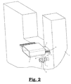
- a weaving machine is composed of two lateral frames (1) on either side of the weaving machine which are connected to one another by means of a number of intermediate or mounted cross beams (2).
- forces are generated during normal operation of the weaving machine which may cause deformations of the lateral frames (1) which may be passed onto the cross beams (2) with all the adverse consequences this entails.
- At least one lateral frame (1) comprises at least one attachment element (3, 10, 17) which is provided in order to carry and/or support the cross beam (2).
- the cross beam (2) of the weaving machine as illustrated in Figs. 1 comprises a first projection (5), in which, between the attachment element (3) and the first projection (5), an attenuating material (4), such as for example rubber, felt or cork is provided.
- the attenuating material (4) absorbs part of the deformations of the lateral frames (1) without passing these deformations on to the cross beam (2).
- connection surface between the lateral frame (1) and the cross beam is at the attachment element (3).
- the attachment element is designed as a mounting surface (3) on which the cross beam (2) with its first projection (5) is mounted.
- the attenuating material (4) is provided in the space between the mounting surface (3) and the first projection (5).
- the mounting surface (3) preferably extends horizontally and is in particular at the neutral fibre of the cross beam (2), as a result of which, in this mounting surface (3), the deformation of the cross beam (2) as a result of the deformations on the lateral frame (1) only consists of a tilting of the first projection (5) of the cross beam (2) without a lengthening or shortening of the cross beam (2) occurring.
- neutral fibre is understood to mean the line in which no lengthening or shortening of the cross beam occurs upon bending of the cross beam.
- the attenuating material (4) only has to attenuate the tilting of the first projection (5) of the cross beam (2), thus significantly limiting the resulting deformation of the cross beam (2) or almost reducing it to zero.
- the attachment element (3) may, however, equally well be a vertical surface of a lateral frame which is subsequently connected to a vertical first projection of the cross beam by means of a bolt connection.
- the attenuating material (4) may be inserted between the vertical surface and the vertical first projection.
- the cross beam (2) comprises a second projection (6) which is mounted in an attenuating manner at a lateral frame (1) of the weaving machine.
- the second projection (6) can be in the form of a surface and extend between two surfaces (8) which are connected to the lateral frames (1). These surfaces (8) between which the second projection (6) of the cross beam (2) extends are covered with an attenuating material (8) on their contact surface with the second projection (6).
- the attenuating material (8) may, for example, be rubber, felt or cork.
- the second projection (6) can extend in any suitable direction (downwards, upwards, forwards, backwards, or in another direction).
- Said second projection (6) may also be in the form of an axle which extends through a sleeve which is connected to the lateral frame (1) (not illustrated in the figures). This sleeve is preferably covered with an attenuating material on the inside.
- the cross beam (2) is hingedly connected to an attachment element (10).
- the cross beam (2) is hingedly connected to the attachment element (10) via a hinge pin (9).
- the hinge pin (9) is mounted in the attachment element (10).
- the cross beam (2) is the cutting bench (2) of a face-to-face weaving machine and the hinge pin (9) is connected to a lateral flange (15) of the cutting bench (2) in the centre or at its two ends, while the lateral frame (1) is provided, on its attachment element (10), with two carrier elements (16) having a cover (not illustrated) and in which the axle (9) can be clamped in a mounted manner, the lateral frame (1) will be able to deform without the deformation being completely passed on to the cutting bench (2) after the carrier elements (16) having a cover have been fitted around the hinge pin (9).
- the lateral frame can hingedly rotate in the attachment element (10) with its carrier elements (16) around the hinge pin (9) which is connected to the cutting bench (2), as a result of which this rotating movement is not passed on to the cutting bench (2) so that the cutting bench (2) is subjected to fewer vibrations.
- the same effect can be achieved with other cross beams (2) in face-to-face weaving machines or flat weaving machines.
- the hinge pin (9) is oriented along a main axis of inertia (11) of the cross beam (2).
- the axle (9) lies along the neutral deformation line of the cross beam (2) and the deformations which are passed on are additionally minimized.
- the lateral frame (1) can rotate in the direction of rotation (12) in a clockwise or counterclockwise manner.
- a connecting element (13) in the form of a lever may be attached to the hinge pin (9), which connecting element (13) extends radially with respect to the axle (9) and the end of which is connected to an attenuating device (14), in order to attenuate the rotations (12) of the hinge pin (9).
- the attenuating device (14) may, for example, be a spring or a pneumatic or hydraulic cylinder or an attenuating material.
- the cross beam (2) is provided so as to be freely rotatable in the attachment element (17).
- the cross beam (2) comprises a spherical element and the attachment element (17) is of a socket-shaped design, as a result of which the spherical element is freely rotatable in the socket-shaped attachment element (17).
- a ball-and-socket joint (17) is formed, as it were.
- the cross beam (2) is mounted in an attenuating manner in a least one point (18). If, relative to the ball-and-socket joint (17), this mounting point/mounting surface (18) is on that side on which the centre of gravity of the cross beam (2) is situated, one such mounting point/mounting surface (18) is sufficient.
Landscapes
- Engineering & Computer Science (AREA)
- Textile Engineering (AREA)
- Looms (AREA)
- Vibration Dampers (AREA)
Applications Claiming Priority (1)
| Application Number | Priority Date | Filing Date | Title |
|---|---|---|---|
| BE2007/0352A BE1017696A3 (nl) | 2007-07-16 | 2007-07-16 | Ophanging van dwarsliggers in een weefmachine. |
Publications (2)
| Publication Number | Publication Date |
|---|---|
| EP2017379A1 true EP2017379A1 (fr) | 2009-01-21 |
| EP2017379B1 EP2017379B1 (fr) | 2010-06-30 |
Family
ID=39262741
Family Applications (1)
| Application Number | Title | Priority Date | Filing Date |
|---|---|---|---|
| EP08160235A Active EP2017379B1 (fr) | 2007-07-16 | 2008-07-11 | Montage de traverses dans un métier à tisser |
Country Status (4)
| Country | Link |
|---|---|
| EP (1) | EP2017379B1 (fr) |
| AT (1) | ATE472621T1 (fr) |
| BE (1) | BE1017696A3 (fr) |
| DE (1) | DE602008001632D1 (fr) |
Citations (6)
| Publication number | Priority date | Publication date | Assignee | Title |
|---|---|---|---|---|
| DE3344440A1 (de) * | 1982-12-09 | 1984-07-05 | ZVS - Výzkumněvývojový ústav, koncernová účelová organizace, Brno | Tragelement, insbesondere fuer die rahmen von textilmaschinen |
| US4478255A (en) * | 1982-05-26 | 1984-10-23 | Societe Alsacienne De Construction De Materiel Textile | Devices for cutting pile threads in a loom for weaving velvet in a double layer |
| DE19534143A1 (de) * | 1994-09-14 | 1996-03-21 | Wiele Michel Van De Nv | Schneideeinrichtung für eine Doppelstück-Webmaschine |
| US5799706A (en) * | 1995-01-26 | 1998-09-01 | Icbt Diederichs | Weaving loom with vibration damper |
| WO2004092465A1 (fr) * | 2003-04-17 | 2004-10-28 | Picanol N.V. | Entrainement pour des cadres de lisses d'un metier a tisser |
| EP1614784A1 (fr) | 2004-07-05 | 2006-01-11 | NV Michel van de Wiele | Système de support d'un dispositif de coupe dans un métier à tisser double pièce |
-
2007
- 2007-07-16 BE BE2007/0352A patent/BE1017696A3/nl not_active IP Right Cessation
-
2008
- 2008-07-11 AT AT08160235T patent/ATE472621T1/de not_active IP Right Cessation
- 2008-07-11 EP EP08160235A patent/EP2017379B1/fr active Active
- 2008-07-11 DE DE602008001632T patent/DE602008001632D1/de active Active
Patent Citations (6)
| Publication number | Priority date | Publication date | Assignee | Title |
|---|---|---|---|---|
| US4478255A (en) * | 1982-05-26 | 1984-10-23 | Societe Alsacienne De Construction De Materiel Textile | Devices for cutting pile threads in a loom for weaving velvet in a double layer |
| DE3344440A1 (de) * | 1982-12-09 | 1984-07-05 | ZVS - Výzkumněvývojový ústav, koncernová účelová organizace, Brno | Tragelement, insbesondere fuer die rahmen von textilmaschinen |
| DE19534143A1 (de) * | 1994-09-14 | 1996-03-21 | Wiele Michel Van De Nv | Schneideeinrichtung für eine Doppelstück-Webmaschine |
| US5799706A (en) * | 1995-01-26 | 1998-09-01 | Icbt Diederichs | Weaving loom with vibration damper |
| WO2004092465A1 (fr) * | 2003-04-17 | 2004-10-28 | Picanol N.V. | Entrainement pour des cadres de lisses d'un metier a tisser |
| EP1614784A1 (fr) | 2004-07-05 | 2006-01-11 | NV Michel van de Wiele | Système de support d'un dispositif de coupe dans un métier à tisser double pièce |
Also Published As
| Publication number | Publication date |
|---|---|
| EP2017379B1 (fr) | 2010-06-30 |
| BE1017696A3 (nl) | 2009-04-07 |
| ATE472621T1 (de) | 2010-07-15 |
| DE602008001632D1 (de) | 2010-08-12 |
Similar Documents
| Publication | Publication Date | Title |
|---|---|---|
| CN1084809C (zh) | 开口机构可动竖钩的选择方法和装置以及提花型织机 | |
| JP3135896B2 (ja) | たて糸の伸び又は張力の変化を補償する方法及びこの方法を実施するための織機 | |
| CN105908344B (zh) | 绒布喷水织机 | |
| CN103717520B (zh) | 用于监测纱线过度张紧的方法和带有用于监测纱线过度张紧的装置的织机 | |
| US6390144B2 (en) | Terry loom with pile warp length compensation and deflection into back shed | |
| EP2017379B1 (fr) | Montage de traverses dans un métier à tisser | |
| EP2286010B1 (fr) | Dispositif pour la tension d'un fil de gaze pour un dispositif de demi-lisse pour un métier à tisser | |
| JP2008506854A (ja) | 一体の柄を有するからみ織の製織のための織機、特にエアジェットルーム | |
| CN101328638B (zh) | 用于控制织机的综框的拉伸设备及梭口成形组件和织机 | |
| US6367511B2 (en) | Terry loom with interpenetrating ground warp and pile warp | |
| GB2087442A (en) | Letting-off terry warps | |
| JP4776261B2 (ja) | 織機における筬打ち装置の補強構造及びこれを備えた水噴射式織機 | |
| EP1640486B1 (fr) | Dispositif de formation de la foule et métier à tisser avec un tel dispositif de formation de la foule | |
| US4481979A (en) | Heald frame driving method in negative dobby machines or cam machines | |
| CN211284747U (zh) | 一种绒布织机起绒平稳控制装置 | |
| CN211689402U (zh) | 一种织机机架结构及绒布喷气织机 | |
| EP1302580B1 (fr) | Dispositif pour soutenir un templet et son couvercle dans un métier à tisser un tissu éponge | |
| EP1920094A1 (fr) | Procédé et dispositif de fabrication d un tissu de gaze sur un métier à tisser | |
| EP1614784B1 (fr) | Système de support d'un dispositif de coupe dans un métier à tisser double pièce | |
| RU2825362C1 (ru) | Скальная система ткацкого станка | |
| CN216615011U (zh) | 双层剑杆织机的打纬装置 | |
| JP2603126B2 (ja) | 多重織物の織成方法 | |
| US4392516A (en) | Drive for loom easer bar | |
| US2756781A (en) | Method and means for eliminating set marks | |
| WO2015049201A1 (fr) | Ensemble de support pour métier à tisser |
Legal Events
| Date | Code | Title | Description |
|---|---|---|---|
| PUAI | Public reference made under article 153(3) epc to a published international application that has entered the european phase |
Free format text: ORIGINAL CODE: 0009012 |
|
| AK | Designated contracting states |
Kind code of ref document: A1 Designated state(s): AT BE BG CH CY CZ DE DK EE ES FI FR GB GR HR HU IE IS IT LI LT LU LV MC MT NL NO PL PT RO SE SI SK TR |
|
| AX | Request for extension of the european patent |
Extension state: AL BA MK RS |
|
| 17P | Request for examination filed |
Effective date: 20090129 |
|
| AKX | Designation fees paid |
Designated state(s): AT BE BG CH CY CZ DE DK EE ES FI FR GB GR HR HU IE IS IT LI LT LU LV MC MT NL NO PL PT RO SE SI SK TR |
|
| GRAP | Despatch of communication of intention to grant a patent |
Free format text: ORIGINAL CODE: EPIDOSNIGR1 |
|
| GRAS | Grant fee paid |
Free format text: ORIGINAL CODE: EPIDOSNIGR3 |
|
| GRAA | (expected) grant |
Free format text: ORIGINAL CODE: 0009210 |
|
| AK | Designated contracting states |
Kind code of ref document: B1 Designated state(s): AT BE BG CH CY CZ DE DK EE ES FI FR GB GR HR HU IE IS IT LI LT LU LV MC MT NL NO PL PT RO SE SI SK TR |
|
| REG | Reference to a national code |
Ref country code: CH Ref legal event code: EP Ref country code: GB Ref legal event code: FG4D |
|
| REG | Reference to a national code |
Ref country code: IE Ref legal event code: FG4D |
|
| REF | Corresponds to: |
Ref document number: 602008001632 Country of ref document: DE Date of ref document: 20100812 Kind code of ref document: P |
|
| REG | Reference to a national code |
Ref country code: NL Ref legal event code: VDEP Effective date: 20100630 |
|
| PG25 | Lapsed in a contracting state [announced via postgrant information from national office to epo] |
Ref country code: LT Free format text: LAPSE BECAUSE OF FAILURE TO SUBMIT A TRANSLATION OF THE DESCRIPTION OR TO PAY THE FEE WITHIN THE PRESCRIBED TIME-LIMIT Effective date: 20100630 Ref country code: NO Free format text: LAPSE BECAUSE OF FAILURE TO SUBMIT A TRANSLATION OF THE DESCRIPTION OR TO PAY THE FEE WITHIN THE PRESCRIBED TIME-LIMIT Effective date: 20100930 Ref country code: SE Free format text: LAPSE BECAUSE OF FAILURE TO SUBMIT A TRANSLATION OF THE DESCRIPTION OR TO PAY THE FEE WITHIN THE PRESCRIBED TIME-LIMIT Effective date: 20100630 |
|
| LTIE | Lt: invalidation of european patent or patent extension |
Effective date: 20100630 |
|
| PG25 | Lapsed in a contracting state [announced via postgrant information from national office to epo] |
Ref country code: HR Free format text: LAPSE BECAUSE OF FAILURE TO SUBMIT A TRANSLATION OF THE DESCRIPTION OR TO PAY THE FEE WITHIN THE PRESCRIBED TIME-LIMIT Effective date: 20100630 Ref country code: LV Free format text: LAPSE BECAUSE OF FAILURE TO SUBMIT A TRANSLATION OF THE DESCRIPTION OR TO PAY THE FEE WITHIN THE PRESCRIBED TIME-LIMIT Effective date: 20100630 Ref country code: SI Free format text: LAPSE BECAUSE OF FAILURE TO SUBMIT A TRANSLATION OF THE DESCRIPTION OR TO PAY THE FEE WITHIN THE PRESCRIBED TIME-LIMIT Effective date: 20100630 Ref country code: FI Free format text: LAPSE BECAUSE OF FAILURE TO SUBMIT A TRANSLATION OF THE DESCRIPTION OR TO PAY THE FEE WITHIN THE PRESCRIBED TIME-LIMIT Effective date: 20100630 Ref country code: AT Free format text: LAPSE BECAUSE OF FAILURE TO SUBMIT A TRANSLATION OF THE DESCRIPTION OR TO PAY THE FEE WITHIN THE PRESCRIBED TIME-LIMIT Effective date: 20100630 |
|
| PG25 | Lapsed in a contracting state [announced via postgrant information from national office to epo] |
Ref country code: PL Free format text: LAPSE BECAUSE OF FAILURE TO SUBMIT A TRANSLATION OF THE DESCRIPTION OR TO PAY THE FEE WITHIN THE PRESCRIBED TIME-LIMIT Effective date: 20100630 |
|
| PG25 | Lapsed in a contracting state [announced via postgrant information from national office to epo] |
Ref country code: NL Free format text: LAPSE BECAUSE OF FAILURE TO SUBMIT A TRANSLATION OF THE DESCRIPTION OR TO PAY THE FEE WITHIN THE PRESCRIBED TIME-LIMIT Effective date: 20100630 Ref country code: EE Free format text: LAPSE BECAUSE OF FAILURE TO SUBMIT A TRANSLATION OF THE DESCRIPTION OR TO PAY THE FEE WITHIN THE PRESCRIBED TIME-LIMIT Effective date: 20100630 |
|
| PG25 | Lapsed in a contracting state [announced via postgrant information from national office to epo] |
Ref country code: CZ Free format text: LAPSE BECAUSE OF FAILURE TO SUBMIT A TRANSLATION OF THE DESCRIPTION OR TO PAY THE FEE WITHIN THE PRESCRIBED TIME-LIMIT Effective date: 20100630 Ref country code: RO Free format text: LAPSE BECAUSE OF FAILURE TO SUBMIT A TRANSLATION OF THE DESCRIPTION OR TO PAY THE FEE WITHIN THE PRESCRIBED TIME-LIMIT Effective date: 20100630 Ref country code: MC Free format text: LAPSE BECAUSE OF NON-PAYMENT OF DUE FEES Effective date: 20100731 Ref country code: CY Free format text: LAPSE BECAUSE OF FAILURE TO SUBMIT A TRANSLATION OF THE DESCRIPTION OR TO PAY THE FEE WITHIN THE PRESCRIBED TIME-LIMIT Effective date: 20100630 Ref country code: SK Free format text: LAPSE BECAUSE OF FAILURE TO SUBMIT A TRANSLATION OF THE DESCRIPTION OR TO PAY THE FEE WITHIN THE PRESCRIBED TIME-LIMIT Effective date: 20100630 Ref country code: IS Free format text: LAPSE BECAUSE OF FAILURE TO SUBMIT A TRANSLATION OF THE DESCRIPTION OR TO PAY THE FEE WITHIN THE PRESCRIBED TIME-LIMIT Effective date: 20101030 |
|
| PG25 | Lapsed in a contracting state [announced via postgrant information from national office to epo] |
Ref country code: DK Free format text: LAPSE BECAUSE OF FAILURE TO SUBMIT A TRANSLATION OF THE DESCRIPTION OR TO PAY THE FEE WITHIN THE PRESCRIBED TIME-LIMIT Effective date: 20100630 |
|
| PLBE | No opposition filed within time limit |
Free format text: ORIGINAL CODE: 0009261 |
|
| STAA | Information on the status of an ep patent application or granted ep patent |
Free format text: STATUS: NO OPPOSITION FILED WITHIN TIME LIMIT |
|
| PG25 | Lapsed in a contracting state [announced via postgrant information from national office to epo] |
Ref country code: GR Free format text: LAPSE BECAUSE OF FAILURE TO SUBMIT A TRANSLATION OF THE DESCRIPTION OR TO PAY THE FEE WITHIN THE PRESCRIBED TIME-LIMIT Effective date: 20101001 |
|
| 26N | No opposition filed |
Effective date: 20110331 |
|
| REG | Reference to a national code |
Ref country code: FR Ref legal event code: ST Effective date: 20110531 |
|
| PG25 | Lapsed in a contracting state [announced via postgrant information from national office to epo] |
Ref country code: ES Free format text: LAPSE BECAUSE OF FAILURE TO SUBMIT A TRANSLATION OF THE DESCRIPTION OR TO PAY THE FEE WITHIN THE PRESCRIBED TIME-LIMIT Effective date: 20101011 |
|
| REG | Reference to a national code |
Ref country code: DE Ref legal event code: R097 Ref document number: 602008001632 Country of ref document: DE Effective date: 20110330 |
|
| PG25 | Lapsed in a contracting state [announced via postgrant information from national office to epo] |
Ref country code: FR Free format text: LAPSE BECAUSE OF NON-PAYMENT OF DUE FEES Effective date: 20100830 Ref country code: IE Free format text: LAPSE BECAUSE OF NON-PAYMENT OF DUE FEES Effective date: 20100711 |
|
| PG25 | Lapsed in a contracting state [announced via postgrant information from national office to epo] |
Ref country code: MT Free format text: LAPSE BECAUSE OF FAILURE TO SUBMIT A TRANSLATION OF THE DESCRIPTION OR TO PAY THE FEE WITHIN THE PRESCRIBED TIME-LIMIT Effective date: 20100630 |
|
| PG25 | Lapsed in a contracting state [announced via postgrant information from national office to epo] |
Ref country code: HU Free format text: LAPSE BECAUSE OF FAILURE TO SUBMIT A TRANSLATION OF THE DESCRIPTION OR TO PAY THE FEE WITHIN THE PRESCRIBED TIME-LIMIT Effective date: 20110101 Ref country code: LU Free format text: LAPSE BECAUSE OF NON-PAYMENT OF DUE FEES Effective date: 20100711 Ref country code: BG Free format text: LAPSE BECAUSE OF FAILURE TO SUBMIT A TRANSLATION OF THE DESCRIPTION OR TO PAY THE FEE WITHIN THE PRESCRIBED TIME-LIMIT Effective date: 20100630 Ref country code: PT Free format text: LAPSE BECAUSE OF FAILURE TO SUBMIT A TRANSLATION OF THE DESCRIPTION OR TO PAY THE FEE WITHIN THE PRESCRIBED TIME-LIMIT Effective date: 20101130 |
|
| REG | Reference to a national code |
Ref country code: CH Ref legal event code: PL |
|
| GBPC | Gb: european patent ceased through non-payment of renewal fee |
Effective date: 20120711 |
|
| PG25 | Lapsed in a contracting state [announced via postgrant information from national office to epo] |
Ref country code: GB Free format text: LAPSE BECAUSE OF NON-PAYMENT OF DUE FEES Effective date: 20120711 Ref country code: LI Free format text: LAPSE BECAUSE OF NON-PAYMENT OF DUE FEES Effective date: 20120731 Ref country code: CH Free format text: LAPSE BECAUSE OF NON-PAYMENT OF DUE FEES Effective date: 20120731 |
|
| PG25 | Lapsed in a contracting state [announced via postgrant information from national office to epo] |
Ref country code: BG Free format text: LAPSE BECAUSE OF FAILURE TO SUBMIT A TRANSLATION OF THE DESCRIPTION OR TO PAY THE FEE WITHIN THE PRESCRIBED TIME-LIMIT Effective date: 20100930 |
|
| P01 | Opt-out of the competence of the unified patent court (upc) registered |
Effective date: 20230424 |
|
| PGFP | Annual fee paid to national office [announced via postgrant information from national office to epo] |
Ref country code: TR Payment date: 20230711 Year of fee payment: 16 Ref country code: IT Payment date: 20230724 Year of fee payment: 16 |
|
| PGFP | Annual fee paid to national office [announced via postgrant information from national office to epo] |
Ref country code: DE Payment date: 20230719 Year of fee payment: 16 Ref country code: BE Payment date: 20230719 Year of fee payment: 16 |
|
| REG | Reference to a national code |
Ref country code: DE Ref legal event code: R119 Ref document number: 602008001632 Country of ref document: DE |
|
| PG25 | Lapsed in a contracting state [announced via postgrant information from national office to epo] |
Ref country code: DE Free format text: LAPSE BECAUSE OF NON-PAYMENT OF DUE FEES Effective date: 20250201 |
|
| PG25 | Lapsed in a contracting state [announced via postgrant information from national office to epo] |
Ref country code: BE Free format text: LAPSE BECAUSE OF NON-PAYMENT OF DUE FEES Effective date: 20240731 |
|
| REG | Reference to a national code |
Ref country code: BE Ref legal event code: MM Effective date: 20240731 |
|
| PG25 | Lapsed in a contracting state [announced via postgrant information from national office to epo] |
Ref country code: IT Free format text: LAPSE BECAUSE OF NON-PAYMENT OF DUE FEES Effective date: 20240711 |