EP2017381A1 - Fuseau à dentelle pour une machine à tresser - Google Patents
Fuseau à dentelle pour une machine à tresser Download PDFInfo
- Publication number
- EP2017381A1 EP2017381A1 EP08012922A EP08012922A EP2017381A1 EP 2017381 A1 EP2017381 A1 EP 2017381A1 EP 08012922 A EP08012922 A EP 08012922A EP 08012922 A EP08012922 A EP 08012922A EP 2017381 A1 EP2017381 A1 EP 2017381A1
- Authority
- EP
- European Patent Office
- Prior art keywords
- brake
- actuator
- bobbin
- trigger
- axis
- Prior art date
- Legal status (The legal status is an assumption and is not a legal conclusion. Google has not performed a legal analysis and makes no representation as to the accuracy of the status listed.)
- Granted
Links
- 238000009954 braiding Methods 0.000 title claims description 11
- 210000000629 knee joint Anatomy 0.000 claims description 8
- 238000011161 development Methods 0.000 description 3
- 230000018109 developmental process Effects 0.000 description 3
- 238000010586 diagram Methods 0.000 description 3
- 210000003127 knee Anatomy 0.000 description 3
- 230000007246 mechanism Effects 0.000 description 3
- 230000008901 benefit Effects 0.000 description 2
- 230000008859 change Effects 0.000 description 2
- 230000009467 reduction Effects 0.000 description 2
- 238000005096 rolling process Methods 0.000 description 2
- 230000007480 spreading Effects 0.000 description 2
- 230000015572 biosynthetic process Effects 0.000 description 1
- 238000006243 chemical reaction Methods 0.000 description 1
- 238000006073 displacement reaction Methods 0.000 description 1
- 230000000694 effects Effects 0.000 description 1
- 230000000284 resting effect Effects 0.000 description 1
Images


Classifications
-
- D—TEXTILES; PAPER
- D04—BRAIDING; LACE-MAKING; KNITTING; TRIMMINGS; NON-WOVEN FABRICS
- D04C—BRAIDING OR MANUFACTURE OF LACE, INCLUDING BOBBIN-NET OR CARBONISED LACE; BRAIDING MACHINES; BRAID; LACE
- D04C3/00—Braiding or lacing machines
- D04C3/02—Braiding or lacing machines with spool carriers guided by track plates or by bobbin heads exclusively
- D04C3/14—Spool carriers
- D04C3/18—Spool carriers for vertical spools
Definitions
- the invention relates to a bobbin for a braiding machine, comprising a bobbin, at least one brake system associated with the bobbin with at least one brake shoe and with a thread tensioning device which has at least one trigger associated with the brake system, each brake shoe and an associated actuator connected to each other via a pivot bearing are. Moreover, the invention relates to a braiding machine with a set of bobbins.
- the brake system comprises a coil drum arranged on the brake drum with internal brake shoes.
- the actuators are designed as rolling elements, which are spring-loaded on the flanks of a wedge designed as a trigger. Is in the thread tensioning device reaches a predetermined yarn tension, the wedge is moved so that the rolling elements on the flanks of the wedge roll and thereby release the brake shoes the brake drum.
- the triggering paths to be carried out by the wedge must be as small as possible.
- the invention has for its object to provide a clapper of the type mentioned, in which the adjustment of the brake system is simplified.
- each brake shoe acts on the outside of a brake drum arranged on the bobbin, and that each actuator and the trigger are connected to each other via a sliding bearing.
- the outside arrangement of the brake shoes advantageously allows a structurally simple placement of the sliding bearing.
- sliding bearing bearings are here called bearings that have bearing parts that allow both translational and rotational movements between their sliding surfaces.
- the translational freedom of movement serves to adjust the brake system, the rotational freedom of movement, however, serves to form a brake booster via suitable lever mechanisms.
- the outside arrangement of the brake shoes combines the advantage of structurally simple placement of powerful lever mechanisms with the advantage of an open and easily accessible arrangement of the brake system associated Nachstellmechanismen.
- the brake system has two brake shoes, wherein the hinged to the brake shoes actuators form a knee lever whose knee joint is the sliding bearing.
- the actuators preferably each have the same length, so that a symmetrical toggle lever is provided.
- the thread tensioning device has a trigger associated with the straight guide whose guide surfaces are aligned in the direction of the axis of symmetry of the toggle lever.
- the guide surfaces are preferably part of the so-called locking slide, which is guided on a vertical guide rod of the bobbin according to the invention.
- the hinged to the brake shoe actuator together with a support member forms a toggle lever, the knee joint is supported on a lever arm.
- the support member is hinged to the bobbin, so that the knee joint of the toggle lever is pivotally supported on the bobbin.
- Each pivotal movement performed by the lever arm is introduced via the knee joint in the toggle lever, wherein the spreading movement generated by the toggle lever is completely transferred to the one brake shoe.
- the sliding bearing has a trained on the trigger axis and a trained on the actuator slot with which the actuator is mounted on the axis.
- the respective associated rotary bearing facing reveal surfaces of the elongated hole form the sliding surfaces and the respective pivot bearing facing away from the cam surfaces from the driver surfaces.
- the line section with which the slot can be moved on the axis center of the axis is hereinafter referred to as pivot line.
- the fulcrum line thus corresponds approximately to the length of the elongated hole minus the diameter of the axis.
- the automatic balancing or readjustment is realized by spring or weight forces which act on the actuators.
- the actuators have on the trigger on upcoming sliding surfaces, with which the sliding rotational movement only by a force attack on the part of the actuators can be effected.
- the actuators on the trigger on upcoming driver surfaces, with which a force application by the trigger in the sliding bearing causes only a rotational movement.
- a sliding movement is transmitted directly to the pivot bearing via the driving surfaces of the actuators and causes the immediate opening of the brake shoes. Simplified shown, which is accompanied by wear of the brake pads change in position of the brake shoes with an automatic change in position of the actuators. In this way, the triggering path to be performed by the trigger remains constant regardless of the degree of wear of the braking paths.
- the sliding rotational movements carried out by the actuators only lead within the braking system to an altered flow of forces whose effects on the braking behavior are negligibly small.
- the sliding bearing has an axis formed on the trigger and a slot formed on the lever arm, with which the lever arm is mounted on the axle. With the lever arm on the trigger an improved force-displacement ratio is created. At the same time, a reduction in the actuating force to be provided by the trigger results in a reduction of the component loads within the clapper according to the invention as a whole.
- each of the pivot bearing passes through and the longitudinal axis of the associated elongated hole right angles passing radials outside the fulcrum line of the sliding bearing. Too small a distance of the radial to the pivot line may cause wedging of the actuators with the axis of the trigger.
- the toggle lever is advantageously designed such that the longitudinal axes of the elongated holes in each position of the sliding pivot bearing form a crossing point with each other.
- This crossing point assumes a V-shape in the start and in the end position of the sliding bearing.
- the longitudinal axes of the elongated holes extend substantially in the direction of the axis of symmetry of the toggle lever and intersect only at a small angle, preferably an angle between 0 and 10 degrees.
- the axis of the shutter is included in each position of the sliding bearing in the crossing point of the slots. A trip magnifying game can thus not arise.
- the braiding machine according to the invention is characterized in that at least one of the clappers is a clapper according to the invention. However, preference is given to all bobbins of the braiding machine according to the invention.
- the clappers of a sentence can be executed to each other both different and identical.
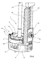
- FIG. 1 shows a partial perspective view of a bobbin for a braiding machine according to the invention in a first embodiment.
- the clapper is essentially composed of a bobbin 1, a brake system 2 associated with the bobbin 1 with two brake shoes 3, 4 and a yarn tensioning device 5 together.
- the thread tensioning device 5 has a trigger 6 assigned to the brake system 2.
- the brake shoes 3, 4 are each connected via a pivot bearing 9, 10 with an actuator 7, 8 and the actuators 7, 8 are connected via a sliding bearing 11 with the trigger 6.
- the sliding bearing 11 is designed as a knee joint, the knee lever are hinged to the brake shoes 3, 4 actuators 7, 8.
- the sliding bearing 11 has an axis formed on the trigger 6 axis 12 and formed respectively on the actuators 7, 8 elongated holes 13, with which the actuators 6, 7 are mounted rotatably mounted on the axis 12.
- the thread tensioning device has a locking slide 14 which is guided in the direction of the axis of symmetry of the knee lever formed by the actuators 7, 8.
- the locking slide 14 serves as a guide for a cocking slide 15 arranged on it.
- the brake shoes 3, 4 are articulated by means of bearing bolts 16, 17 on the base 18 of the bobbin and on their sides facing away from the bearing pin 16, 17 sides by means of a tension spring 19 against a brake pad of a ratchet wheel pulled, which is placed on the ball bearing 20.
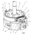
- FIG. 2 shows a rotated by 90 degrees partial view of the bobbin according to the FIG. 1 , From the FIG. 2 It can be seen that the brake shoes 3, 4 are pulled by means of the tension spring against the ratchet wheel 22, wherein an interposed brake pad 21 is part of the brake shoes 3, 4 or the ratchet wheel 22.
- the guided on a guide rod 23 cocking slide 15 carries a yarn guide roller 24 and guided on the guide rod 25 locking slide carries the trigger 6.
- the same components are provided with the same reference numerals.
- FIG. 3 shows an enlarged partial view according to Fig. 2 , but without representation of the thread tensioning device.
- the same components are also provided here with the same reference numbers.
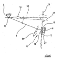
- FIG. 4 shows a schematic diagram of the kinematics of the brake system for the bobbin invention.
- the brake shoe 4 is shown as a floating bearing and the trigger 6 as a fixed bearing.
- the brake shoe 4 and the trigger 6 are connected to each other via the actuator 8, wherein the connection between the brake shoe 4 and the actuator 8 is made via the pivot bearing 10 and the connection between the trigger 6 and the actuator 8 is made via the sliding bearing 11. From this representation, it can be seen that the rotary bearing 10 and the longitudinal axis of the elongated hole 13 at right angles passing radial 27 extends outside of the elongated hole 13 of the sliding bearing 11.
- the rotary bearing 10 facing the soffit surface 28 of the elongated hole 13 acts as a sliding surface and the pivot bearing 10 facing soffit surface 29 of the elongated hole 13 acts as a driver surface.
- the brake shoe 4 moves in the direction of arrow 30 so that the actuator 8 slips down with its designed as a guide surface soffit surface 28 on the axis 12 of the trigger 6 and the actuator 8 rotates in the direction of arrow 31.
- a horizontal axis 32 and a vertical axis 33 are shown in the schematic diagram.
- the Fig. 5 shows a partial perspective view of the bobbin according to the invention in a second embodiment.
- the clapper is also composed here essentially of a bobbin 1, a coil carrier 1 associated brake system 2 'with a single brake shoe 3' and a yarn tensioning device 5 together.
- the thread tensioning device 5 has a trigger 6 'assigned to the brake system 2'.
- the brake shoe 3 ' is connected via a pivot bearing 9' with an actuator 7 'and the actuator 7' is connected via a sliding bearing 11 'with the trigger 6'.
- the articulated on the brake shoe 3 'actuator 7' together with a support member 8 'from a toggle lever, the knee joint 34 is supported on a lever arm 35.
- the support member 8 ' is articulated via a pivot bearing 10' on the base 18 of the clapper 19.
- the sliding bearing 11 ' has a cooperating with the trigger 6' axis 12 'and formed on the lever arm 35 slot 13', with which the lever arm 35 is mounted on the axis 12 '.
- the brake shoe 3 ' is pulled by means of the tension spring 19 against the ratchet wheel 22 (shown disassembled), wherein the brake pad 21 is mounted on the inside of the brake shoe 3'.
- the pivot bearing 10 'of the support member 8' and the pivot bearing 36 of the lever arm 35 are arranged on a base part 37 which is held by means of a clamping plate 38 in the vertical direction adjustable in the base 18.
- the same components are provided with the same reference numbers.
Landscapes
- Engineering & Computer Science (AREA)
- Textile Engineering (AREA)
- Braking Arrangements (AREA)
- Braiding, Manufacturing Of Bobbin-Net Or Lace, And Manufacturing Of Nets By Knotting (AREA)
Applications Claiming Priority (1)
| Application Number | Priority Date | Filing Date | Title |
|---|---|---|---|
| DE102007033163 | 2007-07-17 |
Publications (2)
| Publication Number | Publication Date |
|---|---|
| EP2017381A1 true EP2017381A1 (fr) | 2009-01-21 |
| EP2017381B1 EP2017381B1 (fr) | 2012-06-13 |
Family
ID=40039849
Family Applications (1)
| Application Number | Title | Priority Date | Filing Date |
|---|---|---|---|
| EP20080012922 Not-in-force EP2017381B1 (fr) | 2007-07-17 | 2008-07-17 | Fuseau à dentelle pour une machine à tresser |
Country Status (3)
| Country | Link |
|---|---|
| EP (1) | EP2017381B1 (fr) |
| DE (1) | DE102008033561A1 (fr) |
| ES (1) | ES2387695T3 (fr) |
Cited By (1)
| Publication number | Priority date | Publication date | Assignee | Title |
|---|---|---|---|---|
| CN105002651A (zh) * | 2015-08-25 | 2015-10-28 | 新昌县本发机电有限公司 | 编织机锭子刹车装置的定位套部件 |
Families Citing this family (7)
| Publication number | Priority date | Publication date | Assignee | Title |
|---|---|---|---|---|
| DE102011118108B3 (de) | 2011-11-09 | 2013-04-25 | Admedes Schuessler Gmbh | Klöppel für eine Flechtmaschine und eine mit diesem ausgestattete Flechtmaschine sowie Verfahren zum Aufbringen einer Spannung auf ein Flechtmaterial |
| DE102014016381B4 (de) | 2014-11-06 | 2016-07-14 | Admedes Schuessler Gmbh | Klöppel für eine Flechtmaschine, Flechtmaschine sowie Verfahren zum Steuern und Regeln einer auf ein Flechtmaterial aufgebrachten Spannung |
| DE102019101619B4 (de) | 2019-01-23 | 2022-04-07 | ADMEDES GmbH | Klöppel für eine Flechtmaschine, Flechtmaschine und Verfahren zum Erzeugen einer Zugspannung in Flechtmaterial beim Flechten |
| CN113005632A (zh) | 2019-12-19 | 2021-06-22 | 财团法人工业技术研究院 | 线材张力控制装置及应用其之编织机 |
| TWI772991B (zh) | 2020-12-02 | 2022-08-01 | 財團法人工業技術研究院 | 編織路徑生成方法與裝置以及動態修正方法與編織系統 |
| DE102022100620A1 (de) | 2022-01-12 | 2023-07-13 | Hahn-Schickard-Gesellschaft für angewandte Forschung e.V. | Sensorischer klöppel zur drahtlosen adaptiven spannungsregelung für die materialspezifische prozessauslegung |
| KR102875934B1 (ko) * | 2023-07-20 | 2025-11-04 | 백두영 | 편조기용 캐리어 |
Citations (3)
| Publication number | Priority date | Publication date | Assignee | Title |
|---|---|---|---|---|
| US2560084A (en) | 1947-05-23 | 1951-07-10 | Carter Ben | Carrier for braiding and like machines |
| GB881042A (en) | 1957-08-14 | 1961-11-01 | Btr Industries Ltd | Improvements relating to spool-carriers |
| DD69422A1 (de) | 1968-03-06 | 1969-10-20 | Einstellbare Spulenbremse für Flecht und Klöppelmaschinen |
-
2008
- 2008-07-17 ES ES08012922T patent/ES2387695T3/es active Active
- 2008-07-17 EP EP20080012922 patent/EP2017381B1/fr not_active Not-in-force
- 2008-07-17 DE DE102008033561A patent/DE102008033561A1/de not_active Withdrawn
Patent Citations (3)
| Publication number | Priority date | Publication date | Assignee | Title |
|---|---|---|---|---|
| US2560084A (en) | 1947-05-23 | 1951-07-10 | Carter Ben | Carrier for braiding and like machines |
| GB881042A (en) | 1957-08-14 | 1961-11-01 | Btr Industries Ltd | Improvements relating to spool-carriers |
| DD69422A1 (de) | 1968-03-06 | 1969-10-20 | Einstellbare Spulenbremse für Flecht und Klöppelmaschinen |
Cited By (1)
| Publication number | Priority date | Publication date | Assignee | Title |
|---|---|---|---|---|
| CN105002651A (zh) * | 2015-08-25 | 2015-10-28 | 新昌县本发机电有限公司 | 编织机锭子刹车装置的定位套部件 |
Also Published As
| Publication number | Publication date |
|---|---|
| DE102008033561A1 (de) | 2009-02-05 |
| EP2017381B1 (fr) | 2012-06-13 |
| ES2387695T3 (es) | 2012-09-28 |
Similar Documents
| Publication | Publication Date | Title |
|---|---|---|
| EP2017381B1 (fr) | Fuseau à dentelle pour une machine à tresser | |
| DE102009005543B4 (de) | Spannvorrichtung mit zwei Paaren von Drehwalzen an einem Verschiebungskörper | |
| DE10219148C1 (de) | Linearzuspannvorrichtung für eine Scheibenbremse | |
| EP1820982B1 (fr) | Dispositif de guidage linéaire doté d'un dispositif de réglage de pré-tension | |
| EP1709888B1 (fr) | Dispositif de guidage pour une chaise | |
| DE102014104870A1 (de) | Mechanik für einen Bürostuhl | |
| DE102016212511B4 (de) | Fahrzeugtürgriffvorrichtung | |
| DE69300087T2 (de) | Vorrichtung zur Einstellung der Schafthöhenlage bei Exzenterschaftmaschinen. | |
| EP0899231B1 (fr) | Dispositif de freinage à double action | |
| EP4077190B1 (fr) | Dispositif d'arrêt pour un ascenseur | |
| DE19607680A1 (de) | Gelenksondenkopf | |
| DE1477405C3 (de) | Einstellvorrichtung für Werkzeugträger, insbesondere für Bohrstangen von Feinbohrmaschinen mit einer drehbaren Bohrspindel | |
| DE69613762T2 (de) | Verstellbare Klammer für die Schwenkverbindung der Schwingarme einer Schaftmaschine mit den Hebeln des Hebesystems | |
| DE3531833A1 (de) | Vorrichtung zur einstellung des spiels zwischen einem halteelement und einem linear bewegbaren element | |
| DE10131272B4 (de) | Wendevorrichtung | |
| EP1630119A1 (fr) | Attache de fin de câble pour ascenseur | |
| WO2008128556A1 (fr) | Dispositif d'arrêt pour équipement d'optique médicale, en particulier pour moniteur | |
| DE19721115C1 (de) | Vorrichtung zum Auf-, Abwickeln und Zwischenspeichern mindestens einer Leitung und Gerät mit einer solchen Vorrichtung | |
| EP3177554B1 (fr) | Dispositif de guidage de bande et dispositif servant à transformer une bande de matériau | |
| DE102020103823B3 (de) | Drehmomentstütze zum Abfangen von Antriebsmomenten und Walzenanordnung mit einer Drehmomentstütze | |
| DE19963054C2 (de) | Fußpedalvorrichtung für ein Musikinstrument | |
| EP0334016B1 (fr) | Dispositif d'entraînement de la lame de pliage d'une machine à plier | |
| EP4104966B1 (fr) | Dispositif de serrage | |
| WO2020016060A1 (fr) | Groupe de cylindres, dispositif de broyage et procédé de réglage de la fente de broyage d'un dispositif de broyage | |
| EP1650590A1 (fr) | Dispositif d'ajustement destiné au positionnement très précis d'un objet |
Legal Events
| Date | Code | Title | Description |
|---|---|---|---|
| PUAI | Public reference made under article 153(3) epc to a published international application that has entered the european phase |
Free format text: ORIGINAL CODE: 0009012 |
|
| AK | Designated contracting states |
Kind code of ref document: A1 Designated state(s): AT BE BG CH CY CZ DE DK EE ES FI FR GB GR HR HU IE IS IT LI LT LU LV MC MT NL NO PL PT RO SE SI SK TR |
|
| AX | Request for extension of the european patent |
Extension state: AL BA MK RS |
|
| 17P | Request for examination filed |
Effective date: 20090421 |
|
| 17Q | First examination report despatched |
Effective date: 20090528 |
|
| AKX | Designation fees paid |
Designated state(s): DE ES FR GB IT |
|
| GRAP | Despatch of communication of intention to grant a patent |
Free format text: ORIGINAL CODE: EPIDOSNIGR1 |
|
| GRAS | Grant fee paid |
Free format text: ORIGINAL CODE: EPIDOSNIGR3 |
|
| GRAA | (expected) grant |
Free format text: ORIGINAL CODE: 0009210 |
|
| AK | Designated contracting states |
Kind code of ref document: B1 Designated state(s): DE ES FR GB IT |
|
| REG | Reference to a national code |
Ref country code: GB Ref legal event code: FG4D Free format text: NOT ENGLISH |
|
| REG | Reference to a national code |
Ref country code: DE Ref legal event code: R096 Ref document number: 502008007416 Country of ref document: DE Effective date: 20120809 |
|
| REG | Reference to a national code |
Ref country code: ES Ref legal event code: FG2A Ref document number: 2387695 Country of ref document: ES Kind code of ref document: T3 Effective date: 20120928 |
|
| PLBE | No opposition filed within time limit |
Free format text: ORIGINAL CODE: 0009261 |
|
| STAA | Information on the status of an ep patent application or granted ep patent |
Free format text: STATUS: NO OPPOSITION FILED WITHIN TIME LIMIT |
|
| 26N | No opposition filed |
Effective date: 20130314 |
|
| GBPC | Gb: european patent ceased through non-payment of renewal fee |
Effective date: 20120913 |
|
| REG | Reference to a national code |
Ref country code: DE Ref legal event code: R097 Ref document number: 502008007416 Country of ref document: DE Effective date: 20130314 |
|
| PG25 | Lapsed in a contracting state [announced via postgrant information from national office to epo] |
Ref country code: GB Free format text: LAPSE BECAUSE OF NON-PAYMENT OF DUE FEES Effective date: 20120913 |
|
| REG | Reference to a national code |
Ref country code: FR Ref legal event code: PLFP Year of fee payment: 8 |
|
| PGFP | Annual fee paid to national office [announced via postgrant information from national office to epo] |
Ref country code: ES Payment date: 20150723 Year of fee payment: 8 Ref country code: DE Payment date: 20150604 Year of fee payment: 8 |
|
| PGFP | Annual fee paid to national office [announced via postgrant information from national office to epo] |
Ref country code: FR Payment date: 20150730 Year of fee payment: 8 |
|
| PGFP | Annual fee paid to national office [announced via postgrant information from national office to epo] |
Ref country code: IT Payment date: 20150728 Year of fee payment: 8 |
|
| REG | Reference to a national code |
Ref country code: DE Ref legal event code: R119 Ref document number: 502008007416 Country of ref document: DE |
|
| PG25 | Lapsed in a contracting state [announced via postgrant information from national office to epo] |
Ref country code: FR Free format text: LAPSE BECAUSE OF NON-PAYMENT OF DUE FEES Effective date: 20160801 Ref country code: DE Free format text: LAPSE BECAUSE OF NON-PAYMENT OF DUE FEES Effective date: 20170201 |
|
| REG | Reference to a national code |
Ref country code: FR Ref legal event code: ST Effective date: 20170331 |
|
| PG25 | Lapsed in a contracting state [announced via postgrant information from national office to epo] |
Ref country code: IT Free format text: LAPSE BECAUSE OF NON-PAYMENT OF DUE FEES Effective date: 20160717 |
|
| PG25 | Lapsed in a contracting state [announced via postgrant information from national office to epo] |
Ref country code: ES Free format text: LAPSE BECAUSE OF NON-PAYMENT OF DUE FEES Effective date: 20160718 |
|
| REG | Reference to a national code |
Ref country code: ES Ref legal event code: FD2A Effective date: 20181130 |