EP2017384A2 - Dispositif de formation à tamis oblique d'une machine destinée à la fabrication d'une bande de matière fibreuse à partir d'au moins une suspension de matière fibreuse - Google Patents
Dispositif de formation à tamis oblique d'une machine destinée à la fabrication d'une bande de matière fibreuse à partir d'au moins une suspension de matière fibreuse Download PDFInfo
- Publication number
- EP2017384A2 EP2017384A2 EP08159838A EP08159838A EP2017384A2 EP 2017384 A2 EP2017384 A2 EP 2017384A2 EP 08159838 A EP08159838 A EP 08159838A EP 08159838 A EP08159838 A EP 08159838A EP 2017384 A2 EP2017384 A2 EP 2017384A2
- Authority
- EP
- European Patent Office
- Prior art keywords
- suction
- wire former
- sieve
- inclined wire
- width
- Prior art date
- Legal status (The legal status is an assumption and is not a legal conclusion. Google has not performed a legal analysis and makes no representation as to the accuracy of the status listed.)
- Granted
Links
- 239000000725 suspension Substances 0.000 title claims description 20
- 239000002657 fibrous material Substances 0.000 title 1
- 230000002093 peripheral effect Effects 0.000 claims abstract description 6
- 238000006073 displacement reaction Methods 0.000 claims description 9
- 238000011144 upstream manufacturing Methods 0.000 claims description 7
- 210000000481 breast Anatomy 0.000 claims description 6
- 239000000835 fiber Substances 0.000 claims description 5
- 230000000694 effects Effects 0.000 claims description 3
- 239000000446 fuel Substances 0.000 claims description 2
- 239000000463 material Substances 0.000 claims description 2
- 238000007789 sealing Methods 0.000 claims description 2
- 239000011888 foil Substances 0.000 abstract 1
- XLYOFNOQVPJJNP-UHFFFAOYSA-N water Substances O XLYOFNOQVPJJNP-UHFFFAOYSA-N 0.000 description 6
- 239000011248 coating agent Substances 0.000 description 2
- 238000000576 coating method Methods 0.000 description 2
- 238000005516 engineering process Methods 0.000 description 2
- 239000004744 fabric Substances 0.000 description 2
- 241000196324 Embryophyta Species 0.000 description 1
- 240000001439 Opuntia Species 0.000 description 1
- 235000004727 Opuntia ficus indica Nutrition 0.000 description 1
- 230000015572 biosynthetic process Effects 0.000 description 1
- 238000004140 cleaning Methods 0.000 description 1
- 230000018044 dehydration Effects 0.000 description 1
- 238000006297 dehydration reaction Methods 0.000 description 1
- 230000001419 dependent effect Effects 0.000 description 1
- 238000007865 diluting Methods 0.000 description 1
- 238000010790 dilution Methods 0.000 description 1
- 239000012895 dilution Substances 0.000 description 1
- 230000007613 environmental effect Effects 0.000 description 1
- 238000002474 experimental method Methods 0.000 description 1
- 238000004519 manufacturing process Methods 0.000 description 1
- 239000000203 mixture Substances 0.000 description 1
- 239000004745 nonwoven fabric Substances 0.000 description 1
Images

Classifications
-
- D—TEXTILES; PAPER
- D21—PAPER-MAKING; PRODUCTION OF CELLULOSE
- D21F—PAPER-MAKING MACHINES; METHODS OF PRODUCING PAPER THEREON
- D21F9/00—Complete machines for making continuous webs of paper
- D21F9/02—Complete machines for making continuous webs of paper of the Fourdrinier type
-
- D—TEXTILES; PAPER
- D21—PAPER-MAKING; PRODUCTION OF CELLULOSE
- D21F—PAPER-MAKING MACHINES; METHODS OF PRODUCING PAPER THEREON
- D21F1/00—Wet end of machines for making continuous webs of paper
- D21F1/48—Suction apparatus
- D21F1/52—Suction boxes without rolls
-
- D—TEXTILES; PAPER
- D21—PAPER-MAKING; PRODUCTION OF CELLULOSE
- D21F—PAPER-MAKING MACHINES; METHODS OF PRODUCING PAPER THEREON
- D21F1/00—Wet end of machines for making continuous webs of paper
- D21F1/48—Suction apparatus
- D21F1/52—Suction boxes without rolls
- D21F1/523—Covers thereof
Definitions
- the invention relates to a Schrägsiebformer a machine for producing a fibrous web, in particular a Langfaserpapier- or wet nonwoven web, at least one pulp suspension with a sieve, which runs over a peripheral region of a breast roll and then in the direction of wire running at least in sections at a preferably oblique angle to the horizontal, wherein in this preferably oblique section of the screen at least one headbox which applies at least one fibrous suspension on top of the sieve, wherein at least one drainage element for dewatering the at least one applied to the screen pulp suspension is arranged on the underside of the screen and wherein the suction element formed as a drainage element to the sieve out is open to exert a suction effect on the screen and the at least one on the top side applied pulp suspension, and a plurality of the sieve touching and to Having spaced drainage strips which extend transversely to the wire direction and define a plurality of suction slots.
- Schrägsiebformer is for example from the German patent application DE 10 2004 047 518 A1 and is manufactured and sold by the applicant under the name "HydroFormer". It is used primarily for the production of long fiber papers and wet nonwovens, this type of sheet formation fibers and fiber mixtures of various materials are used with a length of 1 to 40 mm.
- the dewatering width of this Schrägsiebformers is generally determined by the clear box width of the headbox.
- This clear box width essentially determines the width of the fibrous web to be produced and is a constructive basic feature of the headbox, which can not be changed easily.
- At least one suction slot of the suction box is provided in the two edge zones of the screen, each with a sliding intermediate strip, which is fitted in each case sealingly between the two adjacent drainage strips, wherein the intermediate strips of a suction slot together determine a suction zone width which is smaller than the width of the screen.
- the width of the fibrous web to be produced is significantly determined by the dewatering width of the Schrägsiebformers. If the dewatering width is now reduced or increased independently of the clear box width of the headbox, the width of the fibrous web to be produced also changes correspondingly due to generated transverse flows in the at least one pulp suspension applied to the wire as a result of the light suction of the suction box.
- the at least one pulp suspension applied to the sieve therefore experiences a reduction or enlargement with regard to its applied width, which is ultimately fixed on account of the dehydration and the at least one pulp suspension. And this fixed width of at least one applied to the screen pulp suspension ultimately represents the width of the fibrous web to be produced.
- the change in the width of the fibrous web to be produced can also be performed effectively and reliably, in a preferred embodiment, several, preferably all suction slots of the suction box in the two edge zones of the screen, each provided with a sliding intermediate strip.
- intermediate strips can be individually, in groups or together displaced.
- These possibilities presented allow a locally individual, fast, precise and effective change of the drainage width of the Schrägsiebformers and thus the Width of the fibrous web to be produced.
- the format of the fibrous web to be produced can be changed directly and quickly.
- the basis weight in the corresponding edge region of the fibrous web to be produced can be influenced.
- the individual intermediate strip is preferably directly or indirectly, for example by means of a acted upon by at least one actuator slide plate, displaceable. This allows a fast and precise shift with excellent repeatability.
- the immediate displacement of an intermediate strip can for example be done manually, if necessary with the aid of a template or a measuring device.
- At least one cover plate is arranged, which supports the slide plate surface.
- This cover plate gives the system a sufficient degree of stability and ensures a continuous reliability in terms of possible shifts.
- the cover plate preferably carries the lower side and the actuator so that it is on the one hand safely mounted and on the other hand is sufficiently protected against potentially harmful environmental influences.
- the actuator comprises a spindle drive which acts on the slide plate via at least one spindle drive.
- the actuator can be an electrical, an electromechanical, a magnetic, a pneumatic and / or a hydraulic drive.
- the intermediate strip preferably has a displacement in the range of 1 to 500 mm, preferably from 25 to 200 mm, in particular from 50 to 150 mm.
- the intermediate strip and its two adjacent drainage strips ideally have an overlap in the range of 100 to 400 mm, preferably from 125 to 300 mm, in particular from 50 to 150 mm, so that a sufficiently stable and sealing guidance of the individual intermediate strips can be ensured ,
- the suction zone width of the suction box is preferably in the range of 1,000 to 11,000 mm, preferably in the range of 1,800 to 10,000 mm, especially 3,000 to 8,000. These areas can easily meet current and future requirements.
- the sieve can be performed as gently and wear-resistant on the suction box, it is in the direction of the wire directly upstream of the sieve plate facing arranged with a preferably curved guide surface.
- the headbox may be designed as a multi-layer headbox, wherein preferably a sectioned fuel density control is provided for at least one layer of the multi-layer headbox.
- at least two headboxes may be arranged on the inclined wire former, wherein preferably a sectioned fabric density control is provided for at least one layer of a headbox.
- FIG. 1 shows a schematic side view of a Schrägsiebformers 1 of a machine for producing a fibrous web 2, in particular a long fiber paper or wet nonwoven web, from at least one pulp suspension.
- the Schrägsiebformer 1 has a screen 4, which runs over a peripheral region 6 of a breast roll 5 and then in the wire direction S (arrow) at least in sections at an angle ⁇ obliquely to the horizontal H, wherein the angle ⁇ has a value in the range of 0 ° to 45 ° can assume. In the present embodiment, the angle ⁇ is about 20 °.
- a dewatering element 9 is arranged for dewatering the applied to the sieve 4 pulp suspension 3.
- the headbox 8 is arranged such that it applies in the region of the dewatering element 9, the preferably complete pulp suspension 3 on the sieve 4, the front wall 8.1 of the headbox 8 thus ends in the end region of the dewatering element 9 and thus forms an outlet gap A.
- the drainage element 9 could also go beyond the application area of the headbox 8.
- the Indian FIG. 1 illustrated headbox 8 is a conventional headbox of known design and proven operation. It may be formed in a further embodiment as a multi-layer casserole, preferably a sectioned consistency control (dilution water technology) is provided for at least one layer of this multi-layer casserole. Or at least two headboxes may be arranged in the area of the inclined wire former, wherein preferably a sectioned fabric density control ("diluting water technology") is provided for at least one headbox.
- a sectioned consistency control is, for example, in the German patent DE 40 19 593 C2 shown and described.
- the illustrated drainage element 9 is designed as a suction box 10 known to those skilled in the art, which is open to the wire 4, to exert a suction effect on the wire 4 and the at least one pulp suspension 3 applied on the upper side of the wire 4. Furthermore, the suction box 10 a plurality of the sieve 4 touching and spaced apart drainage strips 11, which extend transversely to the wire direction S (arrow) and define a plurality of suction slots 12.
- the suction box 10 also has, for example, five suction zones Z 1 to Z 5 in the direction of the wire run S (arrow).
- the number of suction zones of the suction box 10 as a rule moves between four and eight suction zones, preferably between five and six suction zones.
- the suction zones Z 1 to Z 5 of the suction box 10 shown can be acted upon by at least two different subpressures U 1 , U 2 generated by two separate vacuum sources 13. 1 , 13. 2 for the zones Z 1 , Z 2 , Z 3 and Z 4 , Z 5 become.
- the vacuum sources 13.1, 13.2 may be designed, for example, as preferably controllable / controllable vacuum pumps. Of course, only a vacuum source may be present, which preferably engages in the lower region of the suction box.
- White water 14 is by means of a white water drain 15 off and the known white water circuit fed. Also, instead of a single suction box 10 more consecutively arranged su
- the wire 4 together with overlying fibrous web 2 is guided over a guide roller 16 before the fibrous web 2 is removed in a known manner from the wire 4 and fed to other machine sections.
- the screen 4 is then returned to the breast roll 5 via a plurality of guide rollers 17. During this recirculation, the screen 4 is usually cleaned by means of a known cleaning device.
- At least one of the screen 4 leading element such as the breast roll 5 be connected to at least one acting on him shaker to the oscillating movement transverse to the wire direction S (arrow).
- a shaking plant is basically the known prior art, is for example from the German patent application DE 197 04 730 A1 or from the German Utility Model G 93 17 640 U1 and is manufactured and sold by the applicant under the name "DuoShake".
- the suction slots 12 of the suction box 10 are now in the two edge zones R R , R L of the sieve 4 - seen in the wire direction S (arrow) - each provided with a sliding intermediate strip 18, which sealingly fitted between the two adjacent drainage strips 11, wherein the intermediate strips 18 of a suction slot 12 together determine a suction zone width B Z , which is smaller than the width B 4 of the sieve 4 (see. FIG. 2 ).
- the respective intermediate strip 18 thus has, at least in regions, along its height, the opposite contour of the drainage strip 11 which is in each case adjacent to one another.
- the on one side of the suction box 10 in its rand wornem area 10R, 10L arranged intermediate strips 18 are individually, in groups or jointly displaced.
- the single intermediate strip 18 is direct or indirect, For example, by means of a acted upon by at least one actuator 20 slide plate 19, displaceable (see. FIG. 2 ) .
- the suction box 10 in the wire direction S (arrow) directly upstream of a sieve 4 leading plate coating 21 with a preferably curved guide surface F21 upstream.
- the length L21 of the guide surface F21 in the wire running direction S (arrow) is in a range of 150 to 400 mm, preferably 200 to 350 mm.
- the plate covering 21 is externally fixedly mounted on the respective cover plate 22 of the suction box 10, for example by means of several screw 23 (see. FIG. 3 ).
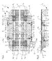
- FIG. 2 shows a plan view of the suction box 10 of a Schrägsiebformers invention 1.
- the top view is provided with a section.
- the suction slots 12 of the suction box 10 are, as already stated, in the two edge zones R R , R L of the screen 4 - seen in the wire direction S (arrow) - each provided with a sliding intermediate strip 18, which fitted sealingly between the two adjacent drainage strips 11 are, wherein the intermediate strips 18 of a suction slot 12 together determine a suction zone width B Z , which is smaller than the width B 4 of the screen 4.
- the suction zone width B Z of the suction box 10 is in the range of 1,000 to 11,000 mm, preferably in the range of 1,800 to 10,000 mm, in particular from 3,000 to 8,000. There are, again for clarity, only the in the beginning and end of the suction box 10 - seen in the wire direction (S) - mounted intermediate strips 18 shown.
- the arranged on one side of the suction box 10 intermediate strips 18 are jointly displaceable in the present embodiment, but they can also be individually or in groups displaced.
- the common displacement takes place indirectly, for example by means of an acted upon by an actuator 20 slide plate 19.
- the individual actuator 20 includes in In the present embodiment, a spindle drive 20.1, which acts on two spindle gear 20.21, 20.22 the slide plate 19.
- the individual components 20.1, 20.21, 20.22 are connected to each other via drive shafts 20.31, 20.32.
- a contoured cover plate 22 is arranged, which supports the associated slide plate 19 flat.
- the respective cover plate 22 is provided with corresponding recesses 24 to allow the loading of the mounted slide plate 19 by the spindle gear 20.21, 20.22.
- the suction box 10 is in the wire direction S (arrow) also directly upstream of a sieve 4 leading plate coating 21 with a preferably curved guide surface F 21 upstream.
- the length L 21 of the guide surface F 21 in the wire direction S (arrow) is in a range of 150 to 400 mm, preferably from 200 to 350 mm.
- FIG. 3 shows a longitudinal sectional view of the suction box 10 of the Schrägsiebformers 1 of the invention FIG. 2 ,
- the longitudinal section is also provided with a cut.
- suction slots 12 of the suction box 10 are provided in the edge zone R L of the screen 4, each with a displaceable intermediate strip 18, which are sealingly fitted between the two adjacent drainage strips 11.
- the cover plate 22 is arranged, which supports the associated slide plate 20 flat.
- On the respective cover plate 22 and the lining plate 21 of the suction box 10 is mounted with a preferably curved guiding surface F 21, 23 for example by means of several screw connections
- the length L 21 of the guide surface 21 in F Sieblaufraum S (arrow) is in a range of 150 to 400 mm, preferably from 200 to 350 mm.
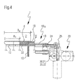
- FIG. 4 shows a marginal and top sectional view of the suction box 10 of the Schrägsiebformers 1 of the invention FIG. 2 according to the section line XX.
- the suction box 10 is provided in its edge region 10 R with a contoured cover plate 22 which supports the associated slide plate 19 by support surface. Below the cover plate 22 of the slide plate 19 acting actuator 20 is arranged by means of a plurality of brackets 25.
- the cover plate 22 is provided with corresponding recesses 24 to allow the loading of the slide plate 19 by the spindle gear 20.21, 20.22.
- the two intermediate strips 18 of a suction slot 12 together determine the suction zone width B Z , which is smaller than the width B 4 of the sieve 4.
- the suction zone width B Z of the suction box 10 is in the range of 1,000 to 11,000 mm, preferably in the range of 1,800 to 10,000 mm, in particular from 3,000 to 8,000.
- the respective intermediate strip 18 has a displacement path V in the range from 1 to 500 mm, preferably from 25 to 200 mm, in particular from 50 to 150 mm, so that it and its two adjacent drainage strips 11 have a coverage Ü in the range from 100 to 400 mm, preferably from 125 to 300 mm, in particular from 50 to 150 mm.
- the two characteristics displacement path V and coverage Ü are merely indicated because they are sufficiently known to the skilled person.
- the invention provides a Schrägsiebformer of the type mentioned, which is a change in the width of the fibrous web to be produced in particular during its operation and in particular in larger latitudes. This possibility of change is also subject to simple handling and is characterized by only minor additional costs in acquisition and operation.
Landscapes
- Paper (AREA)
Applications Claiming Priority (1)
| Application Number | Priority Date | Filing Date | Title |
|---|---|---|---|
| DE200710033395 DE102007033395A1 (de) | 2007-07-18 | 2007-07-18 | Schrägsiebformer einer Maschine zur Herstellung einer Faserstoffbahn aus wenigstens einer Faserstoffsuspension |
Publications (3)
| Publication Number | Publication Date |
|---|---|
| EP2017384A2 true EP2017384A2 (fr) | 2009-01-21 |
| EP2017384A3 EP2017384A3 (fr) | 2011-05-18 |
| EP2017384B1 EP2017384B1 (fr) | 2012-12-05 |
Family
ID=39865103
Family Applications (1)
| Application Number | Title | Priority Date | Filing Date |
|---|---|---|---|
| EP20080159838 Not-in-force EP2017384B1 (fr) | 2007-07-18 | 2008-07-07 | Dispositif de formation à tamis oblique d'une machine destinée à la fabrication d'une bande de matière fibreuse à partir d'au moins une suspension de matière fibreuse |
Country Status (2)
| Country | Link |
|---|---|
| EP (1) | EP2017384B1 (fr) |
| DE (1) | DE102007033395A1 (fr) |
Cited By (4)
| Publication number | Priority date | Publication date | Assignee | Title |
|---|---|---|---|---|
| CN103290718A (zh) * | 2012-02-24 | 2013-09-11 | 胡正富 | 造纸设备 |
| US20130269898A1 (en) * | 2010-12-17 | 2013-10-17 | Oji Holdings Corporation | Device for producing fibrous sheet |
| CN110777554A (zh) * | 2019-10-28 | 2020-02-11 | 华南理工大学 | 一种基于吸水箱的横幅定量调节方法及斜网成型器 |
| CN118581758A (zh) * | 2024-06-03 | 2024-09-03 | 河南逸祥卫生科技有限公司 | 一种湿法成网工艺 |
Families Citing this family (2)
| Publication number | Priority date | Publication date | Assignee | Title |
|---|---|---|---|---|
| DE102015001008A1 (de) | 2015-01-28 | 2016-07-28 | Andritz Küsters Gmbh | Verfahren und Vorrichtung zur Herstellung von nassgelegten Vliesstoffen |
| DE102015005384A1 (de) | 2015-04-28 | 2016-11-03 | Andritz Küsters Gmbh | Verfahren und Vorrichtung zur Herstellung von nassgelegten Vliesstoffen |
Citations (5)
| Publication number | Priority date | Publication date | Assignee | Title |
|---|---|---|---|---|
| US4081321A (en) | 1975-11-06 | 1978-03-28 | J. M. Voith Gmbh | Movable deckle within headbox outlet |
| DE4019593C2 (de) | 1990-06-20 | 1994-01-20 | Voith Gmbh J M | Stoffauflauf für Papiermaschinen |
| DE9317640U1 (de) | 1993-11-18 | 1994-01-27 | Dörries GmbH, 52349 Düren | Einrichtung zur Walzenschüttelung |
| DE19704730A1 (de) | 1997-02-07 | 1998-08-13 | Voith Sulzer Papiermasch Gmbh | Schüttelvorrichtung |
| DE102004047518A1 (de) | 2004-09-28 | 2006-03-30 | Voith Paper Patent Gmbh | Verfahren und Schrägsiebformer einer Maschine zur Herstellung einer Faserstoffbahn aus mindestens einer Faserstoffsuspension |
Family Cites Families (1)
| Publication number | Priority date | Publication date | Assignee | Title |
|---|---|---|---|---|
| US5076894A (en) * | 1990-05-04 | 1991-12-31 | Simmons Holt W | Suction box apparatus with composite cover elements mounted in slots on cross braces |
-
2007
- 2007-07-18 DE DE200710033395 patent/DE102007033395A1/de not_active Withdrawn
-
2008
- 2008-07-07 EP EP20080159838 patent/EP2017384B1/fr not_active Not-in-force
Patent Citations (5)
| Publication number | Priority date | Publication date | Assignee | Title |
|---|---|---|---|---|
| US4081321A (en) | 1975-11-06 | 1978-03-28 | J. M. Voith Gmbh | Movable deckle within headbox outlet |
| DE4019593C2 (de) | 1990-06-20 | 1994-01-20 | Voith Gmbh J M | Stoffauflauf für Papiermaschinen |
| DE9317640U1 (de) | 1993-11-18 | 1994-01-27 | Dörries GmbH, 52349 Düren | Einrichtung zur Walzenschüttelung |
| DE19704730A1 (de) | 1997-02-07 | 1998-08-13 | Voith Sulzer Papiermasch Gmbh | Schüttelvorrichtung |
| DE102004047518A1 (de) | 2004-09-28 | 2006-03-30 | Voith Paper Patent Gmbh | Verfahren und Schrägsiebformer einer Maschine zur Herstellung einer Faserstoffbahn aus mindestens einer Faserstoffsuspension |
Cited By (7)
| Publication number | Priority date | Publication date | Assignee | Title |
|---|---|---|---|---|
| US20130269898A1 (en) * | 2010-12-17 | 2013-10-17 | Oji Holdings Corporation | Device for producing fibrous sheet |
| US8845862B2 (en) * | 2010-12-17 | 2014-09-30 | Oji Holdings Corporation | Device for producing fibrous sheet |
| CN103290718A (zh) * | 2012-02-24 | 2013-09-11 | 胡正富 | 造纸设备 |
| CN103290718B (zh) * | 2012-02-24 | 2016-02-10 | 胡正富 | 造纸设备 |
| CN110777554A (zh) * | 2019-10-28 | 2020-02-11 | 华南理工大学 | 一种基于吸水箱的横幅定量调节方法及斜网成型器 |
| CN110777554B (zh) * | 2019-10-28 | 2021-10-26 | 华南理工大学 | 一种基于吸水箱的横幅定量调节方法及斜网成型器 |
| CN118581758A (zh) * | 2024-06-03 | 2024-09-03 | 河南逸祥卫生科技有限公司 | 一种湿法成网工艺 |
Also Published As
| Publication number | Publication date |
|---|---|
| DE102007033395A1 (de) | 2009-02-19 |
| EP2017384A3 (fr) | 2011-05-18 |
| EP2017384B1 (fr) | 2012-12-05 |
Similar Documents
| Publication | Publication Date | Title |
|---|---|---|
| EP2017384B1 (fr) | Dispositif de formation à tamis oblique d'une machine destinée à la fabrication d'une bande de matière fibreuse à partir d'au moins une suspension de matière fibreuse | |
| DE69221034T2 (de) | Siebbelastungsvorrichtung in einer Papiermaschine | |
| DE3329833C2 (de) | Vorrichtung zur Entwässerung einer Papierbahn oder dergleichen | |
| DE2641521B2 (de) | Papiermaschine, insbesondere zum Herstellen von Tissue-Papier | |
| DE69020106T2 (de) | Doppelsiebformer in einer Papiermaschine. | |
| DE3344217A1 (de) | Vorrichtung zum ueberfuehren einer papierbahn von der pressen- in die trockenpartie einer papiermaschine | |
| DE3045279C2 (fr) | ||
| DE2549726A1 (de) | Siebpartie einer maschine zum herstellen einer faserbahn | |
| DE69713104T2 (de) | Doppelsiebformer für eine papiermaschine | |
| DE602005002646T2 (de) | Vorrichtung und verfahren für eine papiermaschine | |
| EP0967323B1 (fr) | Section de formage à deux toiles | |
| AT9223U1 (de) | Entwässerungselement in der siebpartie einer materialbahn-herstellungsmaschine und deckel des entwässerungselements einer materialbahn-herstellungsmaschine | |
| DE1925407A1 (de) | Papierbildung | |
| DE2051048A1 (de) | Siebpartie einer Maschine zum Herstellen einer Faserbahn | |
| DE4002305A1 (de) | Entwaesserungsvorrichtung an einem doppelsiebformer | |
| DE3803805C1 (fr) | ||
| DE2826158A1 (de) | Verfahren und maschine zur herstellung von faserbahnen | |
| DE591715C (de) | Vorrichtung zum Regeln der Entwaesserung von Stoffbahnen auf Langsieben von Papier-, Karton- u. dgl. Maschinen | |
| DE2414388C3 (de) | Bahnbildungszone einer Langsieb-Papiermaschine | |
| DE60213359T2 (de) | Vorrichtung zur Herstellung einer Papier- oder Pappebahn | |
| DE1461074C3 (de) | Nasspresse für Papiermaschinen | |
| AT347228B (de) | Laufregulierungseinrichtung zur fuehrung eines bandes | |
| DE1511189C (de) | Entwässerungsvorrichtung für eine Langsieb-Papiermaschine | |
| DE102007000065A1 (de) | Verfahren zur Herstellung einer Faserstoffbahn und Doppelsiebformer zur Durchführung des Verfahrens | |
| DE3800801A1 (de) | Stationaere stuetzvorrichtung |
Legal Events
| Date | Code | Title | Description |
|---|---|---|---|
| PUAI | Public reference made under article 153(3) epc to a published international application that has entered the european phase |
Free format text: ORIGINAL CODE: 0009012 |
|
| AK | Designated contracting states |
Kind code of ref document: A2 Designated state(s): AT BE BG CH CY CZ DE DK EE ES FI FR GB GR HR HU IE IS IT LI LT LU LV MC MT NL NO PL PT RO SE SI SK TR |
|
| AX | Request for extension of the european patent |
Extension state: AL BA MK RS |
|
| PUAL | Search report despatched |
Free format text: ORIGINAL CODE: 0009013 |
|
| AK | Designated contracting states |
Kind code of ref document: A3 Designated state(s): AT BE BG CH CY CZ DE DK EE ES FI FR GB GR HR HU IE IS IT LI LT LU LV MC MT NL NO PL PT RO SE SI SK TR |
|
| AX | Request for extension of the european patent |
Extension state: AL BA MK RS |
|
| 17P | Request for examination filed |
Effective date: 20111118 |
|
| GRAP | Despatch of communication of intention to grant a patent |
Free format text: ORIGINAL CODE: EPIDOSNIGR1 |
|
| AKX | Designation fees paid |
Designated state(s): AT BE BG CH CY CZ DE DK EE ES FI FR GB GR HR HU IE IS IT LI LT LU LV MC MT NL NO PL PT RO SE SI SK TR |
|
| GRAS | Grant fee paid |
Free format text: ORIGINAL CODE: EPIDOSNIGR3 |
|
| 17Q | First examination report despatched |
Effective date: 20120612 |
|
| GRAA | (expected) grant |
Free format text: ORIGINAL CODE: 0009210 |
|
| AK | Designated contracting states |
Kind code of ref document: B1 Designated state(s): AT BE BG CH CY CZ DE DK EE ES FI FR GB GR HR HU IE IS IT LI LT LU LV MC MT NL NO PL PT RO SE SI SK TR |
|
| REG | Reference to a national code |
Ref country code: GB Ref legal event code: FG4D Free format text: NOT ENGLISH |
|
| REG | Reference to a national code |
Ref country code: CH Ref legal event code: EP |
|
| REG | Reference to a national code |
Ref country code: AT Ref legal event code: REF Ref document number: 587366 Country of ref document: AT Kind code of ref document: T Effective date: 20121215 |
|
| REG | Reference to a national code |
Ref country code: IE Ref legal event code: FG4D Free format text: LANGUAGE OF EP DOCUMENT: GERMAN |
|
| REG | Reference to a national code |
Ref country code: DE Ref legal event code: R096 Ref document number: 502008008819 Country of ref document: DE Effective date: 20130131 |
|
| PG25 | Lapsed in a contracting state [announced via postgrant information from national office to epo] |
Ref country code: LT Free format text: LAPSE BECAUSE OF FAILURE TO SUBMIT A TRANSLATION OF THE DESCRIPTION OR TO PAY THE FEE WITHIN THE PRESCRIBED TIME-LIMIT Effective date: 20121205 Ref country code: NO Free format text: LAPSE BECAUSE OF FAILURE TO SUBMIT A TRANSLATION OF THE DESCRIPTION OR TO PAY THE FEE WITHIN THE PRESCRIBED TIME-LIMIT Effective date: 20130305 Ref country code: ES Free format text: LAPSE BECAUSE OF FAILURE TO SUBMIT A TRANSLATION OF THE DESCRIPTION OR TO PAY THE FEE WITHIN THE PRESCRIBED TIME-LIMIT Effective date: 20130316 Ref country code: SE Free format text: LAPSE BECAUSE OF FAILURE TO SUBMIT A TRANSLATION OF THE DESCRIPTION OR TO PAY THE FEE WITHIN THE PRESCRIBED TIME-LIMIT Effective date: 20121205 |
|
| REG | Reference to a national code |
Ref country code: NL Ref legal event code: VDEP Effective date: 20121205 |
|
| REG | Reference to a national code |
Ref country code: LT Ref legal event code: MG4D |
|
| PG25 | Lapsed in a contracting state [announced via postgrant information from national office to epo] |
Ref country code: SI Free format text: LAPSE BECAUSE OF FAILURE TO SUBMIT A TRANSLATION OF THE DESCRIPTION OR TO PAY THE FEE WITHIN THE PRESCRIBED TIME-LIMIT Effective date: 20121205 Ref country code: CY Free format text: LAPSE BECAUSE OF FAILURE TO SUBMIT A TRANSLATION OF THE DESCRIPTION OR TO PAY THE FEE WITHIN THE PRESCRIBED TIME-LIMIT Effective date: 20121205 Ref country code: GR Free format text: LAPSE BECAUSE OF FAILURE TO SUBMIT A TRANSLATION OF THE DESCRIPTION OR TO PAY THE FEE WITHIN THE PRESCRIBED TIME-LIMIT Effective date: 20130306 Ref country code: LV Free format text: LAPSE BECAUSE OF FAILURE TO SUBMIT A TRANSLATION OF THE DESCRIPTION OR TO PAY THE FEE WITHIN THE PRESCRIBED TIME-LIMIT Effective date: 20121205 Ref country code: PL Free format text: LAPSE BECAUSE OF FAILURE TO SUBMIT A TRANSLATION OF THE DESCRIPTION OR TO PAY THE FEE WITHIN THE PRESCRIBED TIME-LIMIT Effective date: 20121205 |
|
| PG25 | Lapsed in a contracting state [announced via postgrant information from national office to epo] |
Ref country code: CZ Free format text: LAPSE BECAUSE OF FAILURE TO SUBMIT A TRANSLATION OF THE DESCRIPTION OR TO PAY THE FEE WITHIN THE PRESCRIBED TIME-LIMIT Effective date: 20121205 Ref country code: BG Free format text: LAPSE BECAUSE OF FAILURE TO SUBMIT A TRANSLATION OF THE DESCRIPTION OR TO PAY THE FEE WITHIN THE PRESCRIBED TIME-LIMIT Effective date: 20130305 Ref country code: IS Free format text: LAPSE BECAUSE OF FAILURE TO SUBMIT A TRANSLATION OF THE DESCRIPTION OR TO PAY THE FEE WITHIN THE PRESCRIBED TIME-LIMIT Effective date: 20130405 Ref country code: EE Free format text: LAPSE BECAUSE OF FAILURE TO SUBMIT A TRANSLATION OF THE DESCRIPTION OR TO PAY THE FEE WITHIN THE PRESCRIBED TIME-LIMIT Effective date: 20121205 Ref country code: SK Free format text: LAPSE BECAUSE OF FAILURE TO SUBMIT A TRANSLATION OF THE DESCRIPTION OR TO PAY THE FEE WITHIN THE PRESCRIBED TIME-LIMIT Effective date: 20121205 |
|
| PG25 | Lapsed in a contracting state [announced via postgrant information from national office to epo] |
Ref country code: RO Free format text: LAPSE BECAUSE OF FAILURE TO SUBMIT A TRANSLATION OF THE DESCRIPTION OR TO PAY THE FEE WITHIN THE PRESCRIBED TIME-LIMIT Effective date: 20121205 Ref country code: NL Free format text: LAPSE BECAUSE OF FAILURE TO SUBMIT A TRANSLATION OF THE DESCRIPTION OR TO PAY THE FEE WITHIN THE PRESCRIBED TIME-LIMIT Effective date: 20121205 Ref country code: PT Free format text: LAPSE BECAUSE OF FAILURE TO SUBMIT A TRANSLATION OF THE DESCRIPTION OR TO PAY THE FEE WITHIN THE PRESCRIBED TIME-LIMIT Effective date: 20130405 |
|
| PLBE | No opposition filed within time limit |
Free format text: ORIGINAL CODE: 0009261 |
|
| STAA | Information on the status of an ep patent application or granted ep patent |
Free format text: STATUS: NO OPPOSITION FILED WITHIN TIME LIMIT |
|
| PG25 | Lapsed in a contracting state [announced via postgrant information from national office to epo] |
Ref country code: DK Free format text: LAPSE BECAUSE OF FAILURE TO SUBMIT A TRANSLATION OF THE DESCRIPTION OR TO PAY THE FEE WITHIN THE PRESCRIBED TIME-LIMIT Effective date: 20121205 |
|
| 26N | No opposition filed |
Effective date: 20130906 |
|
| PG25 | Lapsed in a contracting state [announced via postgrant information from national office to epo] |
Ref country code: HR Free format text: LAPSE BECAUSE OF FAILURE TO SUBMIT A TRANSLATION OF THE DESCRIPTION OR TO PAY THE FEE WITHIN THE PRESCRIBED TIME-LIMIT Effective date: 20121205 |
|
| PG25 | Lapsed in a contracting state [announced via postgrant information from national office to epo] |
Ref country code: IT Free format text: LAPSE BECAUSE OF FAILURE TO SUBMIT A TRANSLATION OF THE DESCRIPTION OR TO PAY THE FEE WITHIN THE PRESCRIBED TIME-LIMIT Effective date: 20121205 |
|
| REG | Reference to a national code |
Ref country code: DE Ref legal event code: R097 Ref document number: 502008008819 Country of ref document: DE Effective date: 20130906 |
|
| BERE | Be: lapsed |
Owner name: VOITH PATENT G.M.B.H. Effective date: 20130731 |
|
| PG25 | Lapsed in a contracting state [announced via postgrant information from national office to epo] |
Ref country code: MC Free format text: LAPSE BECAUSE OF FAILURE TO SUBMIT A TRANSLATION OF THE DESCRIPTION OR TO PAY THE FEE WITHIN THE PRESCRIBED TIME-LIMIT Effective date: 20121205 |
|
| REG | Reference to a national code |
Ref country code: CH Ref legal event code: PL |
|
| GBPC | Gb: european patent ceased through non-payment of renewal fee |
Effective date: 20130707 |
|
| REG | Reference to a national code |
Ref country code: IE Ref legal event code: MM4A |
|
| REG | Reference to a national code |
Ref country code: DE Ref legal event code: R119 Ref document number: 502008008819 Country of ref document: DE Effective date: 20140201 |
|
| REG | Reference to a national code |
Ref country code: FR Ref legal event code: ST Effective date: 20140331 |
|
| PG25 | Lapsed in a contracting state [announced via postgrant information from national office to epo] |
Ref country code: GB Free format text: LAPSE BECAUSE OF NON-PAYMENT OF DUE FEES Effective date: 20130707 Ref country code: FI Free format text: LAPSE BECAUSE OF NON-PAYMENT OF DUE FEES Effective date: 20130707 Ref country code: CH Free format text: LAPSE BECAUSE OF NON-PAYMENT OF DUE FEES Effective date: 20130731 Ref country code: LI Free format text: LAPSE BECAUSE OF NON-PAYMENT OF DUE FEES Effective date: 20130731 Ref country code: BE Free format text: LAPSE BECAUSE OF NON-PAYMENT OF DUE FEES Effective date: 20130731 Ref country code: DE Free format text: LAPSE BECAUSE OF NON-PAYMENT OF DUE FEES Effective date: 20140201 |
|
| PG25 | Lapsed in a contracting state [announced via postgrant information from national office to epo] |
Ref country code: FR Free format text: LAPSE BECAUSE OF NON-PAYMENT OF DUE FEES Effective date: 20130731 |
|
| PG25 | Lapsed in a contracting state [announced via postgrant information from national office to epo] |
Ref country code: IE Free format text: LAPSE BECAUSE OF NON-PAYMENT OF DUE FEES Effective date: 20130707 |
|
| REG | Reference to a national code |
Ref country code: AT Ref legal event code: MM01 Ref document number: 587366 Country of ref document: AT Kind code of ref document: T Effective date: 20130707 |
|
| PG25 | Lapsed in a contracting state [announced via postgrant information from national office to epo] |
Ref country code: AT Free format text: LAPSE BECAUSE OF NON-PAYMENT OF DUE FEES Effective date: 20130707 |
|
| PG25 | Lapsed in a contracting state [announced via postgrant information from national office to epo] |
Ref country code: TR Free format text: LAPSE BECAUSE OF FAILURE TO SUBMIT A TRANSLATION OF THE DESCRIPTION OR TO PAY THE FEE WITHIN THE PRESCRIBED TIME-LIMIT Effective date: 20121205 Ref country code: MT Free format text: LAPSE BECAUSE OF FAILURE TO SUBMIT A TRANSLATION OF THE DESCRIPTION OR TO PAY THE FEE WITHIN THE PRESCRIBED TIME-LIMIT Effective date: 20121205 |
|
| PG25 | Lapsed in a contracting state [announced via postgrant information from national office to epo] |
Ref country code: LU Free format text: LAPSE BECAUSE OF NON-PAYMENT OF DUE FEES Effective date: 20130707 Ref country code: HU Free format text: LAPSE BECAUSE OF FAILURE TO SUBMIT A TRANSLATION OF THE DESCRIPTION OR TO PAY THE FEE WITHIN THE PRESCRIBED TIME-LIMIT; INVALID AB INITIO Effective date: 20080707 |