EP2017398B1 - Dispositif et procédé destinés au montage d'une toile de store sur une barre de chute d'un store - Google Patents
Dispositif et procédé destinés au montage d'une toile de store sur une barre de chute d'un store Download PDFInfo
- Publication number
- EP2017398B1 EP2017398B1 EP07013844A EP07013844A EP2017398B1 EP 2017398 B1 EP2017398 B1 EP 2017398B1 EP 07013844 A EP07013844 A EP 07013844A EP 07013844 A EP07013844 A EP 07013844A EP 2017398 B1 EP2017398 B1 EP 2017398B1
- Authority
- EP
- European Patent Office
- Prior art keywords
- awning
- hem
- unit
- traction means
- winding
- Prior art date
- Legal status (The legal status is an assumption and is not a legal conclusion. Google has not performed a legal analysis and makes no representation as to the accuracy of the status listed.)
- Not-in-force
Links
- 239000004744 fabric Substances 0.000 title claims abstract description 50
- 238000000034 method Methods 0.000 title claims description 8
- 238000004804 winding Methods 0.000 description 21
- 238000003780 insertion Methods 0.000 description 8
- 230000037431 insertion Effects 0.000 description 8
- 238000009434 installation Methods 0.000 description 2
- 241000209035 Ilex Species 0.000 description 1
- 235000010678 Paulownia tomentosa Nutrition 0.000 description 1
- 240000002834 Paulownia tomentosa Species 0.000 description 1
- 230000008878 coupling Effects 0.000 description 1
- 238000010168 coupling process Methods 0.000 description 1
- 238000005859 coupling reaction Methods 0.000 description 1
- 230000002950 deficient Effects 0.000 description 1
- 238000005553 drilling Methods 0.000 description 1
- 230000000694 effects Effects 0.000 description 1
Images


Classifications
-
- E—FIXED CONSTRUCTIONS
- E04—BUILDING
- E04F—FINISHING WORK ON BUILDINGS, e.g. STAIRS, FLOORS
- E04F10/00—Sunshades, e.g. Florentine blinds or jalousies; Outside screens; Awnings or baldachins
- E04F10/02—Sunshades, e.g. Florentine blinds or jalousies; Outside screens; Awnings or baldachins of flexible canopy materials, e.g. canvas ; Baldachins
- E04F10/06—Sunshades, e.g. Florentine blinds or jalousies; Outside screens; Awnings or baldachins of flexible canopy materials, e.g. canvas ; Baldachins comprising a roller-blind with means for holding the end away from a building
- E04F10/0633—Arrangements for fastening the flexible canopy material to the supporting structure
-
- E—FIXED CONSTRUCTIONS
- E04—BUILDING
- E04F—FINISHING WORK ON BUILDINGS, e.g. STAIRS, FLOORS
- E04F10/00—Sunshades, e.g. Florentine blinds or jalousies; Outside screens; Awnings or baldachins
- E04F10/02—Sunshades, e.g. Florentine blinds or jalousies; Outside screens; Awnings or baldachins of flexible canopy materials, e.g. canvas ; Baldachins
- E04F10/06—Sunshades, e.g. Florentine blinds or jalousies; Outside screens; Awnings or baldachins of flexible canopy materials, e.g. canvas ; Baldachins comprising a roller-blind with means for holding the end away from a building
- E04F10/0666—Accessories
Definitions
- the invention relates to an awning cloth with a device for mounting the awning fabric on an awning and a corresponding method.
- the present invention relates generally to awnings and similar shade systems.
- the awnings can be designed as Gelenkarmmarkisen.
- Articulated awnings are attached to walls of buildings by wall brackets.
- the wall brackets have shaft bearings on which a winding shaft is rotatably mounted, on which the awning fabric of the articulated arm awning can be wound up and unwound.
- articulated arms are further articulated, wearing at their free ends a drop bar to which the front edge of the awning fabric is attached.
- a seam is provided at the front edge of the awning, in which a piping extends, which is mounted in a groove extending in the longitudinal direction of the drop bar groove.
- the awning fabric of the articulated arm awning is defective or worn, it must be replaced with a new awning fabric. After pulling out the welt from the hem of the old awning cloth this can indeed be released from the drop bar.
- the problem is the introduction of the welt in the Hem of the new awning. On the one hand, this is due to the fact that the seam for this purpose must first be introduced into the groove of the drop bar and only then can the welt be inserted into the seam.
- the introduction of the welt in the hem not only requires manual skill of the operator, but also a considerable effort. This is because the seam and piping have lengths of the order of one or several meters.
- awning cloths often have double seams, which form small heels in the area of the hem, to which the piping to be inserted hooks. Because of these difficulties, the drop bar must be removed when replacing the awning, that is, the articulated arm awning may need to be disassembled and possibly reassembled after mounting the new awning on the drop bar. This requires a very high labor and time required for the installation of the awning.
- the take-up drum has a tube which has an over its entire length extending, axially parallel groove.
- a lying on the pipe periphery muzzle slot has a width which is smaller than the parallel to a tangential plane to the pipe at the location of the orifice slot lying clear width of the lying within the pipe surface groove portion.
- the groove there is a hemstitch extending along the edge of the fabric.
- a rod is inserted, whose cross section is of the same shape, as the cross section of the groove.
- the invention has for its object to provide a device and a method by which a quick and easy assembly of awning fabrics is made possible on awnings.
- the device according to the invention and the method according to the invention are used for mounting an awning cloth on a drop bar of an awning.
- the device comprises a traction device, which is guided in a running along an edge of the awning fabric hem, and fixing means by which a first longitudinal side, projecting beyond the hem end of the traction means at a longitudinal end of a welt is fixable, and a take-up unit, which on second longitudinal side, over the hem protruding end of the traction means is fixable.
- the invention relates generally to awnings and similar shade systems. Specifically, the invention relates to articulated arm awnings, which will be referred to hereinafter in the following without limitation of generality.
- a significant advantage of the invention is that a simple and quick installation of awning fabrics, in particular a replacement of awning fabrics articulated awnings, is possible. It is particularly advantageous that the replacement of awning the articulated arm awning does not have to be disassembled.
- the new awning cloth to be mounted on the articulated-arm awning carries a traction means, such as a wire, rope or cord, in its seam for receiving the piping.
- the traction means thus forms a prefabricated unit with the awning fabric.
- the seam is introduced with the traction means in the groove of the drop bar, which is easily possible because the traction means is very narrow.
- the winding unit which is expediently in the form of a small winch, is fastened.
- the traction means is wound on the take-up unit and thereby the piping is pulled into the lying in the groove of the drop bar hem.
- the take-up unit is actuated on the outside of the drop bar, that is, the drop bar must not be dismantled for mounting the awning.
- the winding unit is further designed so that the piping can be pulled into the seam by their operation without much effort.
- the take-up unit preferably has a shaft mounted on a frame, which can be rotated about its longitudinal axis by means of an actuating element, whereby the traction means is wound on the shaft.
- the actuation of the winding unit formed in this way takes place manually via a screwdriver or the like.
- a machine operation with a drill or the like is possible. In this case, the operation of the take-up takes place without any effort for the operator.
- Another advantage is that, when the take-up unit is actuated, it is pressed against the adjacent end face of the drop bar by the tensile forces acting on it and is thus automatically fixed in position.
- an adapter such as a sleeve can be releasably attached to the take-up, which in turn can be inserted into the opening on the adjacent end side of the drop bar, whereby a particularly secure position fixation of the take-up is obtained on the drop bar.
- the winding unit has an anti-rotation device, so that its shaft can only be rotated in one direction of rotation. This prevents that when discontinuing the actuating element, with which the shaft is rotated in the direction of rotation, as a result of the large tensile forces, the shaft does not suddenly rotate in the other direction of rotation.
- an insertion aid for inserting the welt into the seam can be attached to the longitudinal end of the welt, to which the traction means is fixable by means of the fixing, whereby the guidance of the welt in the seam and the acting resistance forces are reduced.
- FIG. 1 schematically shows the structure of an articulated arm awning 1.
- the articulated arm awning 1 is mounted by means of a wall bracket 2 to a wall 3 of a building.
- the wall bracket 2 has at its longitudinal ends two console elements 4, between which a winding shaft 5 is rotatably mounted. By turning the winding shaft 5, a fixed to this awning fabric 6 can be wound up or unwound.
- console elements On the console elements. 4
- the front ends of the articulated arms 7 are guided on a drop bar 8, in which the front edge of the awning fabric 6 is fixed by means of a welt 9, as seen from FIG. 2 it can be seen that shows a cross section through the drop bar 8.
- the drop bar 8 is formed in the form of a profile, wherein a groove 10 extends along a side wall of this profile.
- the front edge of the awning fabric 6 is guided over the groove 10 in the interior of the drop bar 8.
- a seam 11 is provided, in which the piping 9 is mounted.
- the piping 9 running in the seam 11 of the awning fabric 6 secures the awning fabric 6 against being released from the drop rod 8.
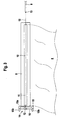
- FIG. 3 shows the components of a device for mounting the awning fabric 6 on the drop bar 8.
- the awning fabric 6 is released from the winding shaft 5. Furthermore, the awning fabric 6 is released from the drop bar 8.
- the piping 9 is pulled out of the drop bar 8 so that the old awning cloth 6 can be released from the drop bar 8 and then removed.
- FIG. 2 shows the components of the device for mounting the new awning fabric 6 on the drop bar. 8
- the new awning fabric 6 has like the old awning fabric 6 at its front edge a seam 11.
- a traction means 12 is retracted, which forms a prefabricated unit with the awning fabric 6.
- the length of the traction means 12 is chosen so that its longitudinal ends project beyond the seam 11.
- the traction means 12 is formed in the present case of a wire. In general, the traction means 12 may also be formed by a string, a rope or the like.
- FIG. 3 shows the awning fabric 6, the seam 11 has been introduced via the groove 10 in the interior of the drop bar 8. Since the traction means 12 is very thin, is the seam 11 with the traction means 12 easily and relatively no effort on the groove 10 in the interior of the drop bar 8 inserted.
- the first longitudinal end of the pulling means 12 protrudes beyond a first open end side of the drop bar 8 and is fixed by means of suitable fixing means 13 at a longitudinal end of the still outside the drop bar 8 arranged piping 9.
- the wire forming the pulling means 12 is wound around the front end of the welt 9.
- 9 notches or holes for receiving the traction means 12 may be provided on the piping.
- 9 hooks, eyes or similar fixing means 13 may be provided for fixing the traction means 12 at the front end of the welt.
- FIG. 4 shows the winding unit 14 in a single representation.
- the winding unit 14 is essentially formed by a winch.
- the take-up unit 14 has a frame 15 consisting of a bottom part 15a and two wall elements 15b.
- the wall elements 15b adjoin opposite edges of the bottom part 15a and protrude perpendicularly from the top thereof.
- the identically formed wall elements 15b form bearings for a shaft 16 as a further component of the take-up unit 14.
- the shaft 16 is rotatably mounted about its longitudinal axis.
- the exposed longitudinal ends of the shaft 16 have slots 16a or similar interfaces for coupling an actuator, by means of which the shaft 16 can be rotated.
- actuators for example, screwdrivers or drills can be used with appropriate essays.
- the bottom part 15a is penetrated by a bore 17.
- the free end of the traction means 12 is first passed through the bore 17 and then secured to the shaft 16.
- the so on the traction means 12 coupled take-up unit 14 then sits, as in FIG. 3 shown on the front side of the drop bar 8.
- the shaft 16 By actuating the actuating element, the shaft 16 is rotated in a rotational direction, whereby the traction means 12 is wound on the shaft 16. As a result, the piping 9 is pulled into the seam 11 of the awning fabric 6, which lies within the drop rod 8.
- the shaft 16 is associated with a rotation lock, not shown, which blocks rotation of the shaft 16 in this direction.
- the rotation lock can consist of mechanical security elements in a known manner.
- the tensile forces exerted on the take-up unit 14 by the welt 9 during the draw in the seam 11 have the advantage that the take-up unit 14, as in FIG. 3 represented, pressed against the front side of the drop bar 8 and is fixed in position there.
- the adapter is formed in this case in the form of a hollow cylindrical sleeve 18.
- the sleeve 18 is reversibly releasably secured by not shown locking or plug-in connections on the underside of the bottom part 15 a of the frame 15.
- the longitudinal end of the traction means 12 is then first passed through the sleeve 18 and then through the bore 17 in the bottom part 15a of the frame 15 to the shaft 16 of the winding unit 14 and then fixed there.
- the sleeve 18 is inserted into the open end side of the drop bar 8, whereby this and the attached winding unit 14 is fixed in position.
- FIG. 6 shows an extension of the embodiment according to FIG. 3 to the effect that prior to attaching the traction means 12 at the piping 9, an insertion aid 19 is threaded onto the traction means 12.
- the insertion aid 19 is formed by a rotationally symmetrical hollow body, which tapers from its open base surface to its front end. Once the traction means 12 is fixed to the fixing means 13 on the piping 9, the insertion aid 19 is attached with its open base surface on the front end.
- the insertion aid 19 forms a tip at the front end of the welt 9, which facilitates insertion into the seam 11 of the awning cloth 6.
Landscapes
- Engineering & Computer Science (AREA)
- Architecture (AREA)
- Civil Engineering (AREA)
- Structural Engineering (AREA)
- Building Awnings And Sunshades (AREA)
Claims (9)
- Toile de store avec dispositif de montage de la toile de store (6) sur une barre de chute (8) d'un store, comprenant une unité préfabriquée constituée de la toile de store (6) et d'un moyen de traction (12) qui est guidé dans un ourlet (11) s'étendant le long d'un bord de la toile de store (6), ainsi que des moyens de fixation (13) au moyen desquels une première extrémité longitudinale du moyen de traction (12), dépassant de l'ourlet (11), peut être fixée à une extrémité longitudinale d'une baguette (9), et une unité d'enroulement (14), qui peut être fixée à la deuxième extrémité longitudinale du moyen de traction (12), dépassant de l'ourlet (11), sachant que, lorsque l'ourlet (11) se trouve dans une rainure (10) de la barre de chute (8), le moyen de traction (12) est enroulé sur l'unité d'enroulement (14) en actionnant celle-ci, de sorte que la baguette (9) est rétractée dans l'ourlet (11).
- Dispositif selon la revendication 1, caractérisé en ce que le moyen de traction (12) est formé par un câble, un cordon ou un fil métallique.
- Dispositif selon la revendication 1 ou 2, caractérisé en ce que l'unité d'enroulement (14) présente un arbre (16), qui est monté à rotation sur un bâti (15) et qui peut être actionné au moyen d'un élément d'actionnement.
- Dispositif selon la revendication 3, caractérisé en ce qu'un blocage en rotation est associé à l'arbre (16), de sorte que ce dernier ne peut être tourné que dans une direction de rotation.
- Dispositif selon la revendication 3 ou 4, caractérisé en ce qu'un adaptateur peut être installé sur le bâti (15) de l'unité d'enroulement (14), adaptateur au moyen duquel l'unité d'enroulement (14) peut être fixée à une extrémité longitudinale de la barre de chute (8).
- Dispositif selon l'une des revendications 1 à 5, caractérisé en ce qu'une aide à l'introduction (19), pour l'introduction de la baguette (9) dans l'ourlet (11), peut être installée à l'extrémité longitudinale de la baguette (9) à laquelle le moyen de traction (12) peut être fixé à l'aide des moyens de fixation (13).
- Procédé de montage d'une toile de store (6) sur une barre de chute (8) d'un store (1), comprenant les étapes suivantes :fourniture d'une unité préfabriquée constituée d'une toile de store (6) et d'un moyen de traction (12) qui est guidé dans un ourlet (11) s'étendant le long d'un bord de la toile de store (6),fixation, à l'aide de moyens de fixation (13), d'une première extrémité longitudinale d'une baguette (9) à une première extrémité longitudinale du moyen de traction (12), dépassant de l'ourlet (11),fixation d'une unité d'enroulement (14) à la deuxième extrémité longitudinale du moyen de traction (12), dépassant de l'ourlet (11),insertion de l'ourlet (11) dans une rainure (10) de la barre de chute (8) et actionnement de l'unité d'enroulement (14), de sorte que le moyen de traction (12) est enroulé sur l'unité d'enroulement (14) et donc que la baguette (9) est rétractée dans l'ourlet (11) situé dans la rainure (10).
- Procédé selon la revendication 7, caractérisé en ce que, par l'actionnement de l'unité d'enroulement (14), celle-ci est fixée en position sur le côté frontal associé de la barre de chute (8).
- Procédé selon la revendication 7 ou 8, caractérisé en ce que l'unité d'enroulement (14) est actionnée manuellement ou mécaniquement.
Priority Applications (3)
| Application Number | Priority Date | Filing Date | Title |
|---|---|---|---|
| AT07013844T ATE450676T1 (de) | 2007-07-14 | 2007-07-14 | Vorrichtung und verfahren zur montage eines markisentuchs an einer fallstange einer markise |
| EP07013844A EP2017398B1 (fr) | 2007-07-14 | 2007-07-14 | Dispositif et procédé destinés au montage d'une toile de store sur une barre de chute d'un store |
| DE502007002194T DE502007002194D1 (de) | 2007-07-14 | 2007-07-14 | Vorrichtung und Verfahren zur Montage eines Markisentuchs an einer Fallstange einer Markise |
Applications Claiming Priority (1)
| Application Number | Priority Date | Filing Date | Title |
|---|---|---|---|
| EP07013844A EP2017398B1 (fr) | 2007-07-14 | 2007-07-14 | Dispositif et procédé destinés au montage d'une toile de store sur une barre de chute d'un store |
Publications (2)
| Publication Number | Publication Date |
|---|---|
| EP2017398A1 EP2017398A1 (fr) | 2009-01-21 |
| EP2017398B1 true EP2017398B1 (fr) | 2009-12-02 |
Family
ID=38698051
Family Applications (1)
| Application Number | Title | Priority Date | Filing Date |
|---|---|---|---|
| EP07013844A Not-in-force EP2017398B1 (fr) | 2007-07-14 | 2007-07-14 | Dispositif et procédé destinés au montage d'une toile de store sur une barre de chute d'un store |
Country Status (3)
| Country | Link |
|---|---|
| EP (1) | EP2017398B1 (fr) |
| AT (1) | ATE450676T1 (fr) |
| DE (1) | DE502007002194D1 (fr) |
Family Cites Families (3)
| Publication number | Priority date | Publication date | Assignee | Title |
|---|---|---|---|---|
| CH261567A (de) * | 1948-01-09 | 1949-05-31 | Meier Jun Hans | Store. |
| US3051446A (en) * | 1959-12-14 | 1962-08-28 | Dutton Lainson Co | Winch construction |
| GB2271366A (en) * | 1992-10-09 | 1994-04-13 | Harold Eastman | Inflatable seal for a e.g.canopy or house extension |
-
2007
- 2007-07-14 EP EP07013844A patent/EP2017398B1/fr not_active Not-in-force
- 2007-07-14 DE DE502007002194T patent/DE502007002194D1/de active Active
- 2007-07-14 AT AT07013844T patent/ATE450676T1/de active
Also Published As
| Publication number | Publication date |
|---|---|
| DE502007002194D1 (de) | 2010-01-14 |
| ATE450676T1 (de) | 2009-12-15 |
| EP2017398A1 (fr) | 2009-01-21 |
Similar Documents
| Publication | Publication Date | Title |
|---|---|---|
| DE102009058416A1 (de) | Schnurführung der Schutzvorrichtung für automatisch auf- und zusammenklappbaren Regenschirm | |
| DE202009017330U1 (de) | Schnurführung der Schutzvorrichtung für automatisch auf- und zuklappbaren Regenschirm | |
| EP0527749B1 (fr) | Marquise a bras articule | |
| DE102005035174B4 (de) | Verkleidung einer, insbesondere ebenen, Fläche mit einem flexiblen Abdeckmaterial, insbesondere Textilmaterial, sowie Verfahren zur Verkleidung | |
| DE9411309U1 (de) | Raffvorhang | |
| EP2017398B1 (fr) | Dispositif et procédé destinés au montage d'une toile de store sur une barre de chute d'un store | |
| EP3293841B1 (fr) | Armature battante de sécurisation des câbles conducteurs | |
| EP3108773B1 (fr) | Élement de cadre pour cadre de serrage | |
| DE9403006U1 (de) | Sonnenschutzvorrichtung | |
| DE19716196C1 (de) | Markise oder Rollo | |
| DE102020007655A1 (de) | Markise und Verfahren zur Montage einer solchen Markise | |
| CH634359A5 (de) | Verbindungsstab zwischen dem schaftrahmen einer webmaschine und dem schaftzughebel der sie steuernden fachbildemaschine. | |
| DE4427297C1 (de) | Fassadenmarkise | |
| DE102021101419A1 (de) | Sonnenschutzanlage mit einem Zugsystem | |
| EP2631412A2 (fr) | Dispositif de montage d'une bande flexible | |
| EP4407209B1 (fr) | Tendeur de câble avec un support de câble et ensemble de tels tendeurs de câble | |
| DE102020006894B3 (de) | Aufwickelbare Beschattungs-, Sicht- oder Wetterschutzplane | |
| EP1614825B1 (fr) | Dispositif d'ombrage | |
| EP1936062B1 (fr) | Guidage d'un profilé d'extension | |
| AT413851B (de) | Bohr- und ankersetzgerät mit bohrstangenzentrierung | |
| DE20200786U1 (de) | Gelenkarmmarkise mit Volantrollo | |
| DE2904884A1 (de) | Gelenkarm-markise | |
| DE2603738A1 (de) | Sonnendach fuer balkone, loggias u.dgl. | |
| DE7804978U1 (de) | Freitragende markise | |
| DE2524947C2 (de) | Markise |
Legal Events
| Date | Code | Title | Description |
|---|---|---|---|
| PUAI | Public reference made under article 153(3) epc to a published international application that has entered the european phase |
Free format text: ORIGINAL CODE: 0009012 |
|
| 17P | Request for examination filed |
Effective date: 20080207 |
|
| AK | Designated contracting states |
Kind code of ref document: A1 Designated state(s): AT BE BG CH CY CZ DE DK EE ES FI FR GB GR HU IE IS IT LI LT LU LV MC MT NL PL PT RO SE SI SK TR |
|
| AX | Request for extension of the european patent |
Extension state: AL BA HR MK RS |
|
| GRAP | Despatch of communication of intention to grant a patent |
Free format text: ORIGINAL CODE: EPIDOSNIGR1 |
|
| GRAS | Grant fee paid |
Free format text: ORIGINAL CODE: EPIDOSNIGR3 |
|
| AKX | Designation fees paid |
Designated state(s): AT BE BG CH CY CZ DE DK EE ES FI FR GB GR HU IE IS IT LI LT LU LV MC MT NL PL PT RO SE SI SK TR |
|
| GRAA | (expected) grant |
Free format text: ORIGINAL CODE: 0009210 |
|
| AK | Designated contracting states |
Kind code of ref document: B1 Designated state(s): AT BE BG CH CY CZ DE DK EE ES FI FR GB GR HU IE IS IT LI LT LU LV MC MT NL PL PT RO SE SI SK TR |
|
| REG | Reference to a national code |
Ref country code: GB Ref legal event code: FG4D Free format text: NOT ENGLISH |
|
| REG | Reference to a national code |
Ref country code: CH Ref legal event code: EP |
|
| REG | Reference to a national code |
Ref country code: IE Ref legal event code: FG4D |
|
| REF | Corresponds to: |
Ref document number: 502007002194 Country of ref document: DE Date of ref document: 20100114 Kind code of ref document: P |
|
| REG | Reference to a national code |
Ref country code: CH Ref legal event code: NV Representative=s name: ROTTMANN, ZIMMERMANN + PARTNER AG |
|
| REG | Reference to a national code |
Ref country code: NL Ref legal event code: VDEP Effective date: 20091202 |
|
| PG25 | Lapsed in a contracting state [announced via postgrant information from national office to epo] |
Ref country code: FI Free format text: LAPSE BECAUSE OF FAILURE TO SUBMIT A TRANSLATION OF THE DESCRIPTION OR TO PAY THE FEE WITHIN THE PRESCRIBED TIME-LIMIT Effective date: 20091202 Ref country code: LT Free format text: LAPSE BECAUSE OF FAILURE TO SUBMIT A TRANSLATION OF THE DESCRIPTION OR TO PAY THE FEE WITHIN THE PRESCRIBED TIME-LIMIT Effective date: 20091202 Ref country code: SE Free format text: LAPSE BECAUSE OF FAILURE TO SUBMIT A TRANSLATION OF THE DESCRIPTION OR TO PAY THE FEE WITHIN THE PRESCRIBED TIME-LIMIT Effective date: 20091202 |
|
| LTIE | Lt: invalidation of european patent or patent extension |
Effective date: 20091202 |
|
| PG25 | Lapsed in a contracting state [announced via postgrant information from national office to epo] |
Ref country code: PL Free format text: LAPSE BECAUSE OF FAILURE TO SUBMIT A TRANSLATION OF THE DESCRIPTION OR TO PAY THE FEE WITHIN THE PRESCRIBED TIME-LIMIT Effective date: 20091202 Ref country code: LV Free format text: LAPSE BECAUSE OF FAILURE TO SUBMIT A TRANSLATION OF THE DESCRIPTION OR TO PAY THE FEE WITHIN THE PRESCRIBED TIME-LIMIT Effective date: 20091202 Ref country code: CY Free format text: LAPSE BECAUSE OF FAILURE TO SUBMIT A TRANSLATION OF THE DESCRIPTION OR TO PAY THE FEE WITHIN THE PRESCRIBED TIME-LIMIT Effective date: 20091202 Ref country code: SI Free format text: LAPSE BECAUSE OF FAILURE TO SUBMIT A TRANSLATION OF THE DESCRIPTION OR TO PAY THE FEE WITHIN THE PRESCRIBED TIME-LIMIT Effective date: 20091202 |
|
| REG | Reference to a national code |
Ref country code: IE Ref legal event code: FD4D |
|
| PG25 | Lapsed in a contracting state [announced via postgrant information from national office to epo] |
Ref country code: BG Free format text: LAPSE BECAUSE OF FAILURE TO SUBMIT A TRANSLATION OF THE DESCRIPTION OR TO PAY THE FEE WITHIN THE PRESCRIBED TIME-LIMIT Effective date: 20100302 Ref country code: RO Free format text: LAPSE BECAUSE OF FAILURE TO SUBMIT A TRANSLATION OF THE DESCRIPTION OR TO PAY THE FEE WITHIN THE PRESCRIBED TIME-LIMIT Effective date: 20091202 Ref country code: IE Free format text: LAPSE BECAUSE OF FAILURE TO SUBMIT A TRANSLATION OF THE DESCRIPTION OR TO PAY THE FEE WITHIN THE PRESCRIBED TIME-LIMIT Effective date: 20091202 Ref country code: EE Free format text: LAPSE BECAUSE OF FAILURE TO SUBMIT A TRANSLATION OF THE DESCRIPTION OR TO PAY THE FEE WITHIN THE PRESCRIBED TIME-LIMIT Effective date: 20091202 Ref country code: PT Free format text: LAPSE BECAUSE OF FAILURE TO SUBMIT A TRANSLATION OF THE DESCRIPTION OR TO PAY THE FEE WITHIN THE PRESCRIBED TIME-LIMIT Effective date: 20100402 Ref country code: ES Free format text: LAPSE BECAUSE OF FAILURE TO SUBMIT A TRANSLATION OF THE DESCRIPTION OR TO PAY THE FEE WITHIN THE PRESCRIBED TIME-LIMIT Effective date: 20100313 Ref country code: IS Free format text: LAPSE BECAUSE OF FAILURE TO SUBMIT A TRANSLATION OF THE DESCRIPTION OR TO PAY THE FEE WITHIN THE PRESCRIBED TIME-LIMIT Effective date: 20100402 Ref country code: NL Free format text: LAPSE BECAUSE OF FAILURE TO SUBMIT A TRANSLATION OF THE DESCRIPTION OR TO PAY THE FEE WITHIN THE PRESCRIBED TIME-LIMIT Effective date: 20091202 |
|
| PG25 | Lapsed in a contracting state [announced via postgrant information from national office to epo] |
Ref country code: SK Free format text: LAPSE BECAUSE OF FAILURE TO SUBMIT A TRANSLATION OF THE DESCRIPTION OR TO PAY THE FEE WITHIN THE PRESCRIBED TIME-LIMIT Effective date: 20091202 Ref country code: CZ Free format text: LAPSE BECAUSE OF FAILURE TO SUBMIT A TRANSLATION OF THE DESCRIPTION OR TO PAY THE FEE WITHIN THE PRESCRIBED TIME-LIMIT Effective date: 20091202 |
|
| PLBE | No opposition filed within time limit |
Free format text: ORIGINAL CODE: 0009261 |
|
| STAA | Information on the status of an ep patent application or granted ep patent |
Free format text: STATUS: NO OPPOSITION FILED WITHIN TIME LIMIT |
|
| PG25 | Lapsed in a contracting state [announced via postgrant information from national office to epo] |
Ref country code: GR Free format text: LAPSE BECAUSE OF FAILURE TO SUBMIT A TRANSLATION OF THE DESCRIPTION OR TO PAY THE FEE WITHIN THE PRESCRIBED TIME-LIMIT Effective date: 20100303 |
|
| 26N | No opposition filed |
Effective date: 20100903 |
|
| BERE | Be: lapsed |
Owner name: IVERA H.-P. RUCK TEXTILHANDEL U. -VERARBEITUNG G. Effective date: 20100731 |
|
| PG25 | Lapsed in a contracting state [announced via postgrant information from national office to epo] |
Ref country code: DK Free format text: LAPSE BECAUSE OF FAILURE TO SUBMIT A TRANSLATION OF THE DESCRIPTION OR TO PAY THE FEE WITHIN THE PRESCRIBED TIME-LIMIT Effective date: 20091202 |
|
| PG25 | Lapsed in a contracting state [announced via postgrant information from national office to epo] |
Ref country code: MC Free format text: LAPSE BECAUSE OF NON-PAYMENT OF DUE FEES Effective date: 20100731 |
|
| PG25 | Lapsed in a contracting state [announced via postgrant information from national office to epo] |
Ref country code: IT Free format text: LAPSE BECAUSE OF FAILURE TO SUBMIT A TRANSLATION OF THE DESCRIPTION OR TO PAY THE FEE WITHIN THE PRESCRIBED TIME-LIMIT Effective date: 20091202 |
|
| REG | Reference to a national code |
Ref country code: FR Ref legal event code: ST Effective date: 20110331 |
|
| PG25 | Lapsed in a contracting state [announced via postgrant information from national office to epo] |
Ref country code: FR Free format text: LAPSE BECAUSE OF NON-PAYMENT OF DUE FEES Effective date: 20100802 |
|
| PG25 | Lapsed in a contracting state [announced via postgrant information from national office to epo] |
Ref country code: BE Free format text: LAPSE BECAUSE OF NON-PAYMENT OF DUE FEES Effective date: 20100731 |
|
| REG | Reference to a national code |
Ref country code: CH Ref legal event code: PFA Owner name: IVERA H.-P. RUECK TEXTILHANDEL U. -VERARBEITUNG G Free format text: IVERA H.-P. RUECK TEXTILHANDEL U. -VERARBEITUNG GMBH#HEINKELSTRASSE 35#73230 KIRCHHEIM/TECK (DE) -TRANSFER TO- IVERA H.-P. RUECK TEXTILHANDEL U. -VERARBEITUNG GMBH#HEINKELSTRASSE 35#73230 KIRCHHEIM/TECK (DE) |
|
| PG25 | Lapsed in a contracting state [announced via postgrant information from national office to epo] |
Ref country code: MT Free format text: LAPSE BECAUSE OF FAILURE TO SUBMIT A TRANSLATION OF THE DESCRIPTION OR TO PAY THE FEE WITHIN THE PRESCRIBED TIME-LIMIT Effective date: 20091202 |
|
| GBPC | Gb: european patent ceased through non-payment of renewal fee |
Effective date: 20110714 |
|
| PG25 | Lapsed in a contracting state [announced via postgrant information from national office to epo] |
Ref country code: GB Free format text: LAPSE BECAUSE OF NON-PAYMENT OF DUE FEES Effective date: 20110714 |
|
| PG25 | Lapsed in a contracting state [announced via postgrant information from national office to epo] |
Ref country code: HU Free format text: LAPSE BECAUSE OF FAILURE TO SUBMIT A TRANSLATION OF THE DESCRIPTION OR TO PAY THE FEE WITHIN THE PRESCRIBED TIME-LIMIT Effective date: 20100603 Ref country code: LU Free format text: LAPSE BECAUSE OF NON-PAYMENT OF DUE FEES Effective date: 20100714 |
|
| PG25 | Lapsed in a contracting state [announced via postgrant information from national office to epo] |
Ref country code: TR Free format text: LAPSE BECAUSE OF FAILURE TO SUBMIT A TRANSLATION OF THE DESCRIPTION OR TO PAY THE FEE WITHIN THE PRESCRIBED TIME-LIMIT Effective date: 20091202 |
|
| PGFP | Annual fee paid to national office [announced via postgrant information from national office to epo] |
Ref country code: DE Payment date: 20130709 Year of fee payment: 7 Ref country code: CH Payment date: 20130719 Year of fee payment: 7 Ref country code: AT Payment date: 20130711 Year of fee payment: 7 |
|
| REG | Reference to a national code |
Ref country code: DE Ref legal event code: R119 Ref document number: 502007002194 Country of ref document: DE |
|
| REG | Reference to a national code |
Ref country code: CH Ref legal event code: PL |
|
| REG | Reference to a national code |
Ref country code: AT Ref legal event code: MM01 Ref document number: 450676 Country of ref document: AT Kind code of ref document: T Effective date: 20140714 |
|
| PG25 | Lapsed in a contracting state [announced via postgrant information from national office to epo] |
Ref country code: LI Free format text: LAPSE BECAUSE OF NON-PAYMENT OF DUE FEES Effective date: 20140731 Ref country code: CH Free format text: LAPSE BECAUSE OF NON-PAYMENT OF DUE FEES Effective date: 20140731 Ref country code: DE Free format text: LAPSE BECAUSE OF NON-PAYMENT OF DUE FEES Effective date: 20150203 |
|
| REG | Reference to a national code |
Ref country code: DE Ref legal event code: R119 Ref document number: 502007002194 Country of ref document: DE Effective date: 20150203 |
|
| PG25 | Lapsed in a contracting state [announced via postgrant information from national office to epo] |
Ref country code: AT Free format text: LAPSE BECAUSE OF NON-PAYMENT OF DUE FEES Effective date: 20140714 |