EP2017442A1 - Adaptive reductant dosing and emission control strategies - Google Patents
Adaptive reductant dosing and emission control strategies Download PDFInfo
- Publication number
- EP2017442A1 EP2017442A1 EP08158025A EP08158025A EP2017442A1 EP 2017442 A1 EP2017442 A1 EP 2017442A1 EP 08158025 A EP08158025 A EP 08158025A EP 08158025 A EP08158025 A EP 08158025A EP 2017442 A1 EP2017442 A1 EP 2017442A1
- Authority
- EP
- European Patent Office
- Prior art keywords
- reductant
- temperature
- dosing
- amount
- distance
- Prior art date
- Legal status (The legal status is an assumption and is not a legal conclusion. Google has not performed a legal analysis and makes no representation as to the accuracy of the status listed.)
- Withdrawn
Links
Images


Classifications
-
- F—MECHANICAL ENGINEERING; LIGHTING; HEATING; WEAPONS; BLASTING
- F01—MACHINES OR ENGINES IN GENERAL; ENGINE PLANTS IN GENERAL; STEAM ENGINES
- F01N—GAS-FLOW SILENCERS OR EXHAUST APPARATUS FOR MACHINES OR ENGINES IN GENERAL; GAS-FLOW SILENCERS OR EXHAUST APPARATUS FOR INTERNAL-COMBUSTION ENGINES
- F01N3/00—Exhaust or silencing apparatus having means for purifying, rendering innocuous, or otherwise treating exhaust
- F01N3/08—Exhaust or silencing apparatus having means for purifying, rendering innocuous, or otherwise treating exhaust for rendering innocuous
- F01N3/10—Exhaust or silencing apparatus having means for purifying, rendering innocuous, or otherwise treating exhaust for rendering innocuous by thermal or catalytic conversion of noxious components of exhaust
- F01N3/18—Exhaust or silencing apparatus having means for purifying, rendering innocuous, or otherwise treating exhaust for rendering innocuous by thermal or catalytic conversion of noxious components of exhaust characterised by methods of operation; Control
- F01N3/20—Exhaust or silencing apparatus having means for purifying, rendering innocuous, or otherwise treating exhaust for rendering innocuous by thermal or catalytic conversion of noxious components of exhaust characterised by methods of operation; Control specially adapted for catalytic conversion
- F01N3/206—Adding periodically or continuously substances to exhaust gases for promoting purification, e.g. catalytic material in liquid form, NOx reducing agents
- F01N3/208—Control of selective catalytic reduction [SCR], e.g. by adjusting the dosing of reducing agent
-
- B—PERFORMING OPERATIONS; TRANSPORTING
- B01—PHYSICAL OR CHEMICAL PROCESSES OR APPARATUS IN GENERAL
- B01D—SEPARATION
- B01D53/00—Separation of gases or vapours; Recovering vapours of volatile solvents from gases; Chemical or biological purification of waste gases, e.g. engine exhaust gases, smoke, fumes, flue gases, aerosols
- B01D53/34—Chemical or biological purification of waste gases
- B01D53/92—Chemical or biological purification of waste gases of engine exhaust gases
- B01D53/94—Chemical or biological purification of waste gases of engine exhaust gases by catalytic processes
- B01D53/9404—Removing only nitrogen compounds
- B01D53/9409—Nitrogen oxides
- B01D53/9431—Processes characterised by a specific device
-
- B—PERFORMING OPERATIONS; TRANSPORTING
- B01—PHYSICAL OR CHEMICAL PROCESSES OR APPARATUS IN GENERAL
- B01D—SEPARATION
- B01D53/00—Separation of gases or vapours; Recovering vapours of volatile solvents from gases; Chemical or biological purification of waste gases, e.g. engine exhaust gases, smoke, fumes, flue gases, aerosols
- B01D53/34—Chemical or biological purification of waste gases
- B01D53/92—Chemical or biological purification of waste gases of engine exhaust gases
- B01D53/94—Chemical or biological purification of waste gases of engine exhaust gases by catalytic processes
- B01D53/9495—Controlling the catalytic process
-
- F—MECHANICAL ENGINEERING; LIGHTING; HEATING; WEAPONS; BLASTING
- F01—MACHINES OR ENGINES IN GENERAL; ENGINE PLANTS IN GENERAL; STEAM ENGINES
- F01N—GAS-FLOW SILENCERS OR EXHAUST APPARATUS FOR MACHINES OR ENGINES IN GENERAL; GAS-FLOW SILENCERS OR EXHAUST APPARATUS FOR INTERNAL-COMBUSTION ENGINES
- F01N11/00—Monitoring or diagnostic devices for exhaust-gas treatment apparatus
-
- B—PERFORMING OPERATIONS; TRANSPORTING
- B01—PHYSICAL OR CHEMICAL PROCESSES OR APPARATUS IN GENERAL
- B01D—SEPARATION
- B01D2251/00—Reactants
- B01D2251/20—Reductants
- B01D2251/206—Ammonium compounds
- B01D2251/2062—Ammonia
-
- B—PERFORMING OPERATIONS; TRANSPORTING
- B01—PHYSICAL OR CHEMICAL PROCESSES OR APPARATUS IN GENERAL
- B01D—SEPARATION
- B01D2251/00—Reactants
- B01D2251/20—Reductants
- B01D2251/206—Ammonium compounds
- B01D2251/2067—Urea
-
- B—PERFORMING OPERATIONS; TRANSPORTING
- B01—PHYSICAL OR CHEMICAL PROCESSES OR APPARATUS IN GENERAL
- B01D—SEPARATION
- B01D2258/00—Sources of waste gases
- B01D2258/01—Engine exhaust gases
- B01D2258/012—Diesel engines and lean burn gasoline engines
-
- F—MECHANICAL ENGINEERING; LIGHTING; HEATING; WEAPONS; BLASTING
- F01—MACHINES OR ENGINES IN GENERAL; ENGINE PLANTS IN GENERAL; STEAM ENGINES
- F01N—GAS-FLOW SILENCERS OR EXHAUST APPARATUS FOR MACHINES OR ENGINES IN GENERAL; GAS-FLOW SILENCERS OR EXHAUST APPARATUS FOR INTERNAL-COMBUSTION ENGINES
- F01N2570/00—Exhaust treating apparatus eliminating, absorbing or adsorbing specific elements or compounds
- F01N2570/14—Nitrogen oxides
-
- F—MECHANICAL ENGINEERING; LIGHTING; HEATING; WEAPONS; BLASTING
- F01—MACHINES OR ENGINES IN GENERAL; ENGINE PLANTS IN GENERAL; STEAM ENGINES
- F01N—GAS-FLOW SILENCERS OR EXHAUST APPARATUS FOR MACHINES OR ENGINES IN GENERAL; GAS-FLOW SILENCERS OR EXHAUST APPARATUS FOR INTERNAL-COMBUSTION ENGINES
- F01N2610/00—Adding substances to exhaust gases
- F01N2610/02—Adding substances to exhaust gases the substance being ammonia or urea
-
- F—MECHANICAL ENGINEERING; LIGHTING; HEATING; WEAPONS; BLASTING
- F01—MACHINES OR ENGINES IN GENERAL; ENGINE PLANTS IN GENERAL; STEAM ENGINES
- F01N—GAS-FLOW SILENCERS OR EXHAUST APPARATUS FOR MACHINES OR ENGINES IN GENERAL; GAS-FLOW SILENCERS OR EXHAUST APPARATUS FOR INTERNAL-COMBUSTION ENGINES
- F01N2900/00—Details of electrical control or of the monitoring of the exhaust gas treating apparatus
- F01N2900/04—Methods of control or diagnosing
- F01N2900/0421—Methods of control or diagnosing using an increment counter when a predetermined event occurs
-
- F—MECHANICAL ENGINEERING; LIGHTING; HEATING; WEAPONS; BLASTING
- F01—MACHINES OR ENGINES IN GENERAL; ENGINE PLANTS IN GENERAL; STEAM ENGINES
- F01N—GAS-FLOW SILENCERS OR EXHAUST APPARATUS FOR MACHINES OR ENGINES IN GENERAL; GAS-FLOW SILENCERS OR EXHAUST APPARATUS FOR INTERNAL-COMBUSTION ENGINES
- F01N2900/00—Details of electrical control or of the monitoring of the exhaust gas treating apparatus
- F01N2900/04—Methods of control or diagnosing
- F01N2900/0422—Methods of control or diagnosing measuring the elapsed time
-
- F—MECHANICAL ENGINEERING; LIGHTING; HEATING; WEAPONS; BLASTING
- F01—MACHINES OR ENGINES IN GENERAL; ENGINE PLANTS IN GENERAL; STEAM ENGINES
- F01N—GAS-FLOW SILENCERS OR EXHAUST APPARATUS FOR MACHINES OR ENGINES IN GENERAL; GAS-FLOW SILENCERS OR EXHAUST APPARATUS FOR INTERNAL-COMBUSTION ENGINES
- F01N2900/00—Details of electrical control or of the monitoring of the exhaust gas treating apparatus
- F01N2900/06—Parameters used for exhaust control or diagnosing
- F01N2900/08—Parameters used for exhaust control or diagnosing said parameters being related to the engine
-
- F—MECHANICAL ENGINEERING; LIGHTING; HEATING; WEAPONS; BLASTING
- F01—MACHINES OR ENGINES IN GENERAL; ENGINE PLANTS IN GENERAL; STEAM ENGINES
- F01N—GAS-FLOW SILENCERS OR EXHAUST APPARATUS FOR MACHINES OR ENGINES IN GENERAL; GAS-FLOW SILENCERS OR EXHAUST APPARATUS FOR INTERNAL-COMBUSTION ENGINES
- F01N2900/00—Details of electrical control or of the monitoring of the exhaust gas treating apparatus
- F01N2900/06—Parameters used for exhaust control or diagnosing
- F01N2900/10—Parameters used for exhaust control or diagnosing said parameters being related to the vehicle or its components
- F01N2900/102—Travelling distance
-
- F—MECHANICAL ENGINEERING; LIGHTING; HEATING; WEAPONS; BLASTING
- F01—MACHINES OR ENGINES IN GENERAL; ENGINE PLANTS IN GENERAL; STEAM ENGINES
- F01N—GAS-FLOW SILENCERS OR EXHAUST APPARATUS FOR MACHINES OR ENGINES IN GENERAL; GAS-FLOW SILENCERS OR EXHAUST APPARATUS FOR INTERNAL-COMBUSTION ENGINES
- F01N2900/00—Details of electrical control or of the monitoring of the exhaust gas treating apparatus
- F01N2900/06—Parameters used for exhaust control or diagnosing
- F01N2900/18—Parameters used for exhaust control or diagnosing said parameters being related to the system for adding a substance into the exhaust
- F01N2900/1806—Properties of reducing agent or dosing system
- F01N2900/1808—Pressure
-
- F—MECHANICAL ENGINEERING; LIGHTING; HEATING; WEAPONS; BLASTING
- F01—MACHINES OR ENGINES IN GENERAL; ENGINE PLANTS IN GENERAL; STEAM ENGINES
- F01N—GAS-FLOW SILENCERS OR EXHAUST APPARATUS FOR MACHINES OR ENGINES IN GENERAL; GAS-FLOW SILENCERS OR EXHAUST APPARATUS FOR INTERNAL-COMBUSTION ENGINES
- F01N2900/00—Details of electrical control or of the monitoring of the exhaust gas treating apparatus
- F01N2900/06—Parameters used for exhaust control or diagnosing
- F01N2900/18—Parameters used for exhaust control or diagnosing said parameters being related to the system for adding a substance into the exhaust
- F01N2900/1806—Properties of reducing agent or dosing system
- F01N2900/1814—Tank level
-
- Y—GENERAL TAGGING OF NEW TECHNOLOGICAL DEVELOPMENTS; GENERAL TAGGING OF CROSS-SECTIONAL TECHNOLOGIES SPANNING OVER SEVERAL SECTIONS OF THE IPC; TECHNICAL SUBJECTS COVERED BY FORMER USPC CROSS-REFERENCE ART COLLECTIONS [XRACs] AND DIGESTS
- Y02—TECHNOLOGIES OR APPLICATIONS FOR MITIGATION OR ADAPTATION AGAINST CLIMATE CHANGE
- Y02A—TECHNOLOGIES FOR ADAPTATION TO CLIMATE CHANGE
- Y02A50/00—TECHNOLOGIES FOR ADAPTATION TO CLIMATE CHANGE in human health protection, e.g. against extreme weather
- Y02A50/20—Air quality improvement or preservation, e.g. vehicle emission control or emission reduction by using catalytic converters
-
- Y—GENERAL TAGGING OF NEW TECHNOLOGICAL DEVELOPMENTS; GENERAL TAGGING OF CROSS-SECTIONAL TECHNOLOGIES SPANNING OVER SEVERAL SECTIONS OF THE IPC; TECHNICAL SUBJECTS COVERED BY FORMER USPC CROSS-REFERENCE ART COLLECTIONS [XRACs] AND DIGESTS
- Y02—TECHNOLOGIES OR APPLICATIONS FOR MITIGATION OR ADAPTATION AGAINST CLIMATE CHANGE
- Y02T—CLIMATE CHANGE MITIGATION TECHNOLOGIES RELATED TO TRANSPORTATION
- Y02T10/00—Road transport of goods or passengers
- Y02T10/10—Internal combustion engine [ICE] based vehicles
- Y02T10/12—Improving ICE efficiencies
-
- Y—GENERAL TAGGING OF NEW TECHNOLOGICAL DEVELOPMENTS; GENERAL TAGGING OF CROSS-SECTIONAL TECHNOLOGIES SPANNING OVER SEVERAL SECTIONS OF THE IPC; TECHNICAL SUBJECTS COVERED BY FORMER USPC CROSS-REFERENCE ART COLLECTIONS [XRACs] AND DIGESTS
- Y02—TECHNOLOGIES OR APPLICATIONS FOR MITIGATION OR ADAPTATION AGAINST CLIMATE CHANGE
- Y02T—CLIMATE CHANGE MITIGATION TECHNOLOGIES RELATED TO TRANSPORTATION
- Y02T10/00—Road transport of goods or passengers
- Y02T10/10—Internal combustion engine [ICE] based vehicles
- Y02T10/40—Engine management systems
Definitions
- the present disclosure relates to an apparatus and method for improving the performance of an exhaust treatment device such as a selective catalytic reduction ( SCR ) system. More particularly, the disclosure relates to adaptive reductant dosing and emission control strategies which may be used in diesel engines. The process may therefore rely upon monitoring of in-tank reductant levels and consideration of variables that may include distance to a reductant refill station, monitoring of reductant consumption level and adjusting reductant dosing to control tailpipe ( NOx ) emissions which may be combined with in-cylinder emission control methods to satisfy emission standards.
- SCR selective catalytic reduction
- diesel engines Internal combustion engines such as those found in cars and trucks may produce combustion byproducts and/or products of incomplete combustion which may be in the engine exhaust and emitted into the environment. Pursuant to emissions regulations, the exhaust may be treated to reduce the concentration of such products and, therefore, reduce pollution.
- spark ignition i.e., gasoline
- compression ignition i.e., diesel
- diesel engines typically employ two-way catalytic converters which may not efficiently reduce nitrogen oxides ( NO x ).
- diesel engines may include a reductant-based selective catalytic reduction ( SCR ) device in order to seek reduction in nitrogen oxide concentrations.
- diesel engines may also include diesel particulate filters ( DPF ) for particulate matter ( PM ) control. Improving the performance of such systems remains an ongoing area of research and development.
- An aspect of the disclosure relates to a method of controlling the reductant dosing level introduced to a SCR device.
- the method may include determining available reductant and determining a distance to a source of reductant. This may then be followed by adjusting a reductant dosing level based upon the available reductant and the distance to a source of reductant.
- Another aspect of the present disclosure relates to a controller amounting to a control unit capable of controlling a reductant dosing level introduced to a selective catalytic reduction catalyst wherein the control unit is capable of determining available reductant and a distance to a source of reductant.
- the control unit may then adjust a reductant dosing level based upon the available reductant and the distance to a source of reductant.
- the control unit may be installed in a vehicle and may also regulate in-cylinder emission control variables to reduce NOx emissions.
- the controller may comprise a control unit capable of controlling a reductant dosing level introduced to a selective catalytic reduction catalyst wherein said control unit is capable of determining available reductant and a distance to a source of reductant; and wherein said control unit is capable of adjusting said reductant dosing level based upon said available reductant and said distance to a source of reductant.
- the control unit may be capable of in-cylinder emission control of one or more of the following: injection timing, amount or temperature of exhaust gas recycling, amount or temperature of air flow, fuel mass, compression ratio, boost pressure or combustion temperature.
- the control unit may be capable of estimating reductant consumption and determining whether or not said available reductant is sufficient to maintain said estimated reductant consumption for said distance to said source of reductant.
- the control unit may be capable of estimating reductant consumption and determining that said available reductant is insufficient to maintain said estimated reductant consumption for said distance to said source of reductant and reduces said reductant dosing level.
- the controller may be capable of adjusting one or more of the following: injection timing, amount or temperature of exhaust gas recycling, amount or temperature of air flow, fuel mass, compression ratio, variable valve actuation timing, boost pressure or combustion temperature, wherein said adjusting is based upon said reduced dosing level.
- the controller may be capable of determining if said available reductant is less than a predetermined level and said controller is capable of adjusting one or more of the following: injection timing, amount or temperature of exhaust gas recycling, amount or temperature of air flow, fuel mass, compression ratio, variable valve actuation timing, boost pressure or combustion temperature at zero reductant dosing.
- the controller may be capable of implementing a by-pass mode with zero reductant dosing and counting the number of times the controller was previously in said by-pass mode with zero reductant dosing.
- the controller may be capable of determining if the number of times the controller was in said by-pass mode has exceeded a previously determined value.
- the controller may be capable of implementing a timer for a given time period and said controller is capable of further adjusting one or more of the following: injection timing, amount or temperature of exhaust gas recycling, amount or temperature of air flow, fuel mass, compression ratio, variable valve actuation timing, boost pressure or combustion temperature for said time period.
- Another aspect of the present disclosure relates to an article comprising a storage medium having stored thereon instruction that when executed by a machine result in the following operations: determining available reductant and determining a distance to a source of reductant. This may then be followed by adjusting a reductant dosing level based upon the available reductant and the distance to a source of reductant.
- the article may comprise a storage medium having stored thereon instruction that when executed by a machine result in the following operations: determining available reductant; determining a distance to a source of reductant; adjusting a reductant dosing level based upon said available reductant and said distance to said source of reductant.
- the instructions that when executed by said machine may result in the following additional operations: adjusting one or more of the following: injection timing, amount or temperature of exhaust gas recycling, amount or temperature of air flow, fuel mass, compression ratio, variable valve actuation timing, boost pressure or combustion temperature.
- the instructions that when executed by said machine may result in the following additional operations: estimating a reductant consumption; determining whether said reductant is sufficient to maintain said reductant consumption for said distance to said source of reductant.
- the instructions that when executed by said machine may result in the following additional operations: estimating a reductant consumption; determining whether said available reductant is sufficient to maintain said estimated reductant consumption for said distance to said source of reductant; and reducing said reductant dosing level when said available reductant is insufficient to maintain said estimated reductant consumption for said distance to said source of reductant.
- the instructions that when executed by said machine may result in the following additional operations: adjusting one or more of the following: injection timing, amount or temperature of exhaust gas recycling, amount or temperature of air flow, fuel mass, compression ratio, variable valve actuation timing, boost pressure or combustion temperature upon said reduced dosing level.
- the instructions that when executed by said machine may result in the following additional operations: determining if said available reductant is less than a predetermined level; and adjusting one or more of the following: injection timing, amount or temperature of exhaust gas recycling, amount or temperature of air flow, fuel mass, compression ratio, variable valve actuation timing, boost pressure or combustion temperature, at zero reductant dosing.
- the instructions that when executed by said machine may result in the following additional operations: implementing a by-pass mode with zero-reductant dosing and counting the number of times previously in said by-pass mode.
- the instructions that when executed by said machine may result in the following additional operations: determining if the number of times previously in said by-pass mode has exceeded a previously determined value.
- selective catalytic reduction may be understood as a process where a reductant may be added to a combustion engine exhaust stream and interact with a catalyst.
- a reductant herein may therefore be understood as any compound (e.g. ammonia) or precursor compound (e.g. urea) that may be relied upon to assist a catalyst to reduce output levels of NOx from a combustion process. More specifically, a reductant such as ammonia may therefore react with the NOx in the exhaust gas to form water and nitrogen.
- urea CO(NH 2 ) 2
- water H 2 O
- a hydrolysis catalyst to yield carbon dioxide ( CO 2 ) and ammonia ( NH 3 ).
- the ammonia in turn may act as more fully described below.
- the selection of urea as an exemplary precursor to provide ammonia and react with NOx in the presence of a catalyst may therefore be illustrated as follows: CO(NH 2 ) 2 + H 2 O ⁇ CO 2 + 2NH 3 2NH 3 + NO + NO 2 ⁇ 2N 2 + 3H 2 O 4NH 3 + 4NO + O 2 ⁇ 4H 2 + 6H 2 O
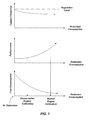
- FIG 1 illustrates the relationship between reductant consumption and vehicle fuel consumption, performance and emissions.
- combustion may be optimized and the engine may employ what may be understood as normal engine calibration.
- NOx emissions may then be relatively high which may then require relatively higher reductant consumption in such normal protocol for SCR to convert NOx to NO 2 .
- reductant may be conserved while maintaining emissions below desired target levels. It may therefore be understood herein that normal engine calibration may consume relatively higher dosage levels of reductant than in conservation engine calibration which may use relative lower dosage levels.
- engine in-cylinder emission control approaches may then be required to maintain emission levels. This may include retarded injection timing (i.e. a delay in the start of fuel injection to reduce combustion temperature), low pressure loop exhaust gas recycling ( EGR ) and/or high pressure loop EGR (which may lower maximum combustion temperature), lower compression ratios, lower temperature combustion, and/or premixed controlled combustion in order to maintain target emission standards. It may also include control of fuel mass, boost pressure, air flow (amount and temperature) and variable valve actuation timing of the intake/exhaust valves and lift. In addition, with respect to EGR, it may include control of the amount and temperature of such exhaust gas recycling.
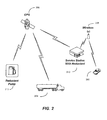
- FIG 2 provides an illustration of an exemplary reductant distribution information system now contemplated by the present disclosure.
- relatively light or heavy duty vehicles 202 and 204 may communicate via GPS 206 or by other wireless systems 208 to determine the location of service stations 210 or other fueling stations 212 where reductant may be distributed.
- the distribution system herein may therefore generate information corresponding to, e.g. the distance between the vehicle and a source for reductant such as an available reductant fill-station.
- An available reductant fill station may be understood as a fill station confirming the availability of reductant through a communication network (e.g. wireless network) for use by a vehicle.
- a communication network e.g. wireless network
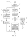
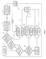
- FIGS. 3A-3B illustrate in scheme 300 how one may intermittently determine a particular reductant dosing mode for engine consumption. Accordingly, at 302 one may start the reductant dosing strategy to initially determine whether a flag should be set indicative of whether or not the reductant in a given vehicle may be above or below some preset limit. At 304 an in-tank monitoring sensor may be triggered for reductant level in a reductant tank 306 and a determination (see below) may be made regarding the reductant level in a given tank. Such determination may be accomplished by, e.g., a fluid level sensor, pressure sensor and/or an optical sensor in communication with the reductant tank.
- a determination may be made as to whether or not the reductant is at a given lower limit.
- Such lower limit may be preprogrammed into the system or be set by the driver. If “yes” at 308 a flag or other indicator may be set at 310 to signify that the reductant is at or below the selected lower limit.
- the on-board diagnostics may be informed that the reductant lower limit flag has been set.
- the system may estimate reductant consumption at 314 at normal reductant dosage levels which may depend upon current driving conditions. This may include average speed, average fuel consumption, etc. Again, as noted above, a normal reductant dosage level or consumption may be understood as a dosage level (e.g.
- the estimated distance the vehicle may travel employing the normal dosage of reductant may be determined. Furthermore, a determination may then be made at 318 as to whether or not normal dosing of reductant may be continued based upon the normal reductant dosing and the distance to a reductant refill station.
- the system may initiate at 320 a monitoring protocol to determine reductant refill station availability.
- the system at 322 may therefore communicate with the reductant distribution information system ( FIG. 2 ) which may then allow the system to determine at 324 the distance to a reductant refill station. For example, GPS or wireless information may be assessed to determine the driving distance to a reductant refill station.
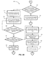
- the system at 330 may clear any conservation reductant flag (explained below) that may have been previously set. If at 318 the system determines that the normal reductant dosing is not available for the given distance (i.e., that the vehicle will run out of reductant,) the system may set a conservation reductant flag at 340. Then, the system at 342 may estimate and select a reduced reductant dosing rate.
- the distance for which the reduced dosing rate is available, prior to running out of reductant may be compared to the distance to a reductant refilling station. If the estimated reduced reductant dosage determined at 342 is too high and the vehicle may run too low or even out of reductant prior to completing the distance to a refilling station at 344, a new reduced reductant dosing rate may be determined at 342. It may therefore be appreciated that conservation reductant dosage herein contemplates a reductant dosage that is less than the above described normal reductant dosing.
- a driver advisory may be issued warning the driver that the vehicle performance may be reduced or at 354 a driver advisory may be issued warning the driver that the vehicle driving distance may need to be reduced due to reduced fuel economy or performance.
- a signal may also be sent to the on-board diagnostics at 356 notifying the on-board diagnostics that the automatic conservation flag is set.
- FIG 4 illustrates how, after a reductant dosing mode is selected ( FIG 3 ) a corresponding engine control mode may be implemented.
- one may start to determine the selection of engine calibration based upon the dosing mode determination and at 404 a determination may be made as to whether or not the reductant low limit flag has been set. If yes, a determination may be made as to whether or not an emergency by-pass of the "reductant-low engine control mode" may have been manually set. If the emergency by-pass was not set at 406 then at 408 the reductant low engine control mode may be implemented. If the emergency by-pass was set at 406 then a counter may be initiated at 410.
- Such counter may keep track of the number of times emergency by-pass mode has been entered into.
- a determination may be made as to whether or not the number of times emergency by-pass mode has been exceeded. If the counter has been exceeded, the reductant low engine control mode may again be implemented at 408. If the counter has not been exceeded at 412, then at 414 the emergency by-pass of the reductant low engine control mode may be set. At 416 the counter may be cleared by an authorized service center.
- the reductant low limit flag has not been set at 404, then at 420 a determination may be made as to whether or not the reduction conservation flag has been set. If such flag has not been set then the normal reductant dose and control mode may be implemented at 422. If such flag has been set a determination may be made at 430 as to whether or not the automatic reductant dosing flag has been set. If yes, at 432, the reductant dosing conservation engine control mode may be implemented. If not, at 434, the driver may be advised of possible mandatory action necessary in view of the available reductant.
- tailpipe emissions and NOx concentration may be relatively low when the normal reductant dosing control mode is selected.
- the relative level of NOx emissions may be low when the reductant dosing conservation mode is set, or when the reductant low engine control mode is set.
- relatively higher NOx emissions may be observed when the emergency by-pass engine control mode is selected.
- FIG 5 illustrates selection of an engine control mode ( FIG. 4 ) and a reductant dosing mode ( FIGS. 3A and 3B ).
- the system may start consideration of an overall engine control strategy determination.
- the system may determine if reductant low-engine control mode has been selected. Such selection may have been made, e.g., at step 408 in FIG. 4 .
- the system may then consider at 504 whether the emergency by-pass of reductant low engine control mode has been selected (see e.g., step 414 in FIG. 4 ).
- a first timer ( t 1 ) may be set for using normal engine calibration without reductant dosing. If t 1 expires a second timer may be set ( t 2 ) at 514 for conservation engine calibration without reductant. If t 2 expires the system goes to 520 which is the engine calibration for low-engine out emissions and no reductant dosing 522. It may be appreciated that during either t 1 or t 2 there may be relatively high tailpipe emissions as shown at 518.
- the engine may then reduce tailpipe emissions, such that relatively low tailpipe emissions may be produced at 524.
- engine calibrations may include, as noted above, retarded injection timing (i.e. a delay in the start of fuel injection to reduce combustion temperature), low pressure loop exhaust gas recycling (EGR) and or high pressure loop EGR (which may lower maximum combustion temperature), lower compression ratios, lower temperature combustion, and/or premixed controlled combustion. It may also include control of fuel mass, boost pressure, air flow (amount and temperature), variable valve actuation timing and lift, and control of the amount and temperature of recycled exhaust gas.
- retarded injection timing i.e. a delay in the start of fuel injection to reduce combustion temperature
- EGR low pressure loop exhaust gas recycling
- high pressure loop EGR which may lower maximum combustion temperature
- lower compression ratios lower temperature combustion
- premixed controlled combustion may also include control of fuel mass, boost pressure, air flow (amount and temperature), variable valve actuation timing and lift, and control of the amount and temperature of recycled exhaust gas.
- reductant-low engine control mode is not selected at 506 then a determination may be made as to whether reductant dosing conservation engine control mode has been selected at 508. Such selection may have been made, for example, at step 432 in FIG 4 . If reductant doing conservation engine control mode has been selected at 508, then the engine may be operated under the calibration to provide reductant conservation at 530 and reductant dosing may be set for conservation at 532 which may produce relatively low tailpipe emissions at 524.
- normal reductant dosing conservation engine control mode may be set. Such selection may have been previously made at 422 of FIG 4 . Accordingly, in such mode, normal engine calibration may be implemented at 540 and normal reductant dosing may be provided at 542 producing relatively low tailpipe emissions at 524.
- FIG 6 illustrates an exemplary overview of the vehicle control system for implementing the above control scheme.
- a vehicle 600 may include a controller 602 wherein the controller 602 may receive data from wireless communications 620, GPS 622 as well as driver input 624.
- the engine controller may also received data from a sensor 604 in communication with a reductant tank 606, indicating the level of reductant in the tank.
- the controller may assess information obtained from the various inputs, such as the driving distance to a reductant refilling station and/or level of reductant in the tank which may be supplied from the GPS 622 and/or wireless tower 620 and/or from manual input.
- the controller may therefore communicate with the engine 610 and a reductant dosing valve 612. Exhaust 614 from the engine may be directed to a SCR 616.
- Reductant 618 may be added to the exhaust 614, once the exhaust enters the SCR or just prior to entering the SCR. Once the exhaust is treated with the reductant, as described above, the treated exhaust may be emitted from the tailpipe 618.
- the controller may then implement any of the protocols outlined above in FIGS. 3-5 to control the engine 614 and dosing of the reductant 618 via the reductant dosing valve 612.
- the controller 602 may also amount to an after-market controller that may be employed in a given vehicle engine to improve performance of a given SCR system. Accordingly it is contemplated herein that the controller herein may provide the in-cylinder control noted above and/or coordinate with an existing vehicle engine in-cylinder control system.
- the functionality described herein for the embodiments of the present invention may be implemented by using hardware, software, or a combination of hardware and software, either within the engine combustion controller or outside the engine combustion controller, as desired. If implemented by software, a processor and a machine readable medium are required.
- the processor may be of any type of processor capable of providing the speed and functionality required by the embodiments of the invention.
- Machine-readable memory includes any media capable of storing instructions adapted to be executed by a processor.
- ROM read-only memory
- RAM random-access memory
- PROM programmable ROM
- EPROM erasable programmable ROM
- EEPROM electronically erasable programmable ROM
- DRAM dynamic RAM
- magnetic disk e.g., floppy disk and hard drive
- optical disk e.g. CD-ROM
- ROM read-only memory
- RAM random-access memory
- PROM programmable ROM
- EPROM erasable programmable ROM
- EEPROM electronically erasable programmable ROM
- DRAM dynamic RAM
- magnetic disk e.g., floppy disk and hard drive
- optical disk e.g. CD-ROM
Landscapes
- Engineering & Computer Science (AREA)
- Chemical & Material Sciences (AREA)
- Chemical Kinetics & Catalysis (AREA)
- Combustion & Propulsion (AREA)
- Health & Medical Sciences (AREA)
- Biomedical Technology (AREA)
- Mechanical Engineering (AREA)
- General Engineering & Computer Science (AREA)
- Environmental & Geological Engineering (AREA)
- Analytical Chemistry (AREA)
- General Chemical & Material Sciences (AREA)
- Oil, Petroleum & Natural Gas (AREA)
- Toxicology (AREA)
- Exhaust Gas After Treatment (AREA)
- Combined Controls Of Internal Combustion Engines (AREA)
- Exhaust Gas Treatment By Means Of Catalyst (AREA)
Abstract
Description
- The present disclosure relates to an apparatus and method for improving the performance of an exhaust treatment device such as a selective catalytic reduction (SCR) system. More particularly, the disclosure relates to adaptive reductant dosing and emission control strategies which may be used in diesel engines. The process may therefore rely upon monitoring of in-tank reductant levels and consideration of variables that may include distance to a reductant refill station, monitoring of reductant consumption level and adjusting reductant dosing to control tailpipe (NOx) emissions which may be combined with in-cylinder emission control methods to satisfy emission standards.
- Internal combustion engines such as those found in cars and trucks may produce combustion byproducts and/or products of incomplete combustion which may be in the engine exhaust and emitted into the environment. Pursuant to emissions regulations, the exhaust may be treated to reduce the concentration of such products and, therefore, reduce pollution. Although spark ignition (i.e., gasoline) engines may use three-way catalytic converters to satisfy emissions regulations, compression ignition (i.e., diesel) engines typically employ two-way catalytic converters which may not efficiently reduce nitrogen oxides (NOx ). Accordingly, diesel engines may include a reductant-based selective catalytic reduction (SCR) device in order to seek reduction in nitrogen oxide concentrations. In addition, diesel engines may also include diesel particulate filters (DPF) for particulate matter (PM) control. Improving the performance of such systems remains an ongoing area of research and development.
- An aspect of the disclosure relates to a method of controlling the reductant dosing level introduced to a SCR device. The method may include determining available reductant and determining a distance to a source of reductant. This may then be followed by adjusting a reductant dosing level based upon the available reductant and the distance to a source of reductant.
- Another aspect of the present disclosure relates to a controller amounting to a control unit capable of controlling a reductant dosing level introduced to a selective catalytic reduction catalyst wherein the control unit is capable of determining available reductant and a distance to a source of reductant. The control unit may then adjust a reductant dosing level based upon the available reductant and the distance to a source of reductant. The control unit may be installed in a vehicle and may also regulate in-cylinder emission control variables to reduce NOx emissions.
The controller may comprise a control unit capable of controlling a reductant dosing level introduced to a selective catalytic reduction catalyst wherein said control unit is capable of determining available reductant and a distance to a source of reductant; and wherein said control unit is capable of adjusting said reductant dosing level based upon said available reductant and said distance to a source of reductant.
The control unit may be capable of in-cylinder emission control of one or more of the following: injection timing, amount or temperature of exhaust gas recycling, amount or temperature of air flow, fuel mass, compression ratio, boost pressure or combustion temperature.
The control unit may be capable of estimating reductant consumption and determining whether or not said available reductant is sufficient to maintain said estimated reductant consumption for said distance to said source of reductant.
The control unit may be capable of estimating reductant consumption and determining that said available reductant is insufficient to maintain said estimated reductant consumption for said distance to said source of reductant and reduces said reductant dosing level.
The controller may be capable of adjusting one or more of the following: injection timing, amount or temperature of exhaust gas recycling, amount or temperature of air flow, fuel mass, compression ratio, variable valve actuation timing, boost pressure or combustion temperature, wherein said adjusting is based upon said reduced dosing level.
The controller may be capable of determining if said available reductant is less than a predetermined level and said controller is capable of adjusting one or more of the following: injection timing, amount or temperature of exhaust gas recycling, amount or temperature of air flow, fuel mass, compression ratio, variable valve actuation timing, boost pressure or combustion temperature at zero reductant dosing.
The controller may be capable of implementing a by-pass mode with zero reductant dosing and counting the number of times the controller was previously in said by-pass mode with zero reductant dosing.
The controller may be capable of determining if the number of times the controller was in said by-pass mode has exceeded a previously determined value.
The controller may be capable of implementing a timer for a given time period and said controller is capable of further adjusting one or more of the following: injection timing, amount or temperature of exhaust gas recycling, amount or temperature of air flow, fuel mass, compression ratio, variable valve actuation timing, boost pressure or combustion temperature for said time period. - Another aspect of the present disclosure relates to an article comprising a storage medium having stored thereon instruction that when executed by a machine result in the following operations: determining available reductant and determining a distance to a source of reductant. This may then be followed by adjusting a reductant dosing level based upon the available reductant and the distance to a source of reductant.
The article may comprise a storage medium having stored thereon instruction that when executed by a machine result in the following operations: determining available reductant; determining a distance to a source of reductant; adjusting a reductant dosing level based upon said available reductant and said distance to said source of reductant.
The instructions that when executed by said machine may result in the following additional operations: adjusting one or more of the following: injection timing, amount or temperature of exhaust gas recycling, amount or temperature of air flow, fuel mass, compression ratio, variable valve actuation timing, boost pressure or combustion temperature.
The instructions that when executed by said machine may result in the following additional operations: estimating a reductant consumption; determining whether said reductant is sufficient to maintain said reductant consumption for said distance to said source of reductant.
The instructions that when executed by said machine may result in the following additional operations: estimating a reductant consumption; determining whether said available reductant is sufficient to maintain said estimated reductant consumption for said distance to said source of reductant; and reducing said reductant dosing level when said available reductant is insufficient to maintain said estimated reductant consumption for said distance to said source of reductant.
The instructions that when executed by said machine may result in the following additional operations: adjusting one or more of the following: injection timing, amount or temperature of exhaust gas recycling, amount or temperature of air flow, fuel mass, compression ratio, variable valve actuation timing, boost pressure or combustion temperature upon said reduced dosing level.
The instructions that when executed by said machine may result in the following additional operations: determining if said available reductant is less than a predetermined level; and adjusting one or more of the following: injection timing, amount or temperature of exhaust gas recycling, amount or temperature of air flow, fuel mass, compression ratio, variable valve actuation timing, boost pressure or combustion temperature, at zero reductant dosing.
The instructions that when executed by said machine may result in the following additional operations: implementing a by-pass mode with zero-reductant dosing and counting the number of times previously in said by-pass mode.
The instructions that when executed by said machine may result in the following additional operations: determining if the number of times previously in said by-pass mode has exceeded a previously determined value.
The instructions that when executed by said machine may result in the following additional operations initiating a timer for a given time period; and further adjusting one or more of the following: injection timing, amount or temperature of exhaust gas recycling, amount or temperature of air flow, fuel mass, compression ratio, variable valve actuation timing, boost pressure or combustion temperature, at zero reductant dosing for said period. - Features and advantages of the claimed subject matter will be apparent from the following detailed description of embodiments consistent therewith, which description should be considered with reference to the accompanying drawings, wherein:
-
FIG. 1 illustrates the relationship between reductant consumption and vehicle fuel consumption, performance and emissions. -
FIG. 2 illustrates an exemplary wireless communication network as between relatively light and heavy-duty vehicles and a reductant service station which system may monitor distance to reductant fill-up and availability of reductant for a given vehicle. -
FIGS. 3A and3B provides a flow-chart illustrating the determination of a reductant dosing mode. -
FIG. 4 illustrates selection of a corresponding engine control mode according to the reductant dosage mode as illustrated inFIG. 3 . -
FIG. 5 illustrates selection of an engine control mode (FIG. 4 ) and a reductant dosing mode (FIGS. 3A and3B ). -
FIG. 6 illustrates an exemplary overview of the exemplary vehicle control system disclosed herein. -
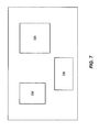
FIG. 7 illustrates the engine combustion controller herein as including a processor, machine readable media and a user interface. - Although the following detailed description will proceed with reference being made to illustrative embodiments, many alternatives, modifications, and variations thereof will be apparent to those skilled in the art.
- As alluded to above, selective catalytic reduction (SCR) may be understood as a process where a reductant may be added to a combustion engine exhaust stream and interact with a catalyst. A reductant herein may therefore be understood as any compound (e.g. ammonia) or precursor compound (e.g. urea) that may be relied upon to assist a catalyst to reduce output levels of NOx from a combustion process. More specifically, a reductant such as ammonia may therefore react with the NOx in the exhaust gas to form water and nitrogen. In the case of urea (CO(NH2)2), which is one example of a precursor compound, it may react with water (H2O) in the presence of a hydrolysis catalyst to yield carbon dioxide (CO2 ) and ammonia (NH3 ). The ammonia in turn may act as more fully described below. The selection of urea as an exemplary precursor to provide ammonia and react with NOx in the presence of a catalyst may therefore be illustrated as follows:
CO(NH2)2 + H2O → CO2 + 2NH3
2NH3 + NO + NO2 → 2N2 + 3H2O
4NH3 + 4NO + O2 → 4H2 + 6H2O
- Attention is therefore directed to
FIG 1 which illustrates the relationship between reductant consumption and vehicle fuel consumption, performance and emissions. As may now be appreciated, when the engine is configured for higher fuel economy and relative strong performance, combustion may be optimized and the engine may employ what may be understood as normal engine calibration. However, NOx emissions may then be relatively high which may then require relatively higher reductant consumption in such normal protocol for SCR to convert NOx to NO2. Under conservation engine calibration, and although there may be relatively less efficient combustion and lower fuel economy, reductant may be conserved while maintaining emissions below desired target levels. It may therefore be understood herein that normal engine calibration may consume relatively higher dosage levels of reductant than in conservation engine calibration which may use relative lower dosage levels. - As may also be appreciated, under those circumstances where there may be no precursor such as urea, engine in-cylinder emission control approaches may then be required to maintain emission levels. This may include retarded injection timing (i.e. a delay in the start of fuel injection to reduce combustion temperature), low pressure loop exhaust gas recycling (EGR) and/or high pressure loop EGR (which may lower maximum combustion temperature), lower compression ratios, lower temperature combustion, and/or premixed controlled combustion in order to maintain target emission standards. It may also include control of fuel mass, boost pressure, air flow (amount and temperature) and variable valve actuation timing of the intake/exhaust valves and lift. In addition, with respect to EGR, it may include control of the amount and temperature of such exhaust gas recycling. However, under these circumstances, where the SCR NOx catalyst is not employed, fuel economy and performance may be significantly compromised and may create excess particulate (e.g. soot). It may therefore be appreciated that the availability of reductant may be an important variable in connection with optimizing exhaust treatment.
- Attention is therefore directed to
FIG 2 which provides an illustration of an exemplary reductant distribution information system now contemplated by the present disclosure. As may be appreciated, relatively light orheavy duty vehicles GPS 206 or byother wireless systems 208 to determine the location ofservice stations 210 or other fuelingstations 212 where reductant may be distributed. The distribution system herein may therefore generate information corresponding to, e.g. the distance between the vehicle and a source for reductant such as an available reductant fill-station. An available reductant fill station may be understood as a fill station confirming the availability of reductant through a communication network (e.g. wireless network) for use by a vehicle. - Attention is next directed to
FIGS. 3A-3B which illustrate inscheme 300 how one may intermittently determine a particular reductant dosing mode for engine consumption. Accordingly, at 302 one may start the reductant dosing strategy to initially determine whether a flag should be set indicative of whether or not the reductant in a given vehicle may be above or below some preset limit. At 304 an in-tank monitoring sensor may be triggered for reductant level in areductant tank 306 and a determination (see below) may be made regarding the reductant level in a given tank. Such determination may be accomplished by, e.g., a fluid level sensor, pressure sensor and/or an optical sensor in communication with the reductant tank. - Accordingly, at 308, a determination may be made as to whether or not the reductant is at a given lower limit. Such lower limit may be preprogrammed into the system or be set by the driver. If "yes" at 308 a flag or other indicator may be set at 310 to signify that the reductant is at or below the selected lower limit. At 312 the on-board diagnostics may be informed that the reductant lower limit flag has been set. If "no" at 308 the system may estimate reductant consumption at 314 at normal reductant dosage levels which may depend upon current driving conditions. This may include average speed, average fuel consumption, etc. Again, as noted above, a normal reductant dosage level or consumption may be understood as a dosage level (e.g. grams/unit of time) that may be provided to reduce the relatively high NOx levels during normal engine calibration. Accordingly at 316, the estimated distance the vehicle may travel employing the normal dosage of reductant may be determined. Furthermore, a determination may then be made at 318 as to whether or not normal dosing of reductant may be continued based upon the normal reductant dosing and the distance to a reductant refill station.
- As noted above, at the time that the above referenced reductant dosing strategy is implemented, the system may initiate at 320 a monitoring protocol to determine reductant refill station availability. The system at 322 may therefore communicate with the reductant distribution information system (
FIG. 2 ) which may then allow the system to determine at 324 the distance to a reductant refill station. For example, GPS or wireless information may be assessed to determine the driving distance to a reductant refill station. - Accordingly, at 318, if the system determines that reductant is available under normal dosing conditions through the distance to a reductant refill station, (i.e., that there will be sufficient reductant in the tank to adequately process NOx at some regulatory level over a given distance) the system at 330 may clear any conservation reductant flag (explained below) that may have been previously set. If at 318 the system determines that the normal reductant dosing is not available for the given distance (i.e., that the vehicle will run out of reductant,) the system may set a conservation reductant flag at 340. Then, the system at 342 may estimate and select a reduced reductant dosing rate. At 344, the distance for which the reduced dosing rate is available, prior to running out of reductant, may be compared to the distance to a reductant refilling station. If the estimated reduced reductant dosage determined at 342 is too high and the vehicle may run too low or even out of reductant prior to completing the distance to a refilling station at 344, a new reduced reductant dosing rate may be determined at 342. It may therefore be appreciated that conservation reductant dosage herein contemplates a reductant dosage that is less than the above described normal reductant dosing.
- If the estimated reduced reductant dosing rate provides a sufficient distance to a refilling station at 344, then at 346 a determination may be made as to whether the driver has selected or activated an automatic reduced reductant conservation mode. If automatic reductant conservation mode has not been selected at 346, then at 348 the driver may be advised of possible mandatory action. If automatic reductant conservation mode has been selected at 346 then at 350 the automatic reductant conservation flag may be set. At 352 a driver advisory may be issued warning the driver that the vehicle performance may be reduced or at 354 a driver advisory may be issued warning the driver that the vehicle driving distance may need to be reduced due to reduced fuel economy or performance. A signal may also be sent to the on-board diagnostics at 356 notifying the on-board diagnostics that the automatic conservation flag is set.
- Attention is next directed to
FIG 4 which illustrates how, after a reductant dosing mode is selected (FIG 3 ) a corresponding engine control mode may be implemented. Specifically, at 402 one may start to determine the selection of engine calibration based upon the dosing mode determination and at 404 a determination may be made as to whether or not the reductant low limit flag has been set. If yes, a determination may be made as to whether or not an emergency by-pass of the "reductant-low engine control mode" may have been manually set. If the emergency by-pass was not set at 406 then at 408 the reductant low engine control mode may be implemented. If the emergency by-pass was set at 406 then a counter may be initiated at 410. Such counter may keep track of the number of times emergency by-pass mode has been entered into. At 412 a determination may be made as to whether or not the number of times emergency by-pass mode has been exceeded. If the counter has been exceeded, the reductant low engine control mode may again be implemented at 408. If the counter has not been exceeded at 412, then at 414 the emergency by-pass of the reductant low engine control mode may be set. At 416 the counter may be cleared by an authorized service center. - If the reductant low limit flag has not been set at 404, then at 420 a determination may be made as to whether or not the reduction conservation flag has been set. If such flag has not been set then the normal reductant dose and control mode may be implemented at 422. If such flag has been set a determination may be made at 430 as to whether or not the automatic reductant dosing flag has been set. If yes, at 432, the reductant dosing conservation engine control mode may be implemented. If not, at 434, the driver may be advised of possible mandatory action necessary in view of the available reductant.
- It may therefore be appreciated in
FIG 4 that tailpipe emissions and NOx concentration may be relatively low when the normal reductant dosing control mode is selected. Similarly, the relative level of NOx emissions may be low when the reductant dosing conservation mode is set, or when the reductant low engine control mode is set. However, relatively higher NOx emissions may be observed when the emergency by-pass engine control mode is selected. -
FIG 5 illustrates selection of an engine control mode (FIG. 4 ) and a reductant dosing mode (FIGS. 3A and3B ). At 502 the system may start consideration of an overall engine control strategy determination. At 506 the system may determine if reductant low-engine control mode has been selected. Such selection may have been made, e.g., atstep 408 inFIG. 4 . The system may then consider at 504 whether the emergency by-pass of reductant low engine control mode has been selected (see e.g.,step 414 inFIG. 4 ). If the mode was selected at 504 and the maximum number of times emergency by-pass mode may be entered has not been exceeded at 511 (as determined by referencing a counter) then at 512 a first timer (t1 ) may be set for using normal engine calibration without reductant dosing. If t1 expires a second timer may be set (t2 ) at 514 for conservation engine calibration without reductant. If t2 expires the system goes to 520 which is the engine calibration for low-engine out emissions and noreductant dosing 522. It may be appreciated that during either t1 or t2 there may be relatively high tailpipe emissions as shown at 518. In such a manner, i.e., operating the engine under low engine-out emission calibration at 520, the engine may then reduce tailpipe emissions, such that relatively low tailpipe emissions may be produced at 524. Such engine calibrations may include, as noted above, retarded injection timing (i.e. a delay in the start of fuel injection to reduce combustion temperature), low pressure loop exhaust gas recycling (EGR) and or high pressure loop EGR (which may lower maximum combustion temperature), lower compression ratios, lower temperature combustion, and/or premixed controlled combustion. It may also include control of fuel mass, boost pressure, air flow (amount and temperature), variable valve actuation timing and lift, and control of the amount and temperature of recycled exhaust gas. - If reductant-low engine control mode is not selected at 506 then a determination may be made as to whether reductant dosing conservation engine control mode has been selected at 508. Such selection may have been made, for example, at
step 432 inFIG 4 . If reductant doing conservation engine control mode has been selected at 508, then the engine may be operated under the calibration to provide reductant conservation at 530 and reductant dosing may be set for conservation at 532 which may produce relatively low tailpipe emissions at 524. - If reductant dosing conservation engine control mode has not been selected at 508 then at 510 normal reductant dosing mode may be set. Such selection may have been previously made at 422 of
FIG 4 . Accordingly, in such mode, normal engine calibration may be implemented at 540 and normal reductant dosing may be provided at 542 producing relatively low tailpipe emissions at 524. -
FIG 6 illustrates an exemplary overview of the vehicle control system for implementing the above control scheme. Avehicle 600 may include acontroller 602 wherein thecontroller 602 may receive data fromwireless communications 620,GPS 622 as well asdriver input 624. The engine controller may also received data from asensor 604 in communication with areductant tank 606, indicating the level of reductant in the tank. The controller may assess information obtained from the various inputs, such as the driving distance to a reductant refilling station and/or level of reductant in the tank which may be supplied from theGPS 622 and/orwireless tower 620 and/or from manual input. The controller may therefore communicate with theengine 610 and areductant dosing valve 612. Exhaust 614 from the engine may be directed to aSCR 616.Reductant 618 may be added to theexhaust 614, once the exhaust enters the SCR or just prior to entering the SCR. Once the exhaust is treated with the reductant, as described above, the treated exhaust may be emitted from thetailpipe 618. The controller may then implement any of the protocols outlined above inFIGS. 3-5 to control theengine 614 and dosing of thereductant 618 via thereductant dosing valve 612. Thecontroller 602 may also amount to an after-market controller that may be employed in a given vehicle engine to improve performance of a given SCR system. Accordingly it is contemplated herein that the controller herein may provide the in-cylinder control noted above and/or coordinate with an existing vehicle engine in-cylinder control system. - It should also be appreciated that the functionality described herein for the embodiments of the present invention may be implemented by using hardware, software, or a combination of hardware and software, either within the engine combustion controller or outside the engine combustion controller, as desired. If implemented by software, a processor and a machine readable medium are required. The processor may be of any type of processor capable of providing the speed and functionality required by the embodiments of the invention. Machine-readable memory includes any media capable of storing instructions adapted to be executed by a processor. Some examples of such memory include, but are not limited to, read-only memory (ROM), random-access memory (RAM), programmable ROM (PROM), erasable programmable ROM (EPROM), electronically erasable programmable ROM (EEPROM), dynamic RAM (DRAM), magnetic disk (e.g., floppy disk and hard drive), optical disk (e.g. CD-ROM), and any other device that can store digital information. The instructions may be stored on medium in either a compressed and/or encrypted format. Accordingly, in the broad context of the present invention, and with attention to
FIG. 7 , the engine combustion controller may contain a processor (710) and machine readable media (720) and user interface (730). Various features, aspects, and embodiments have been described herein. The features, aspects, and embodiments are susceptible to combination with one another as well as to variation and modification, as will be understood by those having skill in the art. The present disclosure should, therefore, be considered to encompass such combinations, variations, and modifications.
Claims (9)
- A method of controlling reductant dosing level introduced to a selective catalytic reduction device, for implementation by a vehicle controller, comprising:determining available reductant;determining a distance to a source of reductant;adjusting a reductant dosing level based upon said available reductant and said distance to a source of reductant.
- The method of claim 1 further comprising:adjusting one or more of the following: injection timing, amount or temperature of exhaust gas recycling, amount or temperature of air flow, fuel mass, compression ratio, variable valve actuation timing, boost pressure or combustion temperature.
- The method of claim 1 or claim 2 further comprising:estimating a reductant consumption;determining whether said reductant is sufficient to maintain said reductant consumption for said distance to said source of reductant.
- The method of claim 1, claim 2 or claim 3 further comprising:estimating a reductant consumption;determining whether said available reductant is sufficient to maintain said estimated reductant consumption for said distance to said source of reductant; andreducing said reductant dosing level when said available reductant is insufficient to maintain said estimated reductant consumption for said distance to said source of reductant.
- The method of any preceding claim further comprising adjusting one or more of the following: injection timing, amount or temperature of exhaust gas recycling, amount or temperature of air flow, fuel mass, compression ratio, variable valve actuation timing, boost pressure or combustion temperature, based upon said reduced dosing level.
- The method of any preceding claim further comprising:determining if said available reductant is less than a predetermined level; andadjusting one or more of the following: injection timing, amount or temperature of exhaust gas recycling, amount or temperature of air flow, fuel mass, compression ratio, variable valve actuation timing, boost pressure or combustion temperature, at zero reductant dosing.
- The method of any preceding claim further comprising:implementing a by-pass mode with zero-reductant dosing and counting the number of times previously in said by-pass mode.
- The method of claim 7 comprising determining if the number of times previously in said by-pass mode has exceeded a previously determined value.
- The method of any preceding claim further comprising:initiating a timer for a given time period; andfurther adjusting one or more of the following: injection timing, amount or temperature of exhaust gas recycling, amount or temperature of air flow, fuel mass, compression ratio, variable valve actuation timing, boost pressure or combustion temperature, at zero reductant dosing for said period.
Applications Claiming Priority (1)
| Application Number | Priority Date | Filing Date | Title |
|---|---|---|---|
| US11/761,205 US7991533B2 (en) | 2007-06-11 | 2007-06-11 | Adaptive reductant dosing and emission control strategies |
Publications (1)
| Publication Number | Publication Date |
|---|---|
| EP2017442A1 true EP2017442A1 (en) | 2009-01-21 |
Family
ID=39740115
Family Applications (1)
| Application Number | Title | Priority Date | Filing Date |
|---|---|---|---|
| EP08158025A Withdrawn EP2017442A1 (en) | 2007-06-11 | 2008-06-11 | Adaptive reductant dosing and emission control strategies |
Country Status (3)
| Country | Link |
|---|---|
| US (1) | US7991533B2 (en) |
| EP (1) | EP2017442A1 (en) |
| JP (1) | JP2009008074A (en) |
Cited By (2)
| Publication number | Priority date | Publication date | Assignee | Title |
|---|---|---|---|---|
| FR2961558A1 (en) * | 2010-06-22 | 2011-12-23 | Peugeot Citroen Automobiles Sa | METHOD FOR ADAPTING THE ADJUSTMENTS OF AN ENGINE ON THE CONSUMPTION OF NITROGEN OXIDE REDUCING AGENT |
| FR3047521A1 (en) * | 2016-02-05 | 2017-08-11 | Renault Sas | METHOD FOR CONTROLLING A MOTORIZATION DEVICE AND ASSOCIATED MOTORIZATION DEVICE |
Families Citing this family (22)
| Publication number | Priority date | Publication date | Assignee | Title |
|---|---|---|---|---|
| US9103248B2 (en) * | 2006-01-19 | 2015-08-11 | Cummins Inc. | Method and system for optimizing fuel and reductant consumption |
| JP4759496B2 (en) * | 2006-11-24 | 2011-08-31 | 本田技研工業株式会社 | Exhaust gas purification device for internal combustion engine |
| US7832200B2 (en) * | 2008-04-23 | 2010-11-16 | Caterpillar Inc | Exhaust system implementing feedforward and feedback control |
| US9194273B2 (en) * | 2008-10-31 | 2015-11-24 | Cummins Inc. | Apparatus, system, and method for aftertreatment control and diagnostics |
| DE102009000334A1 (en) * | 2009-01-20 | 2010-07-22 | Robert Bosch Gmbh | Internal combustion engine operating method for motor vehicle, involves detecting and/or evaluating signals of one filling level sensor or signals of filling level sensors by navigation unit |
| DE102009027375A1 (en) * | 2009-07-01 | 2011-03-10 | Robert Bosch Gmbh | Diagnostic method for making a diagnosis of a system |
| JP5495293B2 (en) | 2009-07-06 | 2014-05-21 | 株式会社日立産機システム | Compressor |
| US9797288B2 (en) * | 2010-07-08 | 2017-10-24 | GM Global Technology Operations LLC | Method of operating a vehicle under frozen diesel emission fluid conditions |
| JP2013534291A (en) * | 2010-08-18 | 2013-09-02 | エミテック ゲゼルシヤフト フユア エミツシオンステクノロギー ミツト ベシユレンクテル ハフツング | Operation method of exhaust gas treatment device |
| US8789358B2 (en) * | 2010-11-12 | 2014-07-29 | GM Global Technology Operations LLC | Selective catalytic reduction catalyst ammonia storage control systems and methods |
| DE102010056399A1 (en) * | 2010-12-28 | 2012-06-28 | GM Global Technology Operations LLC | Motor vehicle with an exhaust aftertreatment system and method for operating the motor vehicle |
| WO2012125152A1 (en) * | 2011-03-15 | 2012-09-20 | International Engine Intellectual Property Company, Llc | Reductant control system and method for the emission system of a vehicle |
| SE537849C2 (en) * | 2011-09-22 | 2015-11-03 | Scania Cv Ab | Method and system for determining need for review of a dosage unit in an SCR system |
| US9255513B2 (en) * | 2012-05-25 | 2016-02-09 | Ford Global Technologies, Llc | Exhaust air injection |
| DE102012108237A1 (en) * | 2012-06-06 | 2013-12-12 | Fev Gmbh | Method for operating an internal combustion engine |
| JP6061078B2 (en) * | 2012-12-19 | 2017-01-18 | 三菱自動車工業株式会社 | Exhaust gas purification device for internal combustion engine |
| CN105229284A (en) * | 2013-05-24 | 2016-01-06 | 万国引擎知识产权有限责任公司 | Engine NOx model |
| CN104005824B (en) * | 2014-05-27 | 2016-09-07 | 潍柴动力股份有限公司 | A kind of SCR emission control system and method |
| US9880013B2 (en) * | 2014-08-01 | 2018-01-30 | Ford Global Technologies, Llc | Method and system for vehicle refueling |
| US9453449B2 (en) | 2015-01-06 | 2016-09-27 | Robert Bosch Gmbh | Diesel exhaust system and method for controlling exhaust fluid dosing |
| FR3044041B1 (en) * | 2015-11-20 | 2017-12-01 | Peugeot Citroen Automobiles Sa | ALARM METHOD FOR ALARMING ENGINE LIQUID REFUELING IN A MOTOR VEHICLE |
| JP7103148B2 (en) * | 2018-10-15 | 2022-07-20 | トヨタ自動車株式会社 | Internal combustion engine system |
Citations (2)
| Publication number | Priority date | Publication date | Assignee | Title |
|---|---|---|---|---|
| US5628186A (en) * | 1993-05-07 | 1997-05-13 | Siemens Aktiengesellschaft | Method and apparatus for controlled introduction of a reducing agent into a nitrogen oxide-containing exhaust gas |
| US6141610A (en) * | 1998-09-08 | 2000-10-31 | Trimble Navigation Limited | Automated vehicle monitoring system |
Family Cites Families (9)
| Publication number | Priority date | Publication date | Assignee | Title |
|---|---|---|---|---|
| US6363771B1 (en) * | 1999-11-24 | 2002-04-02 | Caterpillar Inc. | Emissions diagnostic system |
| JP3718209B2 (en) | 2003-10-03 | 2005-11-24 | 日産ディーゼル工業株式会社 | Engine exhaust purification system |
| JP4326976B2 (en) | 2003-10-22 | 2009-09-09 | 日産ディーゼル工業株式会社 | Engine exhaust purification system |
| JP2006125247A (en) * | 2004-10-27 | 2006-05-18 | Hitachi Ltd | Engine exhaust gas purification method and exhaust gas purification device |
| JP4375248B2 (en) | 2005-02-17 | 2009-12-02 | 株式会社デンソー | Driving support device |
| DE102005025045A1 (en) | 2005-05-30 | 2006-12-14 | J. Eberspächer GmbH & Co. KG | exhaust system |
| US7757478B2 (en) | 2005-10-07 | 2010-07-20 | Delphi Technologies, Inc. | System and method for monitoring operation of an exhaust gas treatment system |
| JP4937617B2 (en) | 2006-03-24 | 2012-05-23 | 三菱ふそうトラック・バス株式会社 | Exhaust gas purification system for vehicle internal combustion engine |
| CN103235776B (en) * | 2006-05-10 | 2017-09-26 | 谷歌公司 | Search result information is presented |
-
2007
- 2007-06-11 US US11/761,205 patent/US7991533B2/en active Active
-
2008
- 2008-06-03 JP JP2008145349A patent/JP2009008074A/en active Pending
- 2008-06-11 EP EP08158025A patent/EP2017442A1/en not_active Withdrawn
Patent Citations (2)
| Publication number | Priority date | Publication date | Assignee | Title |
|---|---|---|---|---|
| US5628186A (en) * | 1993-05-07 | 1997-05-13 | Siemens Aktiengesellschaft | Method and apparatus for controlled introduction of a reducing agent into a nitrogen oxide-containing exhaust gas |
| US6141610A (en) * | 1998-09-08 | 2000-10-31 | Trimble Navigation Limited | Automated vehicle monitoring system |
Cited By (3)
| Publication number | Priority date | Publication date | Assignee | Title |
|---|---|---|---|---|
| FR2961558A1 (en) * | 2010-06-22 | 2011-12-23 | Peugeot Citroen Automobiles Sa | METHOD FOR ADAPTING THE ADJUSTMENTS OF AN ENGINE ON THE CONSUMPTION OF NITROGEN OXIDE REDUCING AGENT |
| WO2011161351A3 (en) * | 2010-06-22 | 2012-04-19 | Peugeot Citroën Automobiles SA | Method for adapting the settings of an engine on the basis of the consumption of a nitrogen-oxide reducing agent |
| FR3047521A1 (en) * | 2016-02-05 | 2017-08-11 | Renault Sas | METHOD FOR CONTROLLING A MOTORIZATION DEVICE AND ASSOCIATED MOTORIZATION DEVICE |
Also Published As
| Publication number | Publication date |
|---|---|
| US7991533B2 (en) | 2011-08-02 |
| JP2009008074A (en) | 2009-01-15 |
| US20080306631A1 (en) | 2008-12-11 |
Similar Documents
| Publication | Publication Date | Title |
|---|---|---|
| US7991533B2 (en) | Adaptive reductant dosing and emission control strategies | |
| US10273851B2 (en) | Exhaust treatment system and method for treatment of an exhaust stream | |
| US9180408B2 (en) | Fuel efficient ammonia generation strategy for lean-burn engines utilizing passive NH3-SCR for the control of NOx | |
| EP2513439B1 (en) | Method for controlling the reductant buffer level in an exhaust gas aftertreatment device | |
| US8540953B2 (en) | Exhaust gas control apparatus and reductant dispensing method for internal combustion engine | |
| EP3341600A1 (en) | Exhaust treatment system and method for treatment of an exhaust gas stream | |
| EP3341601A1 (en) | Method and system for a first and a second supply of additive to an exhaust gas stream from an internal combustion engine | |
| US20130052107A1 (en) | Exhaust gas purification apparatus of an internal combustion engine | |
| CN113550835A (en) | Pollutant emission control method and system, storage medium, driving computer and vehicle | |
| US20090000278A1 (en) | Addition-amount controller for exhaust gas purifying agent and exhaust emission control system | |
| US8434298B2 (en) | Method for injecting ammonia into an exhaust gas stream | |
| KR101631235B1 (en) | A coercion output limiting and monitering apparatus for in-use vehicles | |
| US8336298B2 (en) | Addition-amount controller for exhaust gas purifying agent and exhaust emission control system | |
| CN110872975B (en) | Method for controlling and/or regulating an SCR catalytic converter of an internal combustion engine arranged in a motor vehicle | |
| JP2016037903A (en) | Exhaust gas purification device for internal combustion engine | |
| US20200386137A1 (en) | Smart def injector for low temperature reductant delivery | |
| WO2021025875A1 (en) | Systems and methods for adaptive control of aftertreatment systems | |
| JP2010223178A (en) | Exhaust gas purification device for internal combustion engine | |
| JP2015135117A (en) | Method for controlling reductant agent storage level in exhaust gas post-treatment device |
Legal Events
| Date | Code | Title | Description |
|---|---|---|---|
| PUAI | Public reference made under article 153(3) epc to a published international application that has entered the european phase |
Free format text: ORIGINAL CODE: 0009012 |
|
| PUAI | Public reference made under article 153(3) epc to a published international application that has entered the european phase |
Free format text: ORIGINAL CODE: 0009012 |
|
| AK | Designated contracting states |
Kind code of ref document: A1 Designated state(s): AT BE BG CH CY CZ DE DK EE ES FI FR GB GR HR HU IE IS IT LI LT LU LV MC MT NL NO PL PT RO SE SI SK TR |
|
| AX | Request for extension of the european patent |
Extension state: AL BA MK RS |
|
| 17P | Request for examination filed |
Effective date: 20090721 |
|
| 17Q | First examination report despatched |
Effective date: 20090814 |
|
| AKX | Designation fees paid |
Designated state(s): AT BE BG CH CY CZ DE DK EE ES FI FR GB GR HR HU IE IS IT LI LT LU LV MC MT NL NO PL PT RO SE SI SK TR |
|
| AXX | Extension fees paid |
Extension state: RS Payment date: 20090721 Extension state: MK Payment date: 20090721 Extension state: BA Payment date: 20090721 Extension state: AL Payment date: 20090721 |
|
| STAA | Information on the status of an ep patent application or granted ep patent |
Free format text: STATUS: THE APPLICATION IS DEEMED TO BE WITHDRAWN |
|
| 18D | Application deemed to be withdrawn |
Effective date: 20101207 |