EP2017447B1 - Moteur à combustion interne - Google Patents
Moteur à combustion interne Download PDFInfo
- Publication number
- EP2017447B1 EP2017447B1 EP08010669.3A EP08010669A EP2017447B1 EP 2017447 B1 EP2017447 B1 EP 2017447B1 EP 08010669 A EP08010669 A EP 08010669A EP 2017447 B1 EP2017447 B1 EP 2017447B1
- Authority
- EP
- European Patent Office
- Prior art keywords
- internal combustion
- combustion engine
- air
- distributor pipe
- charge
- Prior art date
- Legal status (The legal status is an assumption and is not a legal conclusion. Google has not performed a legal analysis and makes no representation as to the accuracy of the status listed.)
- Active
Links
Images


Classifications
-
- F—MECHANICAL ENGINEERING; LIGHTING; HEATING; WEAPONS; BLASTING
- F02—COMBUSTION ENGINES; HOT-GAS OR COMBUSTION-PRODUCT ENGINE PLANTS
- F02B—INTERNAL-COMBUSTION PISTON ENGINES; COMBUSTION ENGINES IN GENERAL
- F02B27/00—Use of kinetic or wave energy of charge in induction systems, or of combustion residues in exhaust systems, for improving quantity of charge or for increasing removal of combustion residues
- F02B27/02—Use of kinetic or wave energy of charge in induction systems, or of combustion residues in exhaust systems, for improving quantity of charge or for increasing removal of combustion residues the systems having variable, i.e. adjustable, cross-sectional areas, chambers of variable volume, or like variable means
- F02B27/0226—Use of kinetic or wave energy of charge in induction systems, or of combustion residues in exhaust systems, for improving quantity of charge or for increasing removal of combustion residues the systems having variable, i.e. adjustable, cross-sectional areas, chambers of variable volume, or like variable means characterised by the means generating the charging effect
- F02B27/0247—Plenum chambers; Resonance chambers or resonance pipes
- F02B27/0252—Multiple plenum chambers or plenum chambers having inner separation walls, e.g. comprising valves for the same group of cylinders
-
- F—MECHANICAL ENGINEERING; LIGHTING; HEATING; WEAPONS; BLASTING
- F02—COMBUSTION ENGINES; HOT-GAS OR COMBUSTION-PRODUCT ENGINE PLANTS
- F02B—INTERNAL-COMBUSTION PISTON ENGINES; COMBUSTION ENGINES IN GENERAL
- F02B27/00—Use of kinetic or wave energy of charge in induction systems, or of combustion residues in exhaust systems, for improving quantity of charge or for increasing removal of combustion residues
- F02B27/02—Use of kinetic or wave energy of charge in induction systems, or of combustion residues in exhaust systems, for improving quantity of charge or for increasing removal of combustion residues the systems having variable, i.e. adjustable, cross-sectional areas, chambers of variable volume, or like variable means
- F02B27/0205—Use of kinetic or wave energy of charge in induction systems, or of combustion residues in exhaust systems, for improving quantity of charge or for increasing removal of combustion residues the systems having variable, i.e. adjustable, cross-sectional areas, chambers of variable volume, or like variable means characterised by the charging effect
- F02B27/021—Resonance charging
-
- F—MECHANICAL ENGINEERING; LIGHTING; HEATING; WEAPONS; BLASTING
- F02—COMBUSTION ENGINES; HOT-GAS OR COMBUSTION-PRODUCT ENGINE PLANTS
- F02B—INTERNAL-COMBUSTION PISTON ENGINES; COMBUSTION ENGINES IN GENERAL
- F02B27/00—Use of kinetic or wave energy of charge in induction systems, or of combustion residues in exhaust systems, for improving quantity of charge or for increasing removal of combustion residues
- F02B27/02—Use of kinetic or wave energy of charge in induction systems, or of combustion residues in exhaust systems, for improving quantity of charge or for increasing removal of combustion residues the systems having variable, i.e. adjustable, cross-sectional areas, chambers of variable volume, or like variable means
- F02B27/0226—Use of kinetic or wave energy of charge in induction systems, or of combustion residues in exhaust systems, for improving quantity of charge or for increasing removal of combustion residues the systems having variable, i.e. adjustable, cross-sectional areas, chambers of variable volume, or like variable means characterised by the means generating the charging effect
- F02B27/0242—Fluid communication passages between intake ducts, runners or chambers
-
- F—MECHANICAL ENGINEERING; LIGHTING; HEATING; WEAPONS; BLASTING
- F02—COMBUSTION ENGINES; HOT-GAS OR COMBUSTION-PRODUCT ENGINE PLANTS
- F02M—SUPPLYING COMBUSTION ENGINES IN GENERAL WITH COMBUSTIBLE MIXTURES OR CONSTITUENTS THEREOF
- F02M35/00—Combustion-air cleaners, air intakes, intake silencers, or induction systems specially adapted for, or arranged on, internal-combustion engines
- F02M35/10—Air intakes; Induction systems
- F02M35/10242—Devices or means connected to or integrated into air intakes; Air intakes combined with other engine or vehicle parts
- F02M35/10308—Equalizing conduits, e.g. between intake ducts or between plenum chambers
-
- F—MECHANICAL ENGINEERING; LIGHTING; HEATING; WEAPONS; BLASTING
- F02—COMBUSTION ENGINES; HOT-GAS OR COMBUSTION-PRODUCT ENGINE PLANTS
- F02M—SUPPLYING COMBUSTION ENGINES IN GENERAL WITH COMBUSTIBLE MIXTURES OR CONSTITUENTS THEREOF
- F02M35/00—Combustion-air cleaners, air intakes, intake silencers, or induction systems specially adapted for, or arranged on, internal-combustion engines
- F02M35/10—Air intakes; Induction systems
- F02M35/104—Intake manifolds
- F02M35/112—Intake manifolds for engines with cylinders all in one line
-
- F—MECHANICAL ENGINEERING; LIGHTING; HEATING; WEAPONS; BLASTING
- F02—COMBUSTION ENGINES; HOT-GAS OR COMBUSTION-PRODUCT ENGINE PLANTS
- F02M—SUPPLYING COMBUSTION ENGINES IN GENERAL WITH COMBUSTIBLE MIXTURES OR CONSTITUENTS THEREOF
- F02M35/00—Combustion-air cleaners, air intakes, intake silencers, or induction systems specially adapted for, or arranged on, internal-combustion engines
- F02M35/10—Air intakes; Induction systems
- F02M35/104—Intake manifolds
- F02M35/116—Intake manifolds for engines with cylinders in V-arrangement or arranged oppositely relative to the main shaft
-
- F—MECHANICAL ENGINEERING; LIGHTING; HEATING; WEAPONS; BLASTING
- F02—COMBUSTION ENGINES; HOT-GAS OR COMBUSTION-PRODUCT ENGINE PLANTS
- F02B—INTERNAL-COMBUSTION PISTON ENGINES; COMBUSTION ENGINES IN GENERAL
- F02B27/00—Use of kinetic or wave energy of charge in induction systems, or of combustion residues in exhaust systems, for improving quantity of charge or for increasing removal of combustion residues
- F02B27/02—Use of kinetic or wave energy of charge in induction systems, or of combustion residues in exhaust systems, for improving quantity of charge or for increasing removal of combustion residues the systems having variable, i.e. adjustable, cross-sectional areas, chambers of variable volume, or like variable means
- F02B27/0294—Actuators or controllers therefor; Diagnosis; Calibration
-
- Y—GENERAL TAGGING OF NEW TECHNOLOGICAL DEVELOPMENTS; GENERAL TAGGING OF CROSS-SECTIONAL TECHNOLOGIES SPANNING OVER SEVERAL SECTIONS OF THE IPC; TECHNICAL SUBJECTS COVERED BY FORMER USPC CROSS-REFERENCE ART COLLECTIONS [XRACs] AND DIGESTS
- Y02—TECHNOLOGIES OR APPLICATIONS FOR MITIGATION OR ADAPTATION AGAINST CLIMATE CHANGE
- Y02T—CLIMATE CHANGE MITIGATION TECHNOLOGIES RELATED TO TRANSPORTATION
- Y02T10/00—Road transport of goods or passengers
- Y02T10/10—Internal combustion engine [ICE] based vehicles
- Y02T10/12—Improving ICE efficiencies
Definitions
- the invention relates to an internal combustion engine, in particular a spark-ignition internal combustion engine, with a compressor according to the preamble of claim 1.
- a charge air cooler for cooling the charge air is therefore positioned behind the compressor in charged diesel and gasoline engines. This should, especially in turbocharged gasoline engines, the risk of a knocking engine can be minimized. A further reduction of the charge air temperature is not possible by an enlarged intercooler usually for structural reasons. Accordingly, to increase the efficiency of the charge air cooler downstream of this relaxation facilities are provided to further reduce a combustion air temperature. From the DE 100 02 482 A1 for example, such a device for intercooling is known, in which the standing under increased boost pressure combustion air is released at a back pressure valve. The backflow valve is positioned between the intercooler and the air intake of the engine.
- a relaxation control device in order to reduce the charge air temperature, a relaxation control device is known with which an adiabatic partial relaxation of the charged air is achieved.
- the relaxation control device has a nozzle-like line section, which is designed in the manner of a Laval nozzle, wherein the nozzle-like line section is arranged in the intake pipe in front of the air suction.
- the known from the prior art measures for cooling the charge air after exiting the intercooler require the arrangement of a relaxation device in the intake and thus cause additional structural complexity in the engine compartment of the vehicle.
- the invention is therefore based on the object to provide a supercharged internal combustion engine, in which an optimized air intake can be achieved. This is achieved by a device having the features of claim 1.
- the internal combustion engine according to the invention is characterized in that the air suction system is designed such that the air intake takes place in the combustion chamber during an expansion phase of the air mass in the air suction. Accordingly, at least part of the air mass flows into the combustion chamber during the expansion phase.
- the charge air expansion takes place partly in the plenum, in the respective intake manifold and / or within the distributor tube. According to the invention, a continuous, but not necessarily uniform, expansion between the entry of the combustion air into the manifold until the combustion air flows into the combustion chamber, that is, until it exits the intake manifold, is achievable.
- the air suction system has such a distributor tube length that the air intake into the combustion chamber of the internal combustion engine takes place during an expansion phase of the air mass in the air suction system.
- the manifold tube length is dimensioned so that at the time of air intake, a reduction of the boost pressure within the air suction can be achieved.
- the inventive design of the air intake system a method for air intake is made possible, with the temperature of the sucked in by the respective cylinder air mass between the plenum and the combustion chamber of the internal combustion engine is reduced at the time of air intake.
- the air mass temperature is reduced below a mean temperature value.
- the temperature values of the air mass within the air suction system fluctuate around such a mean temperature value.
- Such a mean temperature is set approximately at the manifold center.
- the air suction system according to the invention is characterized in that the distributor tube length is dimensioned as a function of an equivalent distributor tube diameter.
- the inventive design of the air intake system is achieved by the expansion achieved effective cooling of the charge air within the air suction without the use of additional moving components.
- This provides a cost-effective and efficient air intake system for supercharged internal combustion engines, with the expansion air intake system according to the invention being suitable both for supercharged petrol engines and for diesel engines.
- the distributor tube length is dimensioned as a function of a rated speed of the internal combustion engine.
- the temperature of the aspirated air mass decreases in plenum below the mean value during a crank angle range between 90 ° after the upper charge exchange dead center and 20 ° after the lower charge exchange dead center.
- more than 20 ° temperature reduction can be achieved. Consequently, a significant shift of the ignition angle is made possible early, so that the efficiency of the internal combustion engine improves. Due to the earlier ignition, the exhaust gas temperature drops, so that a AnfettungsGW to protect the exhaust gas turbine is lower.
- less charge air and fuel is needed for the same engine performance, thereby optimizing the overall engine boost process.
- the formation of the manifold tube length is dependent on the equivalent manifold diameter such that there is a ratio of equivalent manifold diameter to manifold length of 0.05 to 0.14.
- the suction tube length should not be more than 200 mm or 150 mm, especially at a rated speed between 5500 and 7000 revolutions per minute.
- the ratio of equivalent distributor tube diameter to distributor tube length is preferably 0.066, 0.114 or 0.136. This results in an optimized expansion of the compressed combustion air within the air suction, so that the combustion air flows from the air intake with a significantly lower temperature in the inlet channel in the cylinder head.
- the air intake according to the invention returns by the inventive design the known resonance charging effect, especially at high engine speeds, completely. Instead of compression, an expansion of the combustion air is achieved and this cooled further. Thus, there is a lower temperature of the fuel / air mixture in the combustion chamber, so that the ignition timing of the internal combustion engine is adjustable in performance.
- the internal combustion engine has one or two rows of cylinders, wherein the number of cylinders is six in total. According to the invention, it has been shown in a spark-ignition 6-cylinder internal combustion engine of the boxer type that the present air suction system leads to a significant improvement in efficiency. Nevertheless, the present air suction system is also suitable for internal combustion engines with four cylinders.
- the present invention provides an additional increase in the boost pressure through the compressor to compensate for the reduced boost pressure by the expansion achieved within the air suction system.
- a higher charge pressure is set by 3 to 10% than the usual charge pressures.
- the usual charge pressures are between 0.9 bar and 1.5 bar.
- the additional thermal gain achieved here through the use of the air suction system according to the invention leads to a lower temperature of the fuel / air mixture in the combustion chamber, since both the pressure and the temperature level in the combustion chamber at the intake valve closing time point between 3 and 4% lower than conventional air suction systems. Consequently, in a sports car with a supercharged engine, especially at high load points and speeds, with the same engine power, a favorable fuel consumption or a higher engine output can be achieved with the same fuel consumption.
- An internal combustion engine 1 with charging has at least one cylinder 2, in which an unillustrated combustion chamber is formed between a cylinder 2 longitudinally displaceably held piston and a cylinder head.
- the internal combustion engine 1 sucks combustion air through a compressor 8.
- the charging of the internal combustion engine 1 can come about in the context of the invention by a compressor 8, which is formed as part of an exhaust gas turbocharger, a mechanical compressor or an electric compressor. By the compression of the combustion air the charge air temperature rises. To reduce this, the compressor 8, a charge air cooler 9 is connected downstream.
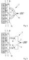
- Fig. 1 an air suction system 3 designed according to the invention is shown, in which charge air is conveyed into a distributor pipe 4 through an air duct 5.
- Gutsaugstrom 3 is designed for an internal combustion engine 1 with two rows of cylinders such that an intake manifold or plenum 6 is provided for each row of cylinders. The air supply takes place in the middle of the manifold 4.
- a throttle body not shown flanged.
- There are provided at each plenum 6 three intake manifolds 7 per row of cylinders, via which the charge air can be supplied to the inlet channel, not shown in the cylinder head and then the combustion chamber. Both plenums 6 are connected to a central distribution pipe 4.
- the respective plenum 6 is integrally formed with the suction tubes 7.
- a distributor tube 4 is arranged between the two plenums 6, which in the present embodiment is formed from a distributor module 4a and from two tube sections 4b, which are formed integrally with the respective plenum.
- the connection can be made by means of band clamps or with a bayonet-like closure.
- a distributor tube length L V is dimensioned as a function of an equivalent distributor tube diameter D V in such a way that a reduction of the charge pressure of the combustion air within the air suction system 3 takes place through a targeted expansion, the expansion taking place partly in the plenum and / or inside the distributor tube.
- the expansion takes place in a region between an entry of the combustion air into the distributor pipe 4, for example from the distributor module 4a, and an exit from the suction pipe 7.
- oscillation occurs within the air suction system, wherein the expansion of the charge air relative to the respective combustion chamber can be achieved continuously within the air suction system, but not necessarily uniformly. This allows the charge air temperature when entering the combustion chamber and thus the fuel / air mixture temperature in the combustion chamber be lowered, so that the engine power can be increased while lowering the specific fuel consumption.
- the oscillating air in the air intake system 3 is sucked during the cooler expansion phase for the mixture preparation, whereby the temperature of the fuel / air mixture is reduced in the combustion chamber.
- the present invention is characterized in that the expansion suction system 3 described here is well suited for internal combustion engines 1 with six or four cylinders.
- the manifold tube length Lv shall be determined by the following formula: 200 - 4 / 3 * L S + 1.7 * n N - 2.22 * D V - 30 ⁇ L v ⁇ 7.2 * 10 6 / n N - 1.5 * L S
- the range for the manifold tube length Lv in which the expansion aspirator can achieve beneficial results is determined by the formula: 34 * D V - 650 - 4 / 3 * L S ⁇ L V
- Ls corresponds to a suction pipe length between the plenum 6 and the cylinder head, not shown.
- the value L V stands for the manifold tube length, which is to be determined differently depending on the embodiment.
- L V is the tube length of the connecting tube between the first and second plenums 6.
- n N corresponds to a rated engine speed at which maximum power is achieved.
- V V ⁇ A V x dx .
- a M V V / L V
- the distribution pipe length L V must be set equal to the distance between the two plenums 6.
- the distributor tube length L V is composed of the lengths of the two sections L V1 and L V2 , wherein in the third embodiment according to Fig. 4 the distributor tube length corresponds to the arc length of the distributor tube 4.
- the distributor tube length L V is composed of the two section lengths L V1 and L V2 .
- the fifth embodiment is according to Fig. 6 to set the manifold tube length L v equal to the distance between the two Plenen 6, wherein in the sixth embodiment according to Fig. 7 the distributor tube length corresponds to the arc length of the distributor tube 4.
- the suction tubes 7 have a length L S , which is below 200 or 150 mm, preferably between 110 and 140 mm.
- the design of the distributor tube length L V as a function of the equivalent distributor tube diameter D V is to be selected such that a ratio of equivalent distributor tube diameter D V to distributor tube length L V is in a range of 0.05 to 0.14, in particular in a range of 0 , 06 to 0.13.
- the internal combustion engine 1 described here operates on the four-stroke principle, wherein the present invention is also suitable for two-stroke internal combustion engines.
- the longitudinal movement of the piston extends between a top dead center OT and a bottom dead center UT.
- combustion air is supplied to the combustion chamber through an inlet channel or a suction pipe 7, wherein the piston moves in a downward movement from a charge exchange dead center LW-TDC to a lower charge exchange dead center UT.
- the piston moves in an upward movement up to an upper ignition dead center ZOT, around which the ignition is made.
- the piston expands in a downward movement to a bottom dead center, wherein in a last cycle of the piston in an upward movement up to an upper charge exchange dead center LW-OT expels the gases from the combustion chamber.
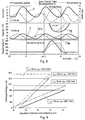
- the dimensions of the opposed Lucassauganlagen according Fig. 8 were chosen to better illustrate the characteristic features so that the typical differences stand out particularly clearly.
- the selected diameter of the resonance tube of the used for comparison resonance suction is 120 mm, the tube length was tuned for 6000 1 / min.
- the suction tank or Plenen 6 correspond to those of a sports car with six cylinders.
- the suction tubes were assumed to be the same and extremely short with 50 mm length in all three examples.
- Fig. 8 In the upper diagram in Fig. 8 are the pressure gradients in plenum 6 after Fig. 13 to 16 shown.
- the constant pressure in the tank marks the boost pressure.
- the charge pressure P that is to say the time-averaged value, is lower by approximately 0.25 bar, because the resonance charge is added for charging by the compressor.
- the boost pressure P is about 0.25 bar above that of the calming tank system and 0.5 bar above that of the resonance system.
- the pressure amplitudes are significantly higher than known from naturally aspirated engines, since due to the higher density of the charge air correspondingly more mass oscillates between the plumes 6.
- Fig. 8 The phase angles of the pressure oscillation differ by approx. 70 ° crank angle. Nevertheless, up to 90 ° phase difference is possible due to other geometries. Due to the phase position of the pressure P, different mass flow characteristics are established at the inlet. For example, if you compare that Mass flow curve with the temperature profile in plenary 6 of the cylinder bank row 1-2-3 according to Fig. 8 respectively. Fig. 13 to 16 , it can be seen that in the Expansionssaugstrom during 120 degrees crank angle of 90 degrees after the upper charge cycle dead center LW-TDC to 20 degrees after the lower charge exchange dead center UT, the temperature in plenum 6 below its average T medium decreases.
- a maximum valve lift at the inlet in a second half of the intake stroke is set, ie, between the upper charge cycle dead center LW-OT and the bottom dead center UT.
- the present invention is characterized in that the air suction system 3 according to the invention is designed such that at the time of combustion air intake within the air suction system 3, in particular in plenum 6 and in the suction pipes 2, a gas-dynamic expansion prevails. As a result, the combustion air substantially at a low temperature T min when the combustion air flows into the combustion chamber.
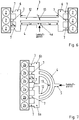
- a second embodiment is shown, in which in the middle of the manifold 4 instead of the distributor module 4a, a container 4c is provided.
- the manifold tube length L V is set from the distances together, which lie between the respective plenum 6 and the container 4c.
- the internal combustion engine 1 according to the invention also has six cylinders, which are arranged in series.
- the air suction system 3 is designed such that the combustion air is split such that a first plenum 6a is provided for the three front cylinders 2a, wherein a second plenum 6b is provided for the remaining three cylinders 2b.
- the manifold 4 is arcuate, wherein the manifold tube length LV corresponds to the arc length.
- the manifold 4 may be formed in any conceivable shape, for example, arcuate, straight or square or as a combination of different shapes, depending on the cylinder arrangement and motor construction within the scope of the invention.
- FIG Fig. 5 A modified form of the third embodiment is shown in FIG Fig. 5 according to a fourth embodiment, in which case the distributor tube 4 is divided into two sections, wherein a container 11 is positioned between the air guide channel 5 and the respective distributor tube sections 10.
- the manifold pipe length L V is composed of the two manifold pipe section lengths L V1 and L V2 .
- a fifth embodiment of the invention according to Fig. 6 is an additional manifold 12 is disposed between the plenums 6, which can be switched by a switching element, designed here as a flap 13, depending on the engine parameters.
- a switching element designed here as a flap 13
- the size of the equivalent distributor diameter D V is adjustable. Thereby, the achievable expansion of the charge air as a function of the speed of the internal combustion engine 1 can be adjusted.
- the arrangement of an additional manifold 12 with a switching flap 13 is also conceivable in all previously described embodiments.
- one or two additional distributor tubes 12 are to be positioned at the corresponding points for setting the size of the equivalent distributor diameter D V.
- Illustrated sixth embodiment illustrates a modified form of the fifth embodiment Fig. 4 represents.
- Fig. 12 are exemplary curves of the charge temperature T B in the combustion chamber after the end of the inflow of the expanded charge air is shown in the combustion chamber.
- Fig. 12 are different temperature values as a function of the speed of the internal combustion engine 1 shown.
- a certain equivalent distributor diameter D V can be set by the additional switchable distributor tube 12 and thus a coordinated expansion of the charge air can be achieved. Accordingly, the setting of a lowest temperature of the charge air at the time of entry into the combustion chamber in dependence on the operating parameters is made possible, so that an optimal efficiency at the respective operating point of the internal combustion engine 1 is present.
- the geometric design of the air intake system 3 leads to such a charge-air expansion that the expansion phase of the charge-air oscillation in the second half of the second intake according to Fig. 8 , upper diagram, lies.
- the second half of the intake come according to Fig. 8
- the lowest temperature values of the charge air are achieved.
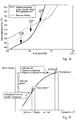
- Due to the relatively cold aspirated air masses then results according to the invention a combustion chamber cylinder filling with a relatively lower temperature. This effect causes a shift of the knock limit toward early according to Fig. 11 so that a previous ignition is possible.
- the engine output can be increased by setting the ignition timing of the engine 1 earlier than in warmer cylinder charge. This leads to a significant performance gain. It is conceivable by the lower knock tendency achieved an increase in the compression ratio of the internal combustion engine.
- the compressor 8 sets an adjusted charge pressure which is higher than in the case of conventional supercharged internal combustion engines.
- By such a boost pressure increase results in a charge air temperature increase by about 10 degrees before the charge air cooler 9, wherein after the charge air cooler 9, a charge air temperature increase of about 2 to 3 degrees is measured.
- the set expansion causes a further reduction of the charge air temperature, so that at the inlet of the combustion chamber while maintaining the desired boost pressure level, a low charge air temperature than the usual temperatures Fig. 8 and 10 is present. Therefore, the higher air flow rate is maintained in the combustion chamber and at the same time an increase in performance by the displacement of the knock limit of the internal combustion engine 1 according to 10 and 11 achieved.
- the present invention will be explained in detail with reference to the air intake system 3 for a six-cylinder engine with two cylinder banks.
- the manifold 4 of the air suction system 3 is longer and smaller in diameter, the individual suction tubes 7 are formed shorter.
- the air intake system of the invention reverses the resonance charging effect at higher engine speeds, so that expansion is utilized instead of compression.
- expansion is utilized instead of compression.
- the air is expanded.
- the air is cooled, so that a lower temperature of the fuel-air mixture in the combustion chamber is achieved. This makes it possible to ignite the cooler fuel-air mixture optimized performance.
- the charge pressure ie the value determined over time
- the boost pressure is approximately 0.25 bar above that of the contact container system and 0.5 bar above that of the resonance system.
- the pressure amplitudes are significantly higher than those of the naturally aspirated engines, since the higher density of the charge air causes correspondingly more mass to oscillate between the plenums 6.
- the phase angles of the pressure oscillations differ by approx. 70 ° crank angle. Due to the phase position of the pressure, different mass flow curves at the inlet in accordance with the lower diagram in Fig. 8 on.
- Fig. 13 to 16 is the spatial waveform, as occurs in the air intake system 3 according to the invention, shown.
- the mass flow in the manifold and in the respective intake manifolds of a cylinder bank is shown.
- the air mass within the air intake system 3 oscillates around the manifold center due to the staggered opening and closing of the intake valves. Accordingly, the air mass oscillates between the two plumes 6 and around the manifold center.
- the different path positions at the right end of the Fig. 13 to 16 arise from the different run lengths through the plenum 6 of the cylinder bank, here the cylinders 1, 2 and 3.
- the cylinder bank 1-2-3 in the Fig. 13 to 16 shown on the right.
- Fig. 13 the charge air flows everywhere in the direction of the cylinder bank 1-2-3, the figure in Fig. 13 represents a momentary recording, which corresponds to a time shortly before the charge cycle dead center LW-OT.
- the representation in Fig. 14 is also a snapshot compared to the Fig. 13 a piston position corresponds to the 60 ° crank angle later than the off Fig. 13 ,
- Fig. 15 also shown an instantaneous view, which corresponds to a time at which the piston is between the charge cycle and the bottom dead center.
- this illustration according to Fig. 15 is the air intake process for the cylinder No. 1 shown, in which case the air intake between the time of maximum piston speed and shortly before reaching a maximum intake valve.
- the charge air oscillates in the intake system in the direction of the opposite cylinder bank to cylinder No. 6.
- the internal combustion engine shown here is a firing order 1, 6, 2, 4, 3 and 5 before. Accordingly, the air is drawn to the right in the suction pipe 7 of the cylinder No. 1, so that the charge air expands in the plenum 6.
- FIG. 4 shows four time recordings within one cycle of the charge air oscillation with a 240 ° crank angle oscillation period. This results from the fact that the present internal combustion engine passes through three cycles per four-stroke cycle within 720 ° crank angle.
- the air intake system 3 according to the invention achieves a significant lowering of the temperature of the charge air below the average value T Mittel .
Landscapes
- Engineering & Computer Science (AREA)
- Chemical & Material Sciences (AREA)
- Combustion & Propulsion (AREA)
- Mechanical Engineering (AREA)
- General Engineering & Computer Science (AREA)
- Characterised By The Charging Evacuation (AREA)
- Supercharger (AREA)
Claims (17)
- Moteur à combustion interne (1) comprenant une pluralité de cylindres (2), un système d'aspiration d'air (3), un compresseur (8) destiné à transporter l'air de combustion et une chambre de combustion disposée dans le cylindre (2) et délimitée entre un piston et une culasse,- le système d'aspiration d'air (3) étant formé d'au moins un tuyau de distribution (4), d'une pluralité de tuyaux d'aspiration (7) et d'au moins un collecteur (6), le collecteur (6) étant positionné entre le tuyau de distribution (4) et les tuyaux d'aspiration {7},- l'air de combustion étant acheminé au système d'aspiration d'air (3) par le biais d'un conduit d'amenée d'air (5) qui débouche dans le tuyau de distribution (4), et- la pression de suralimentation (p) de l'air de combustion étant réduite de la sortie du compresseur (8) jusqu'à l'entrée dans la chambre de combustion du moteur à combustion interne (1),caractérisé en ce que- le système d'aspiration d'air (3) est conçu de telle sorte qu'au moins une partie de la masse d'air entre dans la chambre de combustion du moteur à combustion interne {1} pendant une phase d'expansion de la masse d'air dans le système d'aspiration d'air, une expansion continue, mais pas nécessairement uniforme, entre l'entrée de l'air de combustion dans le tuyau de distribution (4) et l'entrée de l'air de combustion dans la chambre de combustion pouvant être atteinte.
- Moteur à combustion interne (1) selon la. revendication 1, caractérisé en ce qu'une longueur de tuyau de distribution est dimensionnée de telle sorte qu'une réduction de la pression de suralimentation (P) dans le système d'aspiration d'air (3) peut être obtenue au moment de l'aspiration d'air.
- Moteur à combustion interne (1) selon la revendication 1 ou 2, caractérisé en ce que la température de la masse d'air, aspirée par le cylindre respectif, est réduite au moment de l'aspiration d'air entre le collecteur (6), et la chambre de combustion du moteur à combustion interne (1).
- Moteur à combustion interne (1) selon la revendication 3, caractérisé en ce que la réduction de la température de la masse d'air au-dessous de la valeur de température moyenne (Tmoyenne) est effectuée dans la plage angulaire de vilebrequin comprise entre 50° après le point mort haut de cycle de charge (LW-OT) et 40° après le point mort bas de cycle de charge (UT), en particulier entre 90° après le point mort haut d'échange de charge (LW-OT) et 20° après le point mort bas d'échange de charge (UT).
- Moteur à combustion interne (1) selon l'une des revendications 1 à 4, caractérisé en ce que le système d'aspiration d'air (3) est conçu de telle sorte qu'une longueur de tuyau de distribution (Lv) est dimensionnée en fonction d'un diamètre de tuyau de distribution équivalent (Dv).
- Moteur à combustion interne (1) selon la revendication 5, caractérisé en ce que le choix de la longueur de tuyau de distribution (Lv) est effectué en fonction d' un diamètre de tuyau de distribution équivalent (Dv) de telle sorte que le rapport du diamètre de tuyau de distribution équivalent (Dv) à la longueur de tuyau de distribution (Lv) est de 0,05 à 0,14, ou de 0,06 à 0,13.
- Moteur à combustion interne (1) selon l'une des revendications 1 à 6, caractérisé en ce que le système d'aspiration d'air (3) est conçu de telle sorte que la longueur de tuyau d'aspiration (Ls) soit inférieure à 200 mm ou à 150 mm.
- Moteur à combustion interne (1) selon l'une des revendications 1 à 7, caractérisé en ce que le système d'aspiration d'air (3) comporte deux collecteurs (6), le tuyau de distribution (4) étant formé d'un module de distribution (4a) et de deux parties de tuyau de distribution (4b), chaque partie de tuyau de distribution (4b) étant positionnée entre le module de distribution (4a) et l'un des collecteurs (6).
- Moteur à combustion interne (1) selon l'une des revendications 1 à 8, caractérisé en ce que le moteur à combustion interne (1) est conçu comme un moteur à combustion interne à allumage par étincelle, en particulier du type à cylindres opposés, le nombre de cylindres (2) étant de quatre, six ou huit.
- Moteur à combustion interne (1) selon l'une des revendications 1 à 9, caractérisé en ce que la longueur de tuyau de distribution (Lv) est supérieure à une longueur L1 qui est déterminée par une première formule ;

- Moteur à combustion interne (1) selon l'une des revendications 1 à 9, caractérisé en ce que la longueur de tuyau de distribution (Lv) est inférieure à une longueur (L2) qui est déterminée par une deuxième formule :

- Moteur à combustion interne (1) selon l'une des revendications 1 à 9, caractérisé en ce que la longueur de tuyau de distribution (Lv) est supérieure à une longueur (L3) qui est déterminée par une troisième formule :

- Moteur à combustion interne (1) selon l'une des revendications 1 à 12, caractérisé en ce qu'il est prévu un deuxième tube de distribution commutable (12).
- Moteur à combustion interne (1) selon l'une des revendications 1 à 13, caractérisé en ce qu'un volet de commutation (13), permettant de régler la dimension du diamètre de tuyau de distribution équivalent (Dv), est prévu dans le deuxième tuyau de distribution (4).
- Moteur à combustion interne (1) selon l'une des revendications 1 à 14, caractérisé en ce que le moteur à combustion interne (1) comporte un turbocompresseur à gaz d'échappement à géométrie de turbine réglable.
- Moteur à combustion interne (1) selon l'une des revendications 1 à 15, caractérisé en ce qu'une augmentation supplémentaire de la pression de suralimentation à travers le compresseur (8) est réglable, les valeurs de pression de suralimentation réglées étant supérieures de 5 % à 15 % à une valeur comprise entre 0,9 bar et 1,5 bar.
- Moteur à combustion interne (1) selon l'une des revendications 1 à 16, caractérisé en ce que l'expansion pouvant être atteinte dans le système d'aspiration d'air (3) peut être réglée en fonction de paramètres de fonctionnement, en particulier de la vitesse de rotation (nN) du moteur à combustion interne (1).
Applications Claiming Priority (2)
| Application Number | Priority Date | Filing Date | Title |
|---|---|---|---|
| DE102007033324A DE102007033324A1 (de) | 2007-07-16 | 2007-07-16 | Brennkraftmaschine |
| DE102007052310A DE102007052310A1 (de) | 2007-10-31 | 2007-10-31 | Brennkraftmaschine |
Publications (3)
| Publication Number | Publication Date |
|---|---|
| EP2017447A2 EP2017447A2 (fr) | 2009-01-21 |
| EP2017447A3 EP2017447A3 (fr) | 2014-01-22 |
| EP2017447B1 true EP2017447B1 (fr) | 2019-12-04 |
Family
ID=39720635
Family Applications (1)
| Application Number | Title | Priority Date | Filing Date |
|---|---|---|---|
| EP08010669.3A Active EP2017447B1 (fr) | 2007-07-16 | 2008-06-12 | Moteur à combustion interne |
Country Status (3)
| Country | Link |
|---|---|
| US (1) | US8281761B2 (fr) |
| EP (1) | EP2017447B1 (fr) |
| JP (1) | JP2009019633A (fr) |
Families Citing this family (8)
| Publication number | Priority date | Publication date | Assignee | Title |
|---|---|---|---|---|
| DE102007033324A1 (de) * | 2007-07-16 | 2009-01-22 | Dr. Ing. H.C. F. Porsche Aktiengesellschaft | Brennkraftmaschine |
| DE102008041037A1 (de) * | 2008-08-06 | 2010-02-11 | Robert Bosch Gmbh | Verfahren und Vorrichtung einer Steuerung für einen Start-Stopp-Betrieb einer Brennkraftmaschine |
| FR2979950A1 (fr) * | 2011-09-13 | 2013-03-15 | Peugeot Citroen Automobiles Sa | Moteur a combustion interne equipe d'un turbocompresseur |
| JP5904108B2 (ja) * | 2011-12-19 | 2016-04-13 | 株式会社デンソー | 排気熱交換装置 |
| GB201305616D0 (en) * | 2013-03-27 | 2013-05-15 | Cummins Inc | Intake manifold overpressure compensation for internal combustion engines |
| JP6418782B2 (ja) * | 2014-05-16 | 2018-11-07 | キヤノン株式会社 | ロボットシステムの制御方法、プログラム、記録媒体、ロボットシステム、及び診断装置 |
| DE102017221747B3 (de) * | 2017-12-04 | 2019-02-28 | Bayerische Motoren Werke Aktiengesellschaft | Verbrennungsmotor, Kraftfahrzeug mit einem solchen sowie Verfahren zum Betreiben eines Verbrennungsmotors |
| FR3087225B1 (fr) * | 2018-10-16 | 2021-01-22 | Renault Sas | Systeme d'admission d'air equipe d'un moyen de limitation du debit d'air |
Family Cites Families (24)
| Publication number | Priority date | Publication date | Assignee | Title |
|---|---|---|---|---|
| DE1526312A1 (de) * | 1963-07-23 | 1969-02-13 | Maschf Augsburg Nuernberg Ag | Mehrzylindrige,luftverdichtende Hubkolbenmaschine,insbesondere Viertakt-Brennkraftmaschine |
| AT330506B (de) * | 1971-09-28 | 1976-07-12 | Autoipari Kutato Intezet | Kolbenbrennkraftmaschine mit abgasturboaufladung |
| HU173034B (hu) | 1975-05-13 | 1979-02-28 | Autoipari Kutato Intezet | Sistema truboprovodov dlja podvoda svezhego gaza k shesticilindrovomu dvigatelju s turbonasosom |
| HU175877B (en) | 1978-07-07 | 1980-11-28 | Autoipari Kutato Intezet | Fresh gas duct system of resanator for internal combustion piston engines |
| HU188702B (en) | 1981-10-20 | 1986-05-28 | Autipari Kutato Intezet,Hu | Internal combustion piston engine with resonance fresh-gas system improving the fresh-gas supply |
| DE3344950A1 (de) | 1983-12-13 | 1985-06-20 | M.A.N. Maschinenfabrik Augsburg-Nürnberg AG, 8500 Nürnberg | Kompaktes frischgas-eintrittssystem fuer motoren mit kombinierter aufladung |
| DE3627312A1 (de) | 1985-08-22 | 1987-02-26 | Volkswagen Ag | Brennkraftmaschine mit einem ladeluftverdichter und einem ladeluftkuehler |
| JP2863927B2 (ja) * | 1988-03-15 | 1999-03-03 | マツダ株式会社 | エンジンの吸気装置 |
| JPH0533660A (ja) * | 1991-07-30 | 1993-02-09 | Hino Motors Ltd | 排気ターボ過給式エンジンの給気冷却装置 |
| AU6674596A (en) | 1995-06-23 | 1997-01-22 | Martin C. Fields | Process and apparatus for sequential breathing |
| DE29600060U1 (de) | 1996-01-03 | 1996-03-07 | Schmitt, Peter, 44369 Dortmund | Ansaugrohr für aufgeladene und selbstsaugende Verbrennungsmotoren |
| JP3261964B2 (ja) * | 1996-02-16 | 2002-03-04 | トヨタ自動車株式会社 | 内燃機関の可変吸気装置 |
| DE19814970B4 (de) * | 1998-04-03 | 2006-03-02 | Dr.Ing.H.C. F. Porsche Ag | Sauganlage |
| DE19842724A1 (de) * | 1998-09-18 | 2000-03-23 | Porsche Ag | Sauganlage |
| DE10002482A1 (de) | 2000-01-21 | 2001-07-26 | Audi Ag | Vorrichtung zur Ladeluftkühlung einer aufgeladenen Brennkraftmaschine |
| NO310842B1 (no) | 2000-01-24 | 2001-09-03 | Ulstein Bergen As | Fremgangsmåte og anordning ved drift av en forbrenningsmotor |
| DE10043532B4 (de) * | 2000-09-05 | 2010-11-04 | Dr. Ing. H.C. F. Porsche Aktiengesellschaft | Luftfiltereinrichtung für eine mehrzylindrige Brennkraftmaschine |
| FR2818319B1 (fr) * | 2000-12-19 | 2003-06-27 | Renault | Circuit d'admission d'air d'un moteur suralimente |
| JP2002188536A (ja) * | 2000-12-22 | 2002-07-05 | Mitsubishi Motors Corp | 過給機付き内燃機関 |
| DE10202322A1 (de) * | 2002-01-23 | 2003-07-31 | Daimler Chrysler Ag | Brennkraftmaschine mit einem Abgasturbolader und Verfahren zum Betrieb einer solchen Brennkraftmaschine |
| DE10239110B4 (de) * | 2002-08-27 | 2004-08-19 | Caterpillar Motoren Gmbh & Co. Kg | Aufladesystem für eine Brennkraftmaschine |
| DE102004029746B4 (de) * | 2004-06-19 | 2014-06-12 | Dr. Ing. H.C. F. Porsche Aktiengesellschaft | Sauganlage für eine Brennkraftmaschine mit mindestens zwei Zylinderbankreihen |
| JP2006125223A (ja) * | 2004-10-26 | 2006-05-18 | Toyota Motor Corp | 内燃機関 |
| DE102007033324A1 (de) * | 2007-07-16 | 2009-01-22 | Dr. Ing. H.C. F. Porsche Aktiengesellschaft | Brennkraftmaschine |
-
2008
- 2008-06-12 EP EP08010669.3A patent/EP2017447B1/fr active Active
- 2008-07-15 JP JP2008183396A patent/JP2009019633A/ja active Pending
- 2008-07-16 US US12/174,309 patent/US8281761B2/en active Active
Non-Patent Citations (1)
| Title |
|---|
| None * |
Also Published As
| Publication number | Publication date |
|---|---|
| JP2009019633A (ja) | 2009-01-29 |
| EP2017447A2 (fr) | 2009-01-21 |
| US8281761B2 (en) | 2012-10-09 |
| US20090020097A1 (en) | 2009-01-22 |
| EP2017447A3 (fr) | 2014-01-22 |
Similar Documents
| Publication | Publication Date | Title |
|---|---|---|
| EP2017447B1 (fr) | Moteur à combustion interne | |
| EP2179153B1 (fr) | Moteur à combustion interne | |
| DE69206718T3 (de) | Brennkraftmaschine mit Funkenentzündung | |
| DE69133098T2 (de) | Abgasrückführungssystem für eine Brennkraftmaschine | |
| DE69214234T2 (de) | Brennkraftmaschine mit Kompressor | |
| DE102008044244A1 (de) | Brennkraftmaschine | |
| DE102012213936B4 (de) | Aufgeladener Vier-Zylinder-Reihenmotor mit parallel angeordneten Turbinen und Verfahren zum Betreiben eines derartigen Vier-Zylinder-Reihenmotors | |
| DE102011084834A1 (de) | Brennkraftmaschine mit mehreren Auslaßöffnungen je Zylinder und Ladungswechselverfahren für eine derartige Brennkraftmaschine | |
| DE102013210597A1 (de) | Brennkraftmaschine mit Teilabschaltungund Verfahren zum Betreiben einer derartigen Brennkraftmaschine | |
| EP2923073B1 (fr) | Procédé de control d'un moteur à combustion à allumage commandé ayant un turbocompresseur | |
| DD279923A5 (de) | Kolbenbrennkraftmaschine mit frischgasresonanzaufladung | |
| DE102007014447A1 (de) | Aufgeladener Ottomotor mit variabler Sauganlage | |
| DE112015004484B4 (de) | Dieselmotor | |
| EP2103790B1 (fr) | Méthode d'utilisation d'un moteur à combustion avec auto-allumage et injecteur optimisé | |
| DE102018203291B4 (de) | Brennkraftmaschine mit Zylinderkopf und Verfahren zur Herstellung eines Zylinderkopfes einer derartigen Brennkraftmaschine | |
| DE102007052310A1 (de) | Brennkraftmaschine | |
| WO2007056784A2 (fr) | Moteur a combustion interne | |
| DE102015200047B4 (de) | Verfahren zum Betreiben einer Brennkraftmaschine mit Teilabschaltung | |
| WO2014095234A1 (fr) | Procédé pour faire fonctionner un moteur à combustion interne à commande de soupapes variable et recirculation des gaz d'échappement | |
| DE102013221109B4 (de) | Aufgeladene fremdgezündete Brennkraftmaschine mit Direkteinspritzung und Verfahren zum Betreiben einer derartigen Brennkraftmaschine | |
| EP1612389B1 (fr) | Moteur à combustion interne comprenant au moins quatre cylindres et procédé d'optimisation des échanges gaseux dans un tel moteur | |
| DE102013206158A1 (de) | Brennkraftmaschine mit abschaltbarem Zylinderund Verfahren zum Betreiben einer derartigen Brennkraftmaschine | |
| DE102004027474B4 (de) | Viertakt-Verbrennungsmotor mit Abgasturbolader und Verfahren zur Optimierung seines Betriebs | |
| DE2449370C3 (de) | Freisaugende, luftverdichtende Achtzylinder-Brennkraftmaschine | |
| DE102014208726B4 (de) | Selbstzündende Brennkraftmaschine mit Ansaugsystem umfassend eine Gesamtansaugleitung |
Legal Events
| Date | Code | Title | Description |
|---|---|---|---|
| PUAI | Public reference made under article 153(3) epc to a published international application that has entered the european phase |
Free format text: ORIGINAL CODE: 0009012 |
|
| AK | Designated contracting states |
Kind code of ref document: A2 Designated state(s): AT BE BG CH CY CZ DE DK EE ES FI FR GB GR HR HU IE IS IT LI LT LU LV MC MT NL NO PL PT RO SE SI SK TR |
|
| AX | Request for extension of the european patent |
Extension state: AL BA MK RS |
|
| RAP1 | Party data changed (applicant data changed or rights of an application transferred) |
Owner name: DR. ING. H.C. F. PORSCHE AG |
|
| PUAL | Search report despatched |
Free format text: ORIGINAL CODE: 0009013 |
|
| AK | Designated contracting states |
Kind code of ref document: A3 Designated state(s): AT BE BG CH CY CZ DE DK EE ES FI FR GB GR HR HU IE IS IT LI LT LU LV MC MT NL NO PL PT RO SE SI SK TR |
|
| AX | Request for extension of the european patent |
Extension state: AL BA MK RS |
|
| RIC1 | Information provided on ipc code assigned before grant |
Ipc: F02B 27/02 20060101AFI20131219BHEP |
|
| 17P | Request for examination filed |
Effective date: 20140722 |
|
| RBV | Designated contracting states (corrected) |
Designated state(s): AT BE BG CH CY CZ DE DK EE ES FI FR GB GR HR HU IE IS IT LI LT LU LV MC MT NL NO PL PT RO SE SI SK TR |
|
| AKX | Designation fees paid |
Designated state(s): DE FR GB IT |
|
| 17Q | First examination report despatched |
Effective date: 20171128 |
|
| GRAP | Despatch of communication of intention to grant a patent |
Free format text: ORIGINAL CODE: EPIDOSNIGR1 |
|
| INTG | Intention to grant announced |
Effective date: 20190305 |
|
| GRAS | Grant fee paid |
Free format text: ORIGINAL CODE: EPIDOSNIGR3 |
|
| GRAA | (expected) grant |
Free format text: ORIGINAL CODE: 0009210 |
|
| AK | Designated contracting states |
Kind code of ref document: B1 Designated state(s): DE FR GB IT |
|
| REG | Reference to a national code |
Ref country code: GB Ref legal event code: FG4D Free format text: NOT ENGLISH |
|
| REG | Reference to a national code |
Ref country code: DE Ref legal event code: R096 Ref document number: 502008016963 Country of ref document: DE |
|
| REG | Reference to a national code |
Ref country code: DE Ref legal event code: R097 Ref document number: 502008016963 Country of ref document: DE |
|
| PLBE | No opposition filed within time limit |
Free format text: ORIGINAL CODE: 0009261 |
|
| STAA | Information on the status of an ep patent application or granted ep patent |
Free format text: STATUS: NO OPPOSITION FILED WITHIN TIME LIMIT |
|
| 26N | No opposition filed |
Effective date: 20200907 |
|
| P01 | Opt-out of the competence of the unified patent court (upc) registered |
Effective date: 20230526 |
|
| PGFP | Annual fee paid to national office [announced via postgrant information from national office to epo] |
Ref country code: FR Payment date: 20230627 Year of fee payment: 16 |
|
| PGFP | Annual fee paid to national office [announced via postgrant information from national office to epo] |
Ref country code: IT Payment date: 20230623 Year of fee payment: 16 Ref country code: GB Payment date: 20230620 Year of fee payment: 16 |
|
| GBPC | Gb: european patent ceased through non-payment of renewal fee |
Effective date: 20240612 |
|
| PG25 | Lapsed in a contracting state [announced via postgrant information from national office to epo] |
Ref country code: FR Free format text: LAPSE BECAUSE OF NON-PAYMENT OF DUE FEES Effective date: 20240630 |
|
| PG25 | Lapsed in a contracting state [announced via postgrant information from national office to epo] |
Ref country code: IT Free format text: LAPSE BECAUSE OF NON-PAYMENT OF DUE FEES Effective date: 20240612 Ref country code: GB Free format text: LAPSE BECAUSE OF NON-PAYMENT OF DUE FEES Effective date: 20240612 |
|
| PGFP | Annual fee paid to national office [announced via postgrant information from national office to epo] |
Ref country code: DE Payment date: 20250414 Year of fee payment: 18 |