EP2017464A1 - Kraftstoffzufuhrpumpe - Google Patents
Kraftstoffzufuhrpumpe Download PDFInfo
- Publication number
- EP2017464A1 EP2017464A1 EP07742132A EP07742132A EP2017464A1 EP 2017464 A1 EP2017464 A1 EP 2017464A1 EP 07742132 A EP07742132 A EP 07742132A EP 07742132 A EP07742132 A EP 07742132A EP 2017464 A1 EP2017464 A1 EP 2017464A1
- Authority
- EP
- European Patent Office
- Prior art keywords
- fuel
- valve piston
- fastener
- valve
- spring seat
- Prior art date
- Legal status (The legal status is an assumption and is not a legal conclusion. Google has not performed a legal analysis and makes no representation as to the accuracy of the status listed.)
- Withdrawn
Links
- 239000000446 fuel Substances 0.000 title claims abstract description 271
- 229910000831 Steel Inorganic materials 0.000 claims description 11
- 239000010959 steel Substances 0.000 claims description 11
- 229910045601 alloy Inorganic materials 0.000 claims description 6
- 239000000956 alloy Substances 0.000 claims description 6
- 238000010586 diagram Methods 0.000 description 17
- 238000002347 injection Methods 0.000 description 13
- 239000007924 injection Substances 0.000 description 13
- 239000002828 fuel tank Substances 0.000 description 11
- 238000000034 method Methods 0.000 description 11
- 239000000463 material Substances 0.000 description 9
- 238000003466 welding Methods 0.000 description 6
- 230000002093 peripheral effect Effects 0.000 description 4
- 239000000314 lubricant Substances 0.000 description 3
- 230000000630 rising effect Effects 0.000 description 3
- 238000010008 shearing Methods 0.000 description 3
- 238000002485 combustion reaction Methods 0.000 description 2
- 238000001514 detection method Methods 0.000 description 2
- 239000002245 particle Substances 0.000 description 2
- 230000001105 regulatory effect Effects 0.000 description 2
- 229910000599 Cr alloy Inorganic materials 0.000 description 1
- 229910000677 High-carbon steel Inorganic materials 0.000 description 1
- 230000003321 amplification Effects 0.000 description 1
- 230000001276 controlling effect Effects 0.000 description 1
- 230000000694 effects Effects 0.000 description 1
- KHYBPSFKEHXSLX-UHFFFAOYSA-N iminotitanium Chemical compound [Ti]=N KHYBPSFKEHXSLX-UHFFFAOYSA-N 0.000 description 1
- 238000011835 investigation Methods 0.000 description 1
- 230000007774 longterm Effects 0.000 description 1
- 230000001050 lubricating effect Effects 0.000 description 1
- 239000010687 lubricating oil Substances 0.000 description 1
- 229910001000 nickel titanium Inorganic materials 0.000 description 1
- 238000003199 nucleic acid amplification method Methods 0.000 description 1
- 238000011045 prefiltration Methods 0.000 description 1
- 238000007789 sealing Methods 0.000 description 1
- 238000011144 upstream manufacturing Methods 0.000 description 1
Images


Classifications
-
- F—MECHANICAL ENGINEERING; LIGHTING; HEATING; WEAPONS; BLASTING
- F04—POSITIVE - DISPLACEMENT MACHINES FOR LIQUIDS; PUMPS FOR LIQUIDS OR ELASTIC FLUIDS
- F04B—POSITIVE-DISPLACEMENT MACHINES FOR LIQUIDS; PUMPS
- F04B1/00—Multi-cylinder machines or pumps characterised by number or arrangement of cylinders
- F04B1/04—Multi-cylinder machines or pumps characterised by number or arrangement of cylinders having cylinders in star- or fan-arrangement
- F04B1/0404—Details or component parts
- F04B1/0452—Distribution members, e.g. valves
-
- F—MECHANICAL ENGINEERING; LIGHTING; HEATING; WEAPONS; BLASTING
- F02—COMBUSTION ENGINES; HOT-GAS OR COMBUSTION-PRODUCT ENGINE PLANTS
- F02M—SUPPLYING COMBUSTION ENGINES IN GENERAL WITH COMBUSTIBLE MIXTURES OR CONSTITUENTS THEREOF
- F02M59/00—Pumps specially adapted for fuel-injection and not provided for in groups F02M39/00 -F02M57/00, e.g. rotary cylinder-block type of pumps
- F02M59/44—Details, components parts, or accessories not provided for in, or of interest apart from, the apparatus of groups F02M59/02 - F02M59/42; Pumps having transducers, e.g. to measure displacement of pump rack or piston
- F02M59/46—Valves
- F02M59/464—Inlet valves of the check valve type
-
- F—MECHANICAL ENGINEERING; LIGHTING; HEATING; WEAPONS; BLASTING
- F04—POSITIVE - DISPLACEMENT MACHINES FOR LIQUIDS; PUMPS FOR LIQUIDS OR ELASTIC FLUIDS
- F04B—POSITIVE-DISPLACEMENT MACHINES FOR LIQUIDS; PUMPS
- F04B53/00—Component parts, details or accessories not provided for in, or of interest apart from, groups F04B1/00 - F04B23/00 or F04B39/00 - F04B47/00
- F04B53/10—Valves; Arrangement of valves
- F04B53/102—Disc valves
- F04B53/1032—Spring-actuated disc valves
-
- F—MECHANICAL ENGINEERING; LIGHTING; HEATING; WEAPONS; BLASTING
- F01—MACHINES OR ENGINES IN GENERAL; ENGINE PLANTS IN GENERAL; STEAM ENGINES
- F01L—CYCLICALLY OPERATING VALVES FOR MACHINES OR ENGINES
- F01L3/00—Lift-valve, i.e. cut-off apparatus with closure members having at least a component of their opening and closing motion perpendicular to the closing faces; Parts or accessories thereof
- F01L3/10—Connecting springs to valve members
-
- F—MECHANICAL ENGINEERING; LIGHTING; HEATING; WEAPONS; BLASTING
- F02—COMBUSTION ENGINES; HOT-GAS OR COMBUSTION-PRODUCT ENGINE PLANTS
- F02M—SUPPLYING COMBUSTION ENGINES IN GENERAL WITH COMBUSTIBLE MIXTURES OR CONSTITUENTS THEREOF
- F02M59/00—Pumps specially adapted for fuel-injection and not provided for in groups F02M39/00 -F02M57/00, e.g. rotary cylinder-block type of pumps
- F02M59/02—Pumps specially adapted for fuel-injection and not provided for in groups F02M39/00 -F02M57/00, e.g. rotary cylinder-block type of pumps of reciprocating-piston or reciprocating-cylinder type
- F02M59/10—Pumps specially adapted for fuel-injection and not provided for in groups F02M39/00 -F02M57/00, e.g. rotary cylinder-block type of pumps of reciprocating-piston or reciprocating-cylinder type characterised by the piston-drive
- F02M59/102—Mechanical drive, e.g. tappets or cams
Definitions
- the present invention relates to a fuel supply pump that is disposed with a fuel inlet valve and particularly to a fuel supply pump that is suited for pressure-feeding high pressure fuel of a large flow rate.
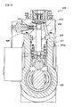
- FIG. 13 shows an example of a fuel supply pump that is used in such accumulator fuel injection system.
- This fuel supply pump 410 is disposed with a cam 429 in a pump housing 421 and includes a cylindrical space 421a in which a plunger barrel 415 is attached above the cam 429, with a fuel inlet valve 422 being attached to an upper open portion of the plunger barrel 415 that is attached in this cylindrical space 421a.
- a fuel pressurization chamber 425 that is closed off by a plunger 423 and the fuel inlet valve 422 is formed, and a fuel passage 431 that is connected to a fuel outlet valve 428 is disposed in the portion that faces the fuel pressurization chamber 425.
- fuel that has been supplied to the fuel pressurization chamber 425 via the fuel inlet valve 422 is pressurized by the plunger 423 that reciprocally moves in accompaniment with the rotation of the cam 429 and is pressure-fed with respect to a common rail via the fuel outlet valve 428.
- the fuel inlet valve 422 that is used in the fuel supply pump is disposed with a valve body 433, a valve piston 435 that includes a collar portion 436 on one end and is slidably held in the valve body 433, a spring 441 that energizes the valve piston 435 in a valve closing direction, and a spring seat 437 that is fixed in the vicinity of an end portion of the valve piston 435 on the opposite side of the end portion where the collar portion 436 is disposed and which receives one end of the spring 441 (see Patent Document 1).
- Fuel is supplied to a fuel reservoir portion 433a via a fuel inlet hole, the fuel inlet valve 422 is opened when the difference between the pressure inside the fuel pressurization chamber 425 and the pressure inside the fuel reservoir portion 433a exceeds a predetermined pressure value, and the fuel is supplied to the inside of the fuel pressurization chamber 425. Meanwhile, the pressure inside the fuel pressurization chamber 425 rises in accompaniment with the rising of the plunger 423 and the pressure inside the fuel reservoir portion 433a drops, whereby the valve piston 435 is seated on a seat portion of the valve body 433 and the fuel inlet valve 422 is closed.
- Patent Document 1 JP-A-2004-211580 ( FIG. 1 , FIG. 13 )
- the valve piston and the spring seat are configured as separate bodies for assembly reasons. Additionally, this fuel inlet valve usually has a size of about 3 to 4 cm, so when the valve piston and the spring seat are to be fixed, laser welding is employed as an easy fixing method. Consequently, it is necessary to select a material that is easy to weld as the material of the valve piston, and it has been difficult to employ a relatively high-strength material such as high-carbon steel. As a result, there has been the potential for the portion of the valve piston that is seated in the valve body to easily wear and for its durability to become poor.
- a fuel supply pump comprising a fuel pressurization chamber for pressurizing fuel to a high pressure and a fuel inlet valve for supplying fuel to the fuel pressurization chamber, wherein the fuel inlet valve is disposed with a valve body, a valve piston that includes a collar portion on one end side and is slidably held in the valve body, a spring that energizes the valve piston in a valve closing direction, and a spring seat that is fixed in the vicinity of an end portion of the valve piston on the opposite side of the one end side and which receives one end of the spring, the valve piston includes, in its outer surface in the vicinity of the end portion on the opposite side, a groove portion to which a fastener for fixing the valve piston and the spring seat locks, the spring seat includes an open portion into which the valve piston is inserted and includes, along an edge of the open portion, a step portion to which the fastener locks, the valve piston is inserted into the open portion of the spring seat, the fastener is thereafter caused to lock to
- the cross-sectional shape of the groove portion or the step portion is a circular arc shape and for the clearance to be disposed by offsetting the center of a circle that draws the circular arc from an outer surface position of the valve piston.
- outer surface position of the valve piston means a surface position on the circumferential direction outer side with respect to the axial line of the valve piston and a surface position that exists when it is assumed that that surface position on the circumferential direction outer side extends.
- a frictional force generating member it is preferable for a frictional force generating member to be intervened between the groove portion or the step portion and the fastener.
- the fastener in configuring the fuel supply pump of the present invention, it is preferable for the fastener to be a C-ring that comprises an alloy that has high elasticity.
- valve piston and the spring seat comprise carburized steel or bearing steel.
- a fuel supply pump comprising a fuel pressurization chamber for pressurizing fuel to a high pressure and a fuel inlet valve for supplying fuel to the fuel pressurization chamber, wherein the fuel inlet valve is disposed with a valve body, a valve piston that includes a collar portion on one end side and is slidably held in the valve body, a spring that energizes the valve piston in a valve closing direction, and a spring seat that is fixed in the vicinity of an end portion of the valve piston on the opposite side of the one end side and which receives one end of the spring, the valve piston includes, in its outer surface in the vicinity of the end portion on the opposite side, a groove portion to which a fastener for fixing the valve piston and the spring seat locks, the spring seat includes an open portion into which the valve piston is inserted and includes, along an edge of the open portion, a step portion to which the fastener locks, the valve piston is inserted into the open portion of the spring seat, the fastener is thereafter caused to lock to
- the valve piston and the spring seat are fixed by a mechanical fixing method that uses a predetermined fastener, so the degree of freedom of selecting the material that configures the valve piston expands, and a high-strength material that is not suited for welding can be selected. Consequently, the strength of the valve piston is raised and wear of the portion that is seated with respect to the valve body can be reduced.
- the fastener and at least one of the groove portion of the valve piston and the step portion of the spring seat to which the fastener locks are placed in a predetermined state of contact, so a situation where shear force acts on the fastener due to the downward pushing force of the valve piston resulting from fuel pressure and the energizing force of the spring can be controlled, and a situation where the fastener sustains damage can be prevented. Consequently, the durability of the fuel inlet valve improves, so even when the pump is caused to rotate at a high speed and is used, the fuel supply pump can stably pressure-feed high pressure fuel of a large flow rate.
- the embodiment of the present invention is a fuel supply pump that comprises a fuel pressurization chamber for pressurizing fuel to a high pressure and a fuel inlet valve for supplying fuel to the fuel pressurization chamber.
- the fuel inlet valve is disposed with a valve body, a valve piston that includes a collar portion on one end side and is slidably held in the valve body, a spring that energizes the valve piston in a valve closing direction, and a spring seat that is fixed in the vicinity of an end portion of the valve piston on the opposite side of the one end side where the collar portion is disposed and which receives one end of the spring
- the valve piston includes, in its outer surface in the vicinity of the end portion on the opposite side, a groove portion to which a fastener for fixing the valve piston and the spring seat locks
- the spring seat includes an open portion into which the valve piston is inserted and includes, along the edge of the open portion, a step portion to which the fastener locks, the valve piston is inserted into the open portion of the
- the overall configuration of the fuel supply pump of the present invention is not particularly limited, and one example thereof is shown in FIG. 1 .
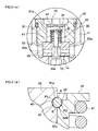
- This fuel supply pump 1 is a so-called line-type pump where cylinders (cylindrical spaces) 11b and 11c in which plungers 13 that pressurize fuel are disposed are disposed in parallel, and the fuel supply pump 1 is disposed with a pump body portion 10 that pressurizes fuel to a high pressure and pressure-feeds the fuel, a feed pump 3 for sucking up fuel from a fuel tank (not shown), and a control valve 5 for regulating the flow rate of the fuel that is to be pressurized.
- this fuel supply pump 1 has a configuration that uses the two plungers 13 to pressurize fuel to a high pressure and pressure-feed the fuel, but the number of the plungers can also be increased to an even greater number in order to pressurize an even larger amount of fuel to a high pressure.
- the feed pump 3 is a part for sucking up the fuel inside the fuel tank and delivering the fuel with respect to the control valve 5.
- This feed pump 3 comprises a gear pump structure that includes a drive gear that is coupled to an end portion of a cam shaft 23 and a passive gear that is coupled to the drive gear, for example, and the feed pump 3 is driven directly or via an appropriate gear ratio with the cam shaft 23.
- This feed pump 3 is driven, whereby the fuel is sucked up from the fuel tank and delivered with respect to the control valve 5 utilizing negative pressure.
- a prefilter (not shown) is intervened between the feed pump 3 and the fuel tank and foreign particles are mixed in with the fuel inside the fuel tank, those foreign particles can be primarily trapped such that they do not flow into the inside of the fuel supply pump 1.
- the control valve 5 is attached to the pump body portion 10 and is a part which, when delivering the fuel that has been delivered from the feed pump 3 to fuel pressurization chambers 14 of the pump body portion 10, regulates the amount of that fuel.
- This control valve 5 can be given a configuration that uses a proportional control valve, for example. Because of this control valve 5, the amount of fuel can be regulated in correspondence to the fuel pressure that internal combustion requires, and the fuel can be sent to the fuel pressurization chambers 14 of the pump body portion 10.
- the fuel supply pump is disposed with an overflow valve that branches from the middle of a fuel passage that interconnects the feed pump and the control valve and is disposed in parallel with the control valve. Because of this overflow valve, when the pressure of the fuel that is delivered to the control valve exceeds a stipulated value or when the flow rate of the fuel that is delivered to the control valve exceeds a stipulated amount, the fuel can be refluxed to the fuel tank or the like via the overflow valve. At this time, fuel flowing to the overflow valve side can also be delivered to the inside of a later-described cam chamber of the pump body portion and be used as a lubricant. Thus, the fuel can be effectively utilized without having to separately supply lubricating oil or the like as a lubricant inside the cam chamber, and an increase in the size of the entire fuel supply pump and an increase in the complexity of its configuration can be prevented.
- the pump body portion 10 is a part for pressurizing the fuel that is delivered via the control valve 5 to a high pressure and pressure-feeding the fuel to a common rail and the like on the downstream side.
- FIG. 2 shows a cross-sectional diagram when an XX cross section of the fuel supply pump 1 of FIG. 1 is seen from the direction of the arrows. As shown in this FIG.
- the pump body portion 10 is, for example, disposed with a pump housing 11, a plunger barrel 12 that is attached inside the cylindrical space 11b of the pump housing 11, the plunger 13 that is slidingly held in an inner space 12a of the plunger barrel 12, a spring seat 19 that is locked to an end portion of the plunger 13, a spring 15 whose both ends are locked to the plunger barrel 12 and the spring seat 19 and which is for energizing the plunger 13 downward, and a tappet structure body 18 that is intervened between the plunger 13 and a cam 21 and is for centering and pushing up the plunger 13 in accompaniment with the rotation of the cam 21.
- a fuel inlet valve 20 is disposed in an upper open portion of the inner space 12a of the plunger barrel 12, and a fuel outlet valve 22 is disposed via a fuel passage 12b that extends sideways from the inner space 12a of the plunger barrel 12.
- part of the inner space 12a of the plunger barrel 12 forms the fuel pressurization chamber 14 that is closed off by the inner peripheral surface of the plunger barrel 12, the plunger 13 and the fuel inlet valve 20. Additionally, fuel that is supplied via the fuel inlet valve 20 is pressurized to a high pressure inside this fuel pressurization chamber 14 by the plunger 13 that is pushed up in accompaniment with the rotational movement of the cam 21 and is pressure-fed to the common rail and the like on the downstream side via the fuel outlet valve 22.
- the pump housing 11 is a casing to which the plunger barrel 12 is attached and in which the plunger 13, the tappet structure body 18 and the cam 21 are housed.
- This pump housing 11 can, for example, be given a configuration that is disposed with a cam chamber 11a and the cylindrical space 11b that opens above the cam chamber 11a and in which the plunger barrel 12 is attached. It will be noted that the configuration of the pump housing beginning with the number of the cylindrical spaces can be appropriately altered in correspondence to the type of the fuel supply pump.
- the plunger barrel 12 is a casing that is attached in the cylindrical space 11b of the pump housing 11, slidably holds the plunger 13 in its inner space 12a, and where the fuel inlet valve 20 is disposed in the upper open portion of the inner space 12a. Further, the inner space 12a of the plunger barrel 12 becomes an element that configures the fuel pressurization chamber 14 for pressurizing fuel to a high pressure together with the plunger 13 and the fuel inlet valve 20. It will be noted that when the type of the fuel supply pump is an inline type or a radial type, the configuration of the plunger barrel can be appropriately altered in correspondence to the respective types.
- the plunger 13 is slidably held in the inner space 12a of the plunger barrel 12, is pushed up in accompaniment with the rotation of the cam 21, and is a part for pressurizing the fuel inside the fuel pressurization chamber 14 to a high pressure. Further, the spring seat 19, which receives one end of the spring 15 and pulls down the plunger 13 toward the cam 21 side by the energizing force of the spring 15, is locked to an end portion of the plunger 13. Additionally, the plunger 13 is held such that it may freely rise and fall by downward force resulting from the energizing force of the spring 15 and by rising force accompanying the rotation of the cam 21.
- the fuel pressurization chamber 14 is a small chamber that is closed off and formed by the plunger 13 and the fuel inlet valve 20 in the inner space 12a of the plunger barrel 12.
- fuel that flows in via the fuel inlet valve 20 can be pressurized efficiently and in a large amount as a result of the plunger 13 being driven at a high speed. Further, the fuel that has been pressurized by the plunger 13 is supplied to the common rail and the like via the fuel outlet valve 22.
- the cam 21 is disposed with one or several cam mountains and is a main element for causing the plunger 13 to rise via the tappet structure body 18 in accompaniment with the rotation of the cam shaft 23.
- This cam 21 attaches and is fixed to the cam shaft 23 that continues into a diesel engine inside the cam chamber 11a. Additionally, the cam shaft 23 is coupled via a gear to a crankshaft of the engine and is configured such that the cam 21 rotates by the driving of the engine.
- This cam 21 is positioned below the cylindrical space 11b of the pump housing 11 and is disposed in parallel with a predetermined clearance in an axial line direction of the cam shaft 23.
- the tappet structure body 18 is intervened between the plunger 13 and the cam 21 and is a member for causing the plunger 13 to move up and down while performing centering of the plunger 13 in correspondence to the rotation of the cam 21 that accompanies the rotation of the cam shaft 23.
- the configuration of this tappet structure body 18 is not particularly limited; for example, the tappet structure body 18 shown in FIG. 2 is configured by the spring seat 19, a tappet body portion 16 that comprises a roller holding portion 16b and a sliding portion 16a, and a roller 17. In addition, for example, a tappet that does not include a roller can also be used.
- the fuel inlet valve 20 is disposed in the upper open portion of the inner space 12a that is disposed in the plunger barrel 12 and is a part for supplying the fuel delivered via the control valve to the fuel pressurization chamber 14.
- FIG. 3(a) shows an enlarged cross-sectional diagram of the periphery (the portion indicated by A in FIG. 2 ) of the fuel inlet valve 20 in the fuel supply pump 1 of the present embodiment
- FIG. 3(b) shows an enlarged cross-sectional diagram of the portion indicated by B in FIG. 3(a) .
- valve 3 (a) is disposed with a holder portion 31, a valve body 33, a valve piston 35 that includes a collar portion 35a on one end side and is slidably held in the valve body 33, a spring 41 that energizes the valve piston 35 in a valve closing direction, and a spring seat 37 that is fixed in the vicinity of an end portion of the valve piston 35 on the opposite side of the end portion where the collar portion 35a is disposed and which receives one end of the spring 41.
- a seal ring groove 45 is disposed in the outer peripheral surface of the holder portion 31, and sealing between the holder portion 31 and the pump housing 11 is ensured by a seal ring 43 that is disposed inside this seal ring groove 45.
- a space portion 31a of the holder portion 31 is filled with fuel that serves as a lubricant for ensuring lubricity of the sliding surface of the valve piston 35, and a plug 47 is press-inserted from above the space portion 31a into the space portion 31a to contain the lubricating fuel.
- a clearance 49 that serves as a passage for fuel that flows into an inlet path 33b of the valve body 33 is disposed between the valve body 33 and the pump housing 11 in the outer peripheral direction (sideways in the drawing) of the valve body 33. Because of this clearance 49, it becomes possible to suck in fuel from the inlet path 33b that is radially disposed in the valve body 33.
- the valve piston 35 is always energized in the valve closing direction by the spring 41. Additionally, fuel that is delivered via the control valve passes through the clearance 49 and the radially formed inlet path 33b and flows into a fuel reservoir chamber 33a, and when the difference between the pressure inside the fuel pressurization chamber 14 and the pressure inside the fuel reservoir chamber 33a exceeds a predetermined pressure value, the fuel inlet valve 20 is opened and the fuel is supplied to the inside of the fuel pressurization chamber 14. Thereafter, when the pressure inside the fuel reservoir chamber 33a drops and the fuel inside the fuel pressurization chamber 14 rises in accompaniment with the rising of the plunger 13 inside the fuel pressurization chamber 14, the fuel inlet valve 20 is again closed by the energizing force of the spring 41.
- the fuel inside the fuel reservoir chamber 33a of the valve body 33 or inside the space portion 31a of the holder portion 31 enters the sliding surface of the valve piston 35 that is slidably held in the valve body 33, lubricity is ensured, and burning is prevented.
- the fuel inlet valve in the fuel supply pump of the present invention is characterized in that the valve piston 35 includes, in its circumferential direction outer surface in the vicinity of the end portion on the opposite side of the collar portion, a groove portion 51 to which a fastener 40 for fixing the valve piston 35 and the spring seat 37 locks, the spring seat 37 includes an open portion 37a into which the valve piston 35 is inserted or press-inserted and includes, along the edge of the open portion 37a, a step portion 53 to which the fastener 40 locks, the valve piston 35 is inserted or press-inserted into the open portion 37a of the spring seat 37, the fastener 40 is thereafter caused to lock to the groove portion 51 of the valve piston 35, and the spring seat 37 is energized by the spring 41 to cause the fastener 40 to lock to the step portion 53, whereby the spring seat 37 is fixed to the valve piston 35, and a clearance S is disposed between the fastener 40 and at least one of an edge portion 51a of the groove portion 51 on the
- valve piston 435 and the spring seat 437 have been fixed by laser welding, so carburized steel or bearing steel whose joining strength resulting from welding is low could not be used as the material of the valve piston 435.
- the wear resistance of the valve piston 435 has been relatively low, and as the pump is caused to rotate at a high speed and the fuel pressure becomes a high pressure, there has been the potential for the portion that contacts the seat portion of the valve body 433 to easily wear and for its durability to be poor.
- carburized steel or the like could not be used for the spring seat 437 either, and it has been necessary to intervene a high-hardness shim (not shown) in order to protect the receiving surface of the spring 441 from damage.
- the fuel inlet valve that is used in the fuel supply pump of the present invention employs, as shown in FIG. 3(b) , a fixing method that uses the predetermined fastener 40 as the method of fixing the valve piston 35 and the spring seat 37 in the fuel inlet valve 20. Consequently, the valve piston 35 and the spring seat 37 can be configured using a material such as carburized steel or bearing steel that deforms relatively difficultly. Thus, the strength of the valve piston 35 is raised, and even when the pump is caused to rotate at a high speed and the fuel pressure becomes a high pressure, the fuel can be stably pressure-fed. Further, the strength of the spring seat 37 is also raised, and it becomes possible for the one end of the spring 41 to be directly received by the spring seat 37, so it becomes unnecessary to intervene a shim or the like and the number of parts can be reduced.
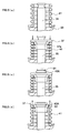
- the fuel inlet valve 20 shown in FIG. 3 (a) to (b) is assembled using the spring seat 37, a C-ring 40A that serves as the fastener 40, the valve body 33 and the valve piston 35, which are respectively shown in FIG. 4(a) to (d) . That is, first, as shown in FIG. 5(a) , the valve piston 35 is inserted into the valve body 33, and the spring 41 is disposed on the upper surface of the valve body 33. Next, as shown in FIG. 5(b) , the valve piston 35 is inserted or press-inserted into the inside of the open portion 37a of the spring seat 37 such that the spring 41 is pushed and compressed. In this state, as shown in FIG.
- the C-ring 40A is caused to lock to the groove portion 51 of the valve piston 35 and, thereafter, as shown in FIG. 5(d) , the spring seat 37 is energized by the spring 41 such that the C-ring 40A is caused to lock to the step portion 53 of the spring seat 37. Assembled in this manner, the spring seat 37 is fixed to the valve piston 35.
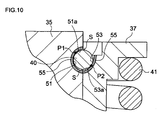
- the clearance S is disposed between the fastener 40 and at least one of the edge portion 51a of the groove portion 51 of the valve piston 35 on the energizing direction side of the spring 41 (the opposite side of the collar portion of the valve piston 35) and the edge portion 53a of the step portion 53 of the spring seat 37 on the opposite side of the energizing direction of the spring 41 (the collar portion side of the valve piston 35), whereby shear force that acts on the fastener 40 is reduced and damage to the fastener 40 is prevented.
- a contact portion P1 between the groove portion 51 of the valve piston 35 and the fastener 40 and a contact portion P2 between the step portion 53 of the spring seat 37 and the fastener 40 are configured such that they are connected in a diagonal direction with respect to the energizing direction of the spring 41.
- the clearance S is respectively disposed between the fastener 40 and the edge portion 51a of the groove portion 51 of the valve piston 35 on the energizing direction side of the spring 41 (the upper side in the drawing) and between the fastener 40 and the edge portion 53a of the step portion 53 of the spring seat 37 on the opposite side of the energizing direction of the spring 41 (the lower side in the drawing).
- the force that acts on the fastener 40 from the spring seat 37 resulting from the energizing force of the spring 41 and the force that acts on the fastener 40 from the valve piston 35 by the downward pushing force of the valve piston 35 resulting from the fuel pressure inside the fuel reservoir chamber act in diagonal directions, and the forces that act on the fastener 40 are changed from a shearing direction to a compressing direction. Additionally, usually, if they are the same material, the allowable compressive stress is higher than the allowable shear stress, so the durability of the fastener 40 becomes improved.
- FIG. 7 (a) is an example where the clearance S is disposed only between the fastener 40 and the edge portion 51a of the groove portion 51 of the valve piston 35 on the energizing direction side of the spring 41 (the upper side in the drawing).
- the force that acts on the fastener 40 from the spring seat 37 and the force that acts on the fastener 40 from the valve piston 35 can be caused to act in diagonal directions. Consequently, the forces that act on the fastener 40 are changed from a shearing direction to a compressing direction, shear force that acts on the fastener 40 can be reduced, and the durability of the fastener 40 can be improved.
- FIG. 7(b) is an example where the clearance S is disposed only between the fastener 40 and the edge portion 53a of the step portion 53 of the spring seat 37 on the opposite side of the energizing direction of the spring 41 (the lower side in the drawing).
- the force that acts on the fastener 40 from the spring seat 37 and the force that acts on the fastener 40 from the valve piston 35 can be caused to act in diagonal directions. Consequently, the forces that act on the fastener 40 are changed from a shearing direction to a compressing direction, shear force that acts on the fastener 40 can be reduced, and the durability of the fastener 40 can be improved.
- the predetermined clearance can be disposed by giving the cross-sectional shape of the groove portion or the step portion a circular arc shape whose diameter is larger than the diameter of the cross section of the fastener and offsetting the center of the circle that draws that circular arc from an outer surface position of the valve piston. That is, when the clearance is to be disposed between the fastener and the predetermined edge portion of the groove portion of the valve piston, as shown in FIG.
- a center position Q of the circle of the circular arc-shaped cross section of the groove portion 51 of the valve piston 35 is offset outward in the outer peripheral direction from an outer surface position of the valve piston 35, whereby the curvature of the groove portion 51 becomes larger than the curvature of the fastener 40 and the predetermined clearance S can be formed.
- the clearance is to be disposed between the fastener and the cut portion of the spring seat, as shown in FIG.
- the center position Q of the circle of the circular arc-shaped cross section of the cut portion 53 of the spring seat 37 is offset in the inside direction of the valve piston 35 from an outer surface position of the valve piston 35, whereby the curvature of the cut portion 53 becomes larger than the curvature of the fastener 40 and the predetermined clearance S can be formed.
- outer surface position of the valve piston means a surface position on the circumferential direction outer side with respect to the axial line of the valve piston and a surface position that exists when it is assumed that that surface position on the circumferential direction outer side extends.
- the predetermined clearance S can also be formed by giving the cross-sectional shapes of the groove portion 51 of the valve piston 35 and the step portion 53 of the spring seat 37 linear shapes.
- the cross-sectional shapes of the groove portion 51 and the step portion 53 are given such linear shapes, the fastener and the valve piston, or the spring seat and the fastener, linearly contact each other, the contact area ends up becoming excessively small, and there is the potential for pressure to become concentrated.
- the cross-sectional shapes are given circular arc shapes because the contact area between the groove portion of the valve piston and the fastener and the contact area between the step portion of the spring seat and the fastener can be ensured as largely as possible and rattling between the valve piston and the spring seat can be prevented.
- a frictional force generating member 55 it is preferable for a frictional force generating member 55 to be intervened between the groove portion 51 of the valve piston 35 and the fastener 40 or between the step portion 53 of the spring seat 37 and the fastener 40.
- this frictional force generating member 55 By intervening this frictional force generating member 55, the contact position between the groove portion 51 of the valve piston 35 or the step portion 53 of the spring seat 37 and the fastener 40, that is, the acting points P1 and P2 of the forces that act on the fastener 40, can be held in positions away from the edges of the groove portion 51 and the step portion 53. Consequently, the force that acts on the fastener 40 from the valve piston 35 and the force that acts on the fastener 40 from the spring seat 37 can be easily caused to act in diagonal directions and shear force that acts on the fastener 40 can be easily reduced.
- the fastener that locks to the groove portion of the valve piston and the step portion of the spring seat is one that can be caused to lock with respect to both the groove portion and the step portion, it is not particularly limited, and a clip member or the like can be used in addition to the aforementioned C-ring.
- a clip member or the like can be used in addition to the aforementioned C-ring.
- the strength of the C-ring can be ensured, and the shape of the C-ring can be returned to its initial shape and reliably locked to the groove portion of the valve piston after the C-ring is widened and the valve piston is inserted during assembly of the fuel inlet valve.
- the high-elasticity alloy include an Ni-Ti alloy and a Co-Cr alloy, but the high-elasticity alloy is not limited to these.
- the valve piston and the spring seat that configure the fuel inlet valve using carburized steel or bearing steel.
- the fuel inlet valve in the fuel supply pump of the present invention employs a fixing method that uses a predetermined fastener as the method of fixing the spring seat to the valve piston, so in terms of the material that configures the spring seat and the valve piston, joining force resulting from welding is no longer called into question. Consequently, the strength of the valve piston and the spring seat can be raised and, even when fuel of an even higher pressure is to be pressure-fed in a large amount, the durability of the fuel supply pump improves and the fuel can be stably pressure-fed. Further, it becomes unnecessary for the fuel inlet valve to be disposed member with a high-strength shim or the like that prevents wear of the spring seat, the number of parts can be reduced, and assembly efficiency can be improved.
- the fuel outlet valve 22 shown in FIG. 2 is disposed on the side of the fuel pressurization chamber 14 in the cylindrical space 11b of the pump housing 11 and is a part for delivering the fuel that has been pressurized to a high pressure to the common rail and the like.
- a ball valve 61 is always energized in a valve closing direction by a spring 63 and, when the plunger 13 is pushed up by the cam 21 and the inside of the fuel pressurization chamber 14 reaches a high pressure, the fuel outlet valve 22 can be opened by the pressure of the fuel and allow the fuel to pass therethrough.
- the fuel supply pump of the present invention that has been described up to now can be suitably used as a fuel supply pump that is used in an accumulator fuel injection system with a pressure amplifying piston (APCRS) that further amplifies, with a pressure amplifying piston, the pressure of high pressure fuel that has been supplied from a pressure accumulator (common rail) and thereafter injects that fuel from injectors.
- APCRS pressure amplifying piston
- FIG. 11 shows a configuration example of an APCRS.
- This APCRS is configured by a fuel tank 62, the fuel supply pump 1 that pressurizes the fuel inside the fuel tank 62 to a high pressure and pressure-feeds the high pressure fuel, a pressure accumulator (common rail) 66 for pressure-accumulating the high pressure fuel that has been pressure-fed from this fuel supply pump 1, pressure amplifying devices (pressure amplifying pistons) 68 for further amplifying the pressure of the fuel that has been pressure-accumulated by the common rail 66, and injectors 70.
- a fuel tank 62 the fuel supply pump 1 that pressurizes the fuel inside the fuel tank 62 to a high pressure and pressure-feeds the high pressure fuel
- a pressure accumulator (common rail) 66 for pressure-accumulating the high pressure fuel that has been pressure-fed from this fuel supply pump
- pressure amplifying devices pressure amplifying pistons
- the configuration of the common rail 66 is not particularly limited, and a publicly known configuration can be used.
- the plural injectors 70 are connected to the common rail 66, the fuel that has been pressurized to a high pressure by the fuel supply pump 1 is supplied equally with respect to all of the injectors 70, and the injectors 70 are controlled such that the injectors 70 can be caused to inject the fuel at a desired injection timing to an internal combustion engine (not shown). Because the APCRS is disposed with this common rail 66, the fuel can be injected to the engine via the injectors 70 at an injection pressure commensurate with the number of rotations without the rotation of the pump directly affecting the injection pressure.
- a pressure detector (not shown) is connected to the common rail 66, and a pressure-detection signal obtained by this pressure detector is sent to an electronic control unit (ECU: Electrical Controlling Unit). Additionally, the ECU receives the pressure-detection signal from the pressure detector and controls an electromagnetic control valve (not shown) similarly disposed in the common rail 66 such that the common rail pressure becomes a predetermined pressure.
- ECU Electrical Controlling Unit
- each of the pressure amplifying devices can be given a configuration which, as exemplified in FIG. 11 , includes a cylinder 75, a mechanical piston (pressure amplifying piston) 74, a pressure reception chamber 78, a pressurization chamber 79, an electromagnetic valve 80 and a circulation path 77, with a pressure receiver 72 and a pressurizer 76 whose area is relatively smaller than that of the pressure receiver 72 being disposed in the mechanical piston 74.
- the mechanical piston 74 that is housed inside the cylinder 75 is pushed by fuel that has the common rail pressure in the pressure receiver 72 and moves such that the fuel inside the pressurization chamber 79 is compressed and its pressure is amplified by the pressurizer 76.
- the pressure amplifying device by configuring the pressure amplifying device as a mechanical piston that is disposed with the pressure receiver and the pressurizer whose area is relatively smaller than that of the pressure receiver and considering the stroke amount of the piston, it is possible to efficiently amplify the pressure of the fuel that has the common rail pressure while reducing pressure loss as much as possible. More specifically, the fuel from the common rail (pressure: p1, volume: V1, workload: W1) can be made into even higher pressure fuel (pressure: p2, volume: V2, workload: W2) by the mechanical piston that is disposed with the pressure receiver whose area is relatively large and the pressurizer whose area is relatively small.
- Each of the pressure amplifying devices 68 shown in FIG. 11 uses the fuel that has the common rail pressure in a large amount in order to push the mechanical piston 74, but after pressurization, the fuel is refluxed to the fuel tank 62 via the electromagnetic valve 80. That is, a large portion of the fuel that has the common rail pressure pushes the mechanical piston 74, is thereafter refluxed to the fuel tank 62 via a line 93, for example, and can again be used as high pressure fuel.
- the configuration of the injectors 70 is not particularly limited and can, as exemplified in FIG. 11 , be given a configuration that is disposed with a nozzle body 103 that includes a seat surface 102 on which a needle valve body 101 sits and an injection hole 73 that is formed further on the downstream side than the valve body abutment portion of this seat surface 102, with the ejector 70 guiding, to the injector hole 73, fuel that is supplied from the upstream side of the seat surface 102 when the needle valve body 101 lifts.
- the needle valve body 101 is always energized toward the seat surface 102 by a spring 104 or the like, and the needle valve body 101 can be configured as an electromagnetic valve type that is opened and closed by switching between energization/no energization of a solenoid (not shown).
- a fuel supply pump that can pressure-feed even higher pressure fuel to the common rail in a large amount is required, but when the fuel supply pump is the fuel supply pump of the present invention such as has been described above, the durability of the fuel inlet valve is improved and the fuel supply pump can withstand long-term use even in use in an APCRS. Consequently, even when the fuel supply pump is caused to operate at a high pressure and a high speed over a long period of time, the fuel supply pump can stably supply a large amount of high pressure fuel.
Landscapes
- Engineering & Computer Science (AREA)
- Mechanical Engineering (AREA)
- General Engineering & Computer Science (AREA)
- Chemical & Material Sciences (AREA)
- Combustion & Propulsion (AREA)
- Fuel-Injection Apparatus (AREA)
Applications Claiming Priority (2)
| Application Number | Priority Date | Filing Date | Title |
|---|---|---|---|
| JP2006127448A JP2007297994A (ja) | 2006-05-01 | 2006-05-01 | 燃料供給用ポンプ |
| PCT/JP2007/058697 WO2007129556A1 (ja) | 2006-05-01 | 2007-04-23 | 燃料供給用ポンプ |
Publications (2)
| Publication Number | Publication Date |
|---|---|
| EP2017464A1 true EP2017464A1 (de) | 2009-01-21 |
| EP2017464A4 EP2017464A4 (de) | 2009-09-30 |
Family
ID=38667664
Family Applications (1)
| Application Number | Title | Priority Date | Filing Date |
|---|---|---|---|
| EP07742132A Withdrawn EP2017464A4 (de) | 2006-05-01 | 2007-04-23 | Kraftstoffzufuhrpumpe |
Country Status (4)
| Country | Link |
|---|---|
| US (1) | US20090185923A1 (de) |
| EP (1) | EP2017464A4 (de) |
| JP (1) | JP2007297994A (de) |
| WO (1) | WO2007129556A1 (de) |
Cited By (1)
| Publication number | Priority date | Publication date | Assignee | Title |
|---|---|---|---|---|
| IT201600073402A1 (it) * | 2016-07-13 | 2018-01-13 | Bosch Gmbh Robert | Gruppo pompa per alimentare combustibile, preferibilmente gasolio, ad un motore a combustione interna |
Families Citing this family (10)
| Publication number | Priority date | Publication date | Assignee | Title |
|---|---|---|---|---|
| JP4985476B2 (ja) * | 2008-03-04 | 2012-07-25 | 株式会社デンソー | 燃料供給ポンプの逆止弁 |
| GB0812888D0 (en) * | 2008-07-15 | 2008-08-20 | Delphi Tech Inc | Improvements relating to fuel pumps |
| JP4968274B2 (ja) * | 2009-02-19 | 2012-07-04 | 株式会社デンソー | 燃料供給ポンプ |
| JP2011214709A (ja) * | 2010-04-02 | 2011-10-27 | Nippon Soken Inc | 開閉弁およびそれを用いた燃料噴射ポンプ |
| DE102010035457A1 (de) * | 2010-08-26 | 2012-03-01 | Robert Bosch Gmbh | Ventilanordnung, Anschlussplatte für eine hydrostatische Kolbenmaschine und hydrostatische Kolbenmaschine |
| JP5847551B2 (ja) * | 2011-11-17 | 2016-01-27 | 株式会社エフ・シー・シー | クラッチ装置 |
| DE102018108406A1 (de) * | 2017-06-22 | 2018-12-27 | Denso Corporation | Hochdruckkraftstoffpumpe und Kraftstoffversorgungssystem |
| CN112922827A (zh) * | 2021-04-21 | 2021-06-08 | 烟台杰瑞石油装备技术有限公司 | 凡尔弹簧座套、阀门组件和柱塞泵 |
| US12270395B1 (en) * | 2024-05-08 | 2025-04-08 | Nebojša Dimitrijević | Piston pump and method of manufacturing the same |
| WO2025233736A1 (en) * | 2024-05-08 | 2025-11-13 | Dimitrijevic Nebojsa | Piston pump |
Family Cites Families (14)
| Publication number | Priority date | Publication date | Assignee | Title |
|---|---|---|---|---|
| US2065794A (en) * | 1934-10-08 | 1936-12-29 | Thompson Prod Inc | Valve spring retainer lock |
| US2314059A (en) * | 1941-07-15 | 1943-03-16 | Wright Aeronautical Corp | Valve lock |
| US2841128A (en) * | 1955-07-13 | 1958-07-01 | Skf Ind Inc | Cage for endwise assembly of balls on valve stems |
| US3021593A (en) * | 1958-05-05 | 1962-02-20 | Walter F Cousino | Method of making metal rings |
| US3762382A (en) * | 1971-06-18 | 1973-10-02 | A Anderson | Valve |
| US3938484A (en) * | 1974-05-20 | 1976-02-17 | Teves-Thompson Gmbh | Valve stem retainer |
| JPH02118104U (de) * | 1989-03-09 | 1990-09-21 | ||
| DE4230022A1 (de) * | 1992-09-10 | 1994-03-17 | Leybold Ag | Schnüffler für Lecksucher |
| CA2108530A1 (en) * | 1993-08-13 | 1995-02-14 | George Hoving Iii | Valve lock |
| JPH09317417A (ja) * | 1996-05-31 | 1997-12-09 | Suzuki Motor Corp | エンジンのバルブ装置 |
| JP2003329151A (ja) * | 2002-05-16 | 2003-11-19 | Denso Corp | バルブ開閉装置およびそのバルブ開閉装置を用いた燃料噴射ポンプ |
| JP2004060616A (ja) * | 2002-07-31 | 2004-02-26 | Fuji Oozx Inc | 内燃機関用動弁装置及びそのエンジンバルブへの組付け方法並びに取外し方法 |
| JP2004211580A (ja) | 2002-12-27 | 2004-07-29 | Bosch Automotive Systems Corp | 大流量燃料用バルブおよびそれを備えた燃料供給用ポンプ |
| DE10346211A1 (de) * | 2003-05-22 | 2004-12-09 | Robert Bosch Gmbh | Rückschlagventil, insbesondere für eine Hochdruckpumpe einer Kraftstoffeinspritzeinrichtung für eine Brennkraftmaschine |
-
2006
- 2006-05-01 JP JP2006127448A patent/JP2007297994A/ja active Pending
-
2007
- 2007-04-23 US US12/299,231 patent/US20090185923A1/en not_active Abandoned
- 2007-04-23 WO PCT/JP2007/058697 patent/WO2007129556A1/ja not_active Ceased
- 2007-04-23 EP EP07742132A patent/EP2017464A4/de not_active Withdrawn
Cited By (1)
| Publication number | Priority date | Publication date | Assignee | Title |
|---|---|---|---|---|
| IT201600073402A1 (it) * | 2016-07-13 | 2018-01-13 | Bosch Gmbh Robert | Gruppo pompa per alimentare combustibile, preferibilmente gasolio, ad un motore a combustione interna |
Also Published As
| Publication number | Publication date |
|---|---|
| US20090185923A1 (en) | 2009-07-23 |
| WO2007129556A1 (ja) | 2007-11-15 |
| EP2017464A4 (de) | 2009-09-30 |
| JP2007297994A (ja) | 2007-11-15 |
Similar Documents
| Publication | Publication Date | Title |
|---|---|---|
| EP2017464A1 (de) | Kraftstoffzufuhrpumpe | |
| US7497157B2 (en) | Fuel supply pump and tappet structural body | |
| JP4453028B2 (ja) | 高圧燃料ポンプ | |
| EP1892410B1 (de) | Kraftstoffzufuhrpumpe und stösselstruktur | |
| EP2507505B1 (de) | Verkehrsschienenkraftstoffpumpe mit kombinierten entladungs- und überdruckentlastungsventilen | |
| JP4172422B2 (ja) | 燃料噴射ポンプ | |
| US7080631B2 (en) | Safety fuel injection pump | |
| US7950373B2 (en) | Check valve with separate spherical spring guide | |
| EP1990531A1 (de) | Kraftstoffeinspritzsystem für verbrennungsmotor | |
| EP2031286A1 (de) | Elektromagnetisches proportionalregelventil zur durchflussmengensteuerung und brennstoffförderpumpe | |
| US7513756B2 (en) | Fuel supply pump and tappet structure body | |
| WO2004040121A1 (ja) | 燃料供給用ポンプおよびタペット構造体 | |
| JP2010112304A (ja) | 燃料供給ポンプ | |
| KR20060108750A (ko) | 연료공급용 펌프 | |
| CN100473821C (zh) | 具有柱塞的燃油泵及使用这种燃油泵的燃油供应系统 | |
| JP2010180783A (ja) | 燃料供給装置 | |
| EP4286680A1 (de) | Elektromagnetischer ventilmechanismus und kraftstoffpumpe | |
| JP2007303430A (ja) | 燃料供給用ポンプ | |
| JP2004324546A (ja) | 燃料供給用ポンプ | |
| JP2010121452A (ja) | 燃料供給ポンプ | |
| WO2016111814A1 (en) | High pressure diesel fuel pump pumping element | |
| JP2020060110A (ja) | 注水ポンプ | |
| JP2004324535A (ja) | 燃料供給用ポンプおよびタペット構造体 | |
| CN101371032A (zh) | 内燃发动机的燃料喷射系统 | |
| JP2010077911A (ja) | 蓄圧式燃料供給装置及びその制御方法 |
Legal Events
| Date | Code | Title | Description |
|---|---|---|---|
| PUAI | Public reference made under article 153(3) epc to a published international application that has entered the european phase |
Free format text: ORIGINAL CODE: 0009012 |
|
| 17P | Request for examination filed |
Effective date: 20081201 |
|
| AK | Designated contracting states |
Kind code of ref document: A1 Designated state(s): AT BE BG CH CY CZ DE DK EE ES FI FR GB GR HU IE IS IT LI LT LU LV MC MT NL PL PT RO SE SI SK TR |
|
| AX | Request for extension of the european patent |
Extension state: AL BA HR MK RS |
|
| RBV | Designated contracting states (corrected) |
Designated state(s): DE FR GB |
|
| A4 | Supplementary search report drawn up and despatched |
Effective date: 20090827 |
|
| RIC1 | Information provided on ipc code assigned before grant |
Ipc: F04B 53/10 20060101ALI20090821BHEP Ipc: F02M 59/46 20060101AFI20090821BHEP |
|
| 17Q | First examination report despatched |
Effective date: 20091028 |
|
| STAA | Information on the status of an ep patent application or granted ep patent |
Free format text: STATUS: THE APPLICATION IS DEEMED TO BE WITHDRAWN |
|
| 18D | Application deemed to be withdrawn |
Effective date: 20100309 |