EP2017470A1 - Dispositif de generation d'electricite d'origine eolienne, procede de controle du dispositif de generation d'electricite d'origine eolienne et programme informatique - Google Patents
Dispositif de generation d'electricite d'origine eolienne, procede de controle du dispositif de generation d'electricite d'origine eolienne et programme informatique Download PDFInfo
- Publication number
- EP2017470A1 EP2017470A1 EP06745763A EP06745763A EP2017470A1 EP 2017470 A1 EP2017470 A1 EP 2017470A1 EP 06745763 A EP06745763 A EP 06745763A EP 06745763 A EP06745763 A EP 06745763A EP 2017470 A1 EP2017470 A1 EP 2017470A1
- Authority
- EP
- European Patent Office
- Prior art keywords
- flying object
- generation device
- power generation
- wind power
- blades
- Prior art date
- Legal status (The legal status is an assumption and is not a legal conclusion. Google has not performed a legal analysis and makes no representation as to the accuracy of the status listed.)
- Withdrawn
Links
Images




Classifications
-
- F—MECHANICAL ENGINEERING; LIGHTING; HEATING; WEAPONS; BLASTING
- F03—MACHINES OR ENGINES FOR LIQUIDS; WIND, SPRING, OR WEIGHT MOTORS; PRODUCING MECHANICAL POWER OR A REACTIVE PROPULSIVE THRUST, NOT OTHERWISE PROVIDED FOR
- F03D—WIND MOTORS
- F03D7/00—Controlling wind motors
- F03D7/02—Controlling wind motors the wind motors having rotation axis substantially parallel to the air flow entering the rotor
- F03D7/04—Automatic control; Regulation
- F03D7/042—Automatic control; Regulation by means of an electrical or electronic controller
-
- F—MECHANICAL ENGINEERING; LIGHTING; HEATING; WEAPONS; BLASTING
- F03—MACHINES OR ENGINES FOR LIQUIDS; WIND, SPRING, OR WEIGHT MOTORS; PRODUCING MECHANICAL POWER OR A REACTIVE PROPULSIVE THRUST, NOT OTHERWISE PROVIDED FOR
- F03D—WIND MOTORS
- F03D17/00—Monitoring or testing of wind motors, e.g. diagnostics
-
- F—MECHANICAL ENGINEERING; LIGHTING; HEATING; WEAPONS; BLASTING
- F03—MACHINES OR ENGINES FOR LIQUIDS; WIND, SPRING, OR WEIGHT MOTORS; PRODUCING MECHANICAL POWER OR A REACTIVE PROPULSIVE THRUST, NOT OTHERWISE PROVIDED FOR
- F03D—WIND MOTORS
- F03D7/00—Controlling wind motors
- F03D7/02—Controlling wind motors the wind motors having rotation axis substantially parallel to the air flow entering the rotor
- F03D7/0264—Controlling wind motors the wind motors having rotation axis substantially parallel to the air flow entering the rotor for stopping; controlling in emergency situations
-
- F—MECHANICAL ENGINEERING; LIGHTING; HEATING; WEAPONS; BLASTING
- F05—INDEXING SCHEMES RELATING TO ENGINES OR PUMPS IN VARIOUS SUBCLASSES OF CLASSES F01-F04
- F05B—INDEXING SCHEME RELATING TO WIND, SPRING, WEIGHT, INERTIA OR LIKE MOTORS, TO MACHINES OR ENGINES FOR LIQUIDS COVERED BY SUBCLASSES F03B, F03D AND F03G
- F05B2260/00—Function
- F05B2260/82—Forecasts
- F05B2260/821—Parameter estimation or prediction
-
- F—MECHANICAL ENGINEERING; LIGHTING; HEATING; WEAPONS; BLASTING
- F05—INDEXING SCHEMES RELATING TO ENGINES OR PUMPS IN VARIOUS SUBCLASSES OF CLASSES F01-F04
- F05B—INDEXING SCHEME RELATING TO WIND, SPRING, WEIGHT, INERTIA OR LIKE MOTORS, TO MACHINES OR ENGINES FOR LIQUIDS COVERED BY SUBCLASSES F03B, F03D AND F03G
- F05B2270/00—Control
- F05B2270/10—Purpose of the control system
- F05B2270/107—Purpose of the control system to cope with emergencies
-
- F—MECHANICAL ENGINEERING; LIGHTING; HEATING; WEAPONS; BLASTING
- F05—INDEXING SCHEMES RELATING TO ENGINES OR PUMPS IN VARIOUS SUBCLASSES OF CLASSES F01-F04
- F05B—INDEXING SCHEME RELATING TO WIND, SPRING, WEIGHT, INERTIA OR LIKE MOTORS, TO MACHINES OR ENGINES FOR LIQUIDS COVERED BY SUBCLASSES F03B, F03D AND F03G
- F05B2270/00—Control
- F05B2270/80—Devices generating input signals, e.g. transducers, sensors, cameras or strain gauges
- F05B2270/804—Optical devices
- F05B2270/8041—Cameras
-
- F—MECHANICAL ENGINEERING; LIGHTING; HEATING; WEAPONS; BLASTING
- F05—INDEXING SCHEMES RELATING TO ENGINES OR PUMPS IN VARIOUS SUBCLASSES OF CLASSES F01-F04
- F05B—INDEXING SCHEME RELATING TO WIND, SPRING, WEIGHT, INERTIA OR LIKE MOTORS, TO MACHINES OR ENGINES FOR LIQUIDS COVERED BY SUBCLASSES F03B, F03D AND F03G
- F05B2270/00—Control
- F05B2270/80—Devices generating input signals, e.g. transducers, sensors, cameras or strain gauges
- F05B2270/805—Radars
-
- Y—GENERAL TAGGING OF NEW TECHNOLOGICAL DEVELOPMENTS; GENERAL TAGGING OF CROSS-SECTIONAL TECHNOLOGIES SPANNING OVER SEVERAL SECTIONS OF THE IPC; TECHNICAL SUBJECTS COVERED BY FORMER USPC CROSS-REFERENCE ART COLLECTIONS [XRACs] AND DIGESTS
- Y02—TECHNOLOGIES OR APPLICATIONS FOR MITIGATION OR ADAPTATION AGAINST CLIMATE CHANGE
- Y02E—REDUCTION OF GREENHOUSE GAS [GHG] EMISSIONS, RELATED TO ENERGY GENERATION, TRANSMISSION OR DISTRIBUTION
- Y02E10/00—Energy generation through renewable energy sources
- Y02E10/70—Wind energy
- Y02E10/72—Wind turbines with rotation axis in wind direction
Definitions
- the present invention relates to a technology to avoid occurrence that a flying object collides against a blade when the flying object (mainly, birds) is approaching to wind power generation device, and technologies relating thereto.
- a Doppler sodar Doppler sonic radar
- the sonic wave collides against particles such as water vapor, dusts or the like contained in the wind in the air and reflects.
- the reflection wave is caught with a large cylindrical body and wind speed thereof is calculated based on the reflection wave modulated due to a Doppler effect. It is possible to calculate a wind direction by using about three pieces of cylindrical bodies for receiving and transmitting sonic waves and varying the inclination and the direction thereof respectively.
- a laser Doppler radiates laser light and receives scattered light from dusts floating in the air. It is a technology to determine a wind speed and a wind direction by studying the frequency displacement amount of the light since the received light is affected by the Doppler effect due to an influence of the wind. As a technology to measure the wind direction and the wind speed of a planned area for establishing a windmill for wind power generation, there is a technology disclosed in Patent Document 1, for instance.
- Patent Document 1 Japanese Patent Application Laid-open No. 2004-101265
- the wind power generation device is designed conforming to the wind condition of the place where the device is installed.
- the wind power generation device is provided with the following "limitation adjustment mechanism". That is, provided is a mechanism to select a blade angle so as to reduce rotation efficiency to the wind or so as to relieve the wind when a wind speed equal to or greater than that prescribed is expected or detected by measuring the wind speed or obtaining forecast information concerning the weather.
- the wind power generation device is installed by selecting a place where wind blows stably. At a place far from an urban district, a large-scale wind power generation device is often installed in plural number of units. At a place where wind conditions are favorable, a wind farm with several ten or several hundred units of the wind power generation devices is also developed.
- the wind power generation device is upsizing.
- a typical large-scale wind power generation device is installed on a tower about 30 to 80 meters in height, and since the length of the blades of such a wind power generation device is 20 to 50 meters, the highest position is as tall as 130 meters from the ground.
- such a height sometimes corresponds to a place where birds fly, which live in the neighborhood where the wind power generation device is installed or corresponds to a height for cruising flight of migratory birds.
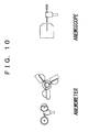
- the device is provided with an anemometer and an anemoscope as shown in FIG. 10 , but these are only for an ex post measurement, and a flying object blown off by a strong wind collides against a blade, which may result in breakage of the blade.
- a problem to be solved by the present invention is to provide a technology enabling to reduce breakage of the blade caused by the flying object or to reduce the bird strike.
- an object of the inventions described in claims 1 to 4 is to provide a wind power generation device enabling to reduce the breakage of the blade caused by the flying object or to reduce the bird strike.
- another object of the inventions described in claims 5 to 7 is to provide a control process for the wind power generation device enabling to reduce the breakage of the blade caused by the flying object or to reduce the bird strike.
- Still another object of the inventions described in claims 8 to 10 is to provide a control program for the wind power generation device enabling to reduce the breakage of the blade caused by the flying object or to reduce the bird strike.
- Yet another object of the inventions described in claims 11 to 13 is, in addition to the object of the above-described inventions, to provide a technology relating to the wind power generation device enabling to reduce breakage accidents of the blade by a gust.
- An invention described in claim 1 relates to a wind power generation device provided with a tower set up on the ground, a nacelle fixed on the tower, a plurality of blades rotatably fixed to the nacelle via a hub, an obstacle search device capable of detecting a flying object existing in front, on the windward side, and a blade angle controller to control the change in angle of the blade including a rotation stop position, in which when the obstacle search device detects the flying object, the blade angle controller controls to change the blade to the rotation stop position.
- the word “flying objects” includes an object blown off by the wind, other than a living creature such as birds.
- the obstacle search device is a device to oscillate a sonic wave or an electromagnetic wave, and to ascertain the presence of the flying object by seizing the reflection waves, a device to confirm the presence of the flying object based on an image pickup or image analysis, or a device to detect a living creature such as birds or the like by thermal detection, etc.
- it is used in combination of an anemoscope. Note that since the wind power generation device is designed to face toward the windward side, it is recommendable to allow the obstacle search device to move in synchronization with the wind power generation device by, for instance, installing it in the hub of the wind power generation device.
- the rotation stop position designates a position at which the blades do not rotate even when the blades undergo wind, and it is typically a feathering position or sufficient deceleration of a rotational speed. It also includes the case of using a brake secondarily to stop the rotation of the blade or the case of stopping the rotation of the blade using the brake as a main means.
- a means to control braking of the rotation includes a pitch controller which changes pitch angles of all blades and a stall controller which allows to select a blade shape and the pitch angle so as to lose lift, and at the same time, changes the direction of the blade top to 90° to serve as a brake when to stop.
- the wind power generation device is often formed to allow it to select a position to reduce rotational efficiency according to a strong wind other than the feathering position. This is because if the rotation is completely stopped, it will take a long time to resume the operation, but in the case of sufficient deceleration, it is easy to resume the operation, which makes it possible to reduce power-generation loss.
- the wind power generation device relating to the present claim generates electricity by rotation of the blades when undergoing wind.
- the obstacle search device is supposed to detect a flying object on the windward side.
- the blade angle controller controls to change the blades to the rotation stop position.
- the rotation of the blades stops or decelerates sufficiently.
- the possibility of the bird to avoid the blade by itself is increased.
- the blade is often formed in a slim shape with about three sheets of the blade fixed in a radial form from the hub, it is possible to lower the possibility of collision against the blade even when the flying object is only an object other than birds.
- An invention described in claim 2 also relates to a wind power generation device provided with a tower set up on the ground, a nacelle fixed on the tower, a plurality of blades rotatably fixed to the nacelle via a hub, an obstacle search device capable of detecting a flying object in front, on the windward side, and a blade angle controller to control change in angle of the blades including a rotation stop position, in which the obstacle search device searches for the flying object continuously, and when the flying object is determined to be approaching based on the continuous search, the blade angle controller controls to change the blades to the rotation stop position.
- the obstacle search device is provided with functions to store data concerning a flying object for a prescribed period of time or to conduct comparative computation comparing with just previous data for the purpose of searching for the flying object continuously.
- the flying object is a bird, it sometimes flies with a speed faster than the wind speed.
- a point different from the invention in claim 1 is to control to change the blades to the rotation stop position only when the flying object approaches. Since the present invention determines whether or not the flying object is approaching, when it detects the flying object once but determines that it will not approach, the possibility of collision is low and the device can continue generation of electricity without stopping it in vain. Note that the wind power generation device is effective for the cases when the movement of the flying object is very fast, or when it is unpredictable with the wind power generation device described in claim 1 as for whether or not the flying object is approaching or whether or not the possibility of collision is high, even by continuous detection.
- the invention described in claim 3 is to limit the wind power generation device according to any one of claim 1 and claim 2. That is, the wind power generation device further includes an arrival time calculator to calculate an estimated arrival time of the flying object detected by the obstacle search device, in which the blade angle controller controls to change the blade angle to the rotation stop position before the estimated arrival time is reached.
- the arrival time calculator continuously searches for the flying object and estimates the arrival time of the flying object from speed of sound and distance when the obstacle search device uses a sonic wave or an electromagnetic wave. In other words, it is necessary to search for the flying object being away in the distance sufficiently far to ensure the time (for instance, about 5 seconds) required for the blade angle controller to change the blade angle so as to stop the rotation of the blades when the device detects approaching of the flying object and determines to stop rotation.
- the arrival time calculator calculates an estimated arrival time of the flying object detected by the obstacle search device. Then, the blade angle controller controls to change a blade angle to the rotation stop position before the estimated arrival time is reached. As a result, it is possible to increase the possibility of preventing breakage of the blade by the flying object or bird strike in advance.
- the invention described in claim 4 is to limit the wind power generation device according to any one of claim 1 to claim 3. That is, it relates to the wind power generation device in which the obstacle search device can perform a wide-angle search and a narrow-angle search, and carries out the wide-angle search until the flying object is detected. When the flying object is detected, the obstacle search device shifts to the narrow-angle search taking aim at the flying object, and determines whether or not the flying object is approaching.
- the angle at which the obstacle search device can search is as wide as possible.
- the speed of wind is fast, and the speed of the flying object is also fast, an error in seizing continuous movement of the flying object and in calculating an estimated arrival time increases in the case of carrying out the wide-angle search. Therefore, adopted is a configuration to change the obstacle search device into the narrow-angle search taking aim at the flying object so as to be able to determine whether or not the flying object is approaching when the flying object is detected.
- the invention described in claim 5 relates to a method of controlling a wind power generation device provided with a tower set up on the ground, a nacelle fixed on the tower, and a plurality of blades rotatably fixed to the nacelle via a hub. That is, the method of controlling the wind power generation device includes: a flying object detecting step to detect a flying object existing in front, on the windward side; and a rotation stopping step to control to change the blades to a rotation stop position when the flying object is detected by the flying object detecting step.
- the invention described in claim 6 relates to a method of controlling a wind power generation device provided with a tower set up on the ground, a nacelle fixed on the tower, and a plurality of blades rotatably fixed to the nacelle via a hub. That is, the method of controlling the wind power generation device includes: a flying object detecting step to continuously search for a flying object; a flying object approach detecting step to determine whether or not the flying object is approaching when the flying object is detected by the flying object detecting step; and a rotation stopping step to change the blades to a rotation stop position when the flying object approach detecting step determines the approach of the flying object.
- the invention described in claim 7 is to limit the method of controlling the wind power generation device according to any one of claim 5 and claim 6. That is, the method of controlling the wind power generation device further includes: an arrival time calculating step to calculate an estimated arrival time of the flying object when the flying object is detected by the flying object detecting step, in which the rotation stopping step is to change the blades to the rotation stop position before the estimated arrival time is reached.
- the invention described in claim 8 relates to a control program of a wind power generation device provided with a tower set up on the ground, a nacelle fixed on the tower, and a plurality of blades rotatably fixed to the nacelle via a hub.
- the control program is a computer program forcing a control computer of the wind power generation device to execute a flying object detecting step to detect a flying object, and a rotation stopping step to control to change the blades to a rotation stop position when the flying object is detected by the flying object detecting step.
- the invention described in claim 9 also relates to a control program of a wind power generation device provided with a tower set up on the ground, a nacelle fixed on the tower, and a plurality of blades rotatably fixed to the nacelle via a hub.
- the control program is a computer program forcing a control computer of the wind power generation device to execute: a flying object detecting step to search for a flying object continuously; a flying object approach detecting step to determine whether or not the flying object is approaching when the flying object is detected by the flying object detecting step; and a rotation stopping step to change the blades to a rotation stop position when the flying object approach detecting step determines the approach of the flying object.
- the invention described in claim 10 is to limit the computer program according to any one of claim 8 and claim 9. That is, the computer program further includes an arrival time calculating step to calculate an estimated arrival time of the flying object when the flying object is detected by the flying object detecting step, in which the rotation stopping step is to change the blades to the rotation stop position before the estimated arrival time is reached.
- the invention described in claim 11 is to limit the wind power generation device according to any one of claim 1 to claim 4. That is, the present invention relates to the wind power generation device in which the nacelle or the hub includes a Doppler anemometer capable of measuring the frontward wind speed by oscillating and receiving a sonic wave or an electromagnetic wave, and when the Doppler anemometer detects a wind speed equal to or greater than a prescribed speed, the blade angle controller changes the blade angle so as not to break the blade by the wind speed.
- the nacelle or the hub includes a Doppler anemometer capable of measuring the frontward wind speed by oscillating and receiving a sonic wave or an electromagnetic wave, and when the Doppler anemometer detects a wind speed equal to or greater than a prescribed speed, the blade angle controller changes the blade angle so as not to break the blade by the wind speed.
- the Doppler anemometer is an anemometer oscillating a sonic wave or an electromagnetic wave to calculate a wind speed by measuring the difference in speed based on a Doppler effect of the sonic wave or the electromagnetic wave, which collides with or reflects from a reflector such as a dust or the like contained in the wind.
- the position on which the anemometer is installed is inside the hub, an upper part of the nacelle or in the lateral direction thereof.
- the wind speed on the windward side of the wind power generation device is measured with the Doppler anemometer applying a Doppler effect by oscillating and receiving a sonic wave or an electromagnetic wave.
- the Doppler anemometer detects a wind speed at a prescribed value or more
- the blade angle controller changes the blade angle. For instance, when detecting a wind speed equal to or more than a limited value, the wind is allowed to escape by changing to the feathering so as to reduce damages to the blade or to the tower.
- gust-prevention measures such as change of the blade angle or the like by detecting a gust in advance without necessitating an observation tower.
- the invention described in claim 12 is to limit the method of controlling the wind power generation device according to any one of claim 5, claim 6 and claim 7. That is, the present invention relates to the method of controlling the wind power generation device, in which the wind power generation device includes a Doppler anemometer capable of measuring the frontward wind speed by oscillating and receiving a sonic wave or an electromagnetic wave, and the method of controlling the wind power generation device including: a flying object detecting step to detect the flying object existing in front, on the windward side; and a rotation stopping step to control to change the blades to the rotation stop position when detecting the flying object by the flying object detecting step.
- the wind power generation device includes a Doppler anemometer capable of measuring the frontward wind speed by oscillating and receiving a sonic wave or an electromagnetic wave
- the method of controlling the wind power generation device including: a flying object detecting step to detect the flying object existing in front, on the windward side; and a rotation stopping step to control to change the blades to the rotation stop position when detecting
- the invention described in claim 13 is to limit the computer program according to any one of claim 8, claim 9 and claim 10. That is, the present invention relates to the computer program, in which the wind power generation device further includes a Doppler anemometer capable of measuring the frontward wind speed by oscillating and receiving a sonic wave or an electromagnetic wave, and the computer program forces the control computer of the wind power generation device to execute a flying object detecting step to detect the flying object existing in front, on the windward side; and a rotation stopping step to control to change the blades to the rotation stop position when detecting the flying object by the flying object detecting step.
- the wind power generation device further includes a Doppler anemometer capable of measuring the frontward wind speed by oscillating and receiving a sonic wave or an electromagnetic wave
- the computer program forces the control computer of the wind power generation device to execute a flying object detecting step to detect the flying object existing in front, on the windward side; and a rotation stopping step to control to change the blades to the rotation stop position when detecting the flying
- the computer program relating to claim 8 to claim 10 and claim 13 into a chip it is possible to make the computer program relating to claim 8 to claim 10 and claim 13 into a chip to be a blade control device of the wind power generation device. It is also possible to store it in a recording medium to be provided.
- the recording medium is a medium that can hold a program unable to occupy a space by itself, and, for instance, a flexible disk, a hard disk, a CD-R, an optical magnetic disk (MO), DVD-R or the like can be listed.
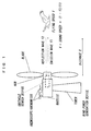
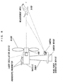
- FIG. 1 is a conceptual view showing a first embodiment
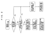
- FIG. 2 is a flow chart showing a control process
- FIG. 3 is a graph showing the wind speed and the amount of electricity generation.
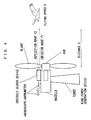
- FIG. 4 is a conceptual view of a second embodiment.
- FIG. 5 is a conceptual view showing image pickup and image analysis.
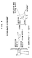
- FIG. 6 is an image view of an emission wave and a reflection wave when a flying object is in presence.
- FIG. 7 is an image view of an emission wave and a reflection wave when the flying object is absence.
- FIG. 8 is a conceptual view showing a third embodiment
- the first embodiment shown in FIG. 1 relates to a wind power generation device including a tower set up on the ground, a nacelle fixed on the tower, a plurality of blades rotatably fixed to the nacelle via a hub, an obstacle search device capable of detecting the flying object in front, on the windward side, and a blade angle controller to control change in the blade angle including a rotation stop position.
- the obstacle search device adopted is not a device to ascertain the presence of the flying object based on the image pickup and the image analysis, but a device to ascertain the presence of the flying object by oscillating a sonic wave or an electromagnetic wave and seizing its reflection wave.
- a thermal detector when used, though it can detect only the flying object such as a living creature like birds having a higher temperature than its surrounding temperature, it has an advantage that at night or under a bad weather such as driving snow, the detection of the flying object can be performed more accurately than the detection with the obstacle search device transmitting a sonic wave or an electromagnetic wave.
- the nacelle is provided with an anemoscope, and by an output obtained from the anemoscope, the wind power generation device faces the windward.
- the obstacle search device is a device that oscillates a sonic wave or an electromagnetic wave (emission wave f1), and ascertains the presence of the flying object by seizing the reflection wave (f2).
- the obstacle search device is disposed in the hub of the wind power generation device and operates in synchronization with the wind power generation device. When the obstacle search device ascertains the presence of the flying object, it is controlled in a manner as shown in a flow chart shown in FIG. 2 .
- FIG. 2 shows an example of the control.
- the wind power generation device generates electricity by rotation of the blades caused by receiving wind.
- the obstacle search device does not detect the flying object on the windward side, it continues the operation.
- the obstacle search device stores data on the flying object for a prescribed period of time or conducts comparison computation with data obtained immediately before by searching the flying object continuously.
- the estimated arrival time of the flying object is calculated from the flying speed V and its distance X and a blade angle controller controls to change the blade to a rotation stop position (feathering). Then, the rotation of the blade is stopped before the estimated arrival time of the flying object.
- the control program described above is included in the blade control device.
- FIG. 3 (FIG. 3)
- FIG. 3 shows a relation between the wind speed and the amount of electricity generation.
- the blades are adjusted so that the wind power generation device can be operated at a rated wind speed.
- the wind speed is at a prescribed speed (cut out wind speed) or higher, the electricity generation is suspended due to the feathering.
- change to the feathering is also executed.
- FIG. 4 (FIG. 4)
- the embodiment shown in FIG. 4 differs from the embodiment shown in FIG. 1 , and the obstacle search device is not embedded in the hub, but it is mounted on the nacelle. When the blades are in rotation, it may disturb the operation of the obstacle search device, but the oscillation timing of a sonic wave or an electromagnetic wave should be controlled so as to avoid the blades in rotation.
- the wind power generation device relating to the embodiments explained above, it becomes possible to provide a wind power generation device capable of reducing collision of the flying object to the blade or bird strike.
- the obstacle search device explained above When the obstacle search device explained above is installed on a wind farm, it is desirable that all wind power generation devices be provided with obstacle search devices. However, in the case that the obstacle search device cannot be provided to every wind power generation device, when the obstacle search device detects an obstacle, control of the blade angle is contrived to be executed even for the device without the obstacle search device. Then, it contributes to reduce collision of the flying object to the blade or bird strike.
- FIG. 5 (FIG. 5)
- the obstacle search device by image pickup and image analysis will be explained further in detail based on FIG. 5 .
- the vertical length in which the flying object can be fallen is assumed to be Y.
- half of a search angle of the obstacle search device within which the obstacle search device can seize the flying object is assumed to be 0.
- the time at which the flying object is first detected is T2
- the search angle at this time is ⁇ 2
- the time taken for the flying object to arrive at the wind power generation device is T1
- the search angle at this time is ⁇ 1
- the distance to which the flying object can arrive in T1 is X
- the flying speed of the flying object is V.
- T ⁇ 1 X / V
- FIG. 6 (FIG. 6)
- FIG. 6 shows how the emission wave (f1) and the reflection wave (f2) are seized in a relation between signals and frequencies when the flying object is in presence. It is an actual example that the reflection wave (f2) is greater than the emission wave (f1) in both signal and frequency.
- FIG. 7 (FIG. 7)
- FIG. 7 shows how the emission wave (f1) and the reflection wave (f3) are seized in the relation between signals and frequencies when the flying object is in absence (in other words, when only wind blows). Although the reflection wave (f2) is greater than the emission wave (f1) in frequency, it does not change so much as when the flying object is in presence.
- control algorithms which store data based on an actual example as shown in FIG. 6 and FIG. 7 , instantaneously execute comparison with stored data and determine whether or not the flying object is approaching.
- FIG. 8 (FIG. 8)
- the embodiment shown in FIG. 8 is not a device to ascertain the presence of the flying object by oscillating a sonic wave or an electromagnetic wave and by seizing its reflection wave, but a device to ascertain the presence of the flying object based on the image pickup and the image analysis is adopted. In other words, it detects the approach of the flying object in a two dimensional plane by irradiating laser beams to fine particles (tracer) mixed in fluid, continuously obtaining their scattered light as an image and determining a traveling distance of the particles.
- This flying object detection device includes a laser-oscillation device embedded in the hub, a ring-shaped camera mover fixed on the tower near the ground and moving around the tower, and a camera fixed on the surrounding of the upper surface of the camera mover to be movable around the tower.
- the camera is a CCD or a C-MOS sensor and photographs a sheet-like laser beam, which a laser-oscillation device emits from below.
- the camera is formed so as to move above the camera mover so that it faces the windward side in synchronization with the nacelle based on the wind direction that the anemoscope/anemometer detects.
- the laser-oscillation device irradiates the sheet-like laser beam toward the windward side of the wind power generation device. Then, the tracer seized by the laser beam irradiated to a flowing field is continuously obtained as photographed image data by the camera. At this time, the timing of photographing by the camera is synchronized with the laser beam by a controller.
- the photographed image data continuously obtained are processed for wind condition analysis with an image processing means of a computer. That is, even when the approach of the flying object is detected by the image analysis, it is possible to prevent, in advance, a breakage accident of the blade caused by gust through controlling a blade angle or the like.
Landscapes
- Engineering & Computer Science (AREA)
- Life Sciences & Earth Sciences (AREA)
- Sustainable Development (AREA)
- Sustainable Energy (AREA)
- Chemical & Material Sciences (AREA)
- Combustion & Propulsion (AREA)
- Mechanical Engineering (AREA)
- General Engineering & Computer Science (AREA)
- Wind Motors (AREA)
Applications Claiming Priority (1)
| Application Number | Priority Date | Filing Date | Title |
|---|---|---|---|
| PCT/JP2006/308835 WO2007129378A1 (fr) | 2006-04-27 | 2006-04-27 | Dispositif de generation d'electricite d'origine eolienne, procede de controle du dispositif de generation d'electricite d'origine eolienne et programme informatique |
Publications (1)
| Publication Number | Publication Date |
|---|---|
| EP2017470A1 true EP2017470A1 (fr) | 2009-01-21 |
Family
ID=38667500
Family Applications (1)
| Application Number | Title | Priority Date | Filing Date |
|---|---|---|---|
| EP06745763A Withdrawn EP2017470A1 (fr) | 2006-04-27 | 2006-04-27 | Dispositif de generation d'electricite d'origine eolienne, procede de controle du dispositif de generation d'electricite d'origine eolienne et programme informatique |
Country Status (3)
| Country | Link |
|---|---|
| US (1) | US20090185900A1 (fr) |
| EP (1) | EP2017470A1 (fr) |
| WO (1) | WO2007129378A1 (fr) |
Cited By (11)
| Publication number | Priority date | Publication date | Assignee | Title |
|---|---|---|---|---|
| DE102008018880A1 (de) * | 2008-04-14 | 2009-10-15 | Carl Zeiss Optronics Gmbh | Überwachungsverfahren und -vorrichtung für Windkraftanlagen, Gebäude mit transparenten Bereichen, Start- und Landebahnen und/oder Flugkorridore von Flughäfen |
| US20130050400A1 (en) * | 2011-08-31 | 2013-02-28 | Henrik Stiesdal | Arrangement and Method to Prevent a Collision of a Flying Animal with a Wind Turbine |
| WO2013053361A3 (fr) * | 2011-10-10 | 2013-06-06 | Vestas Wind Systems A/S | Détection radar des conditions météorologiques destinée à une éolienne |
| US9416769B2 (en) | 2011-08-31 | 2016-08-16 | Siemens Aktiengesellschaft | Method to control the operation of a wind turbine |
| WO2016200270A1 (fr) * | 2015-06-08 | 2016-12-15 | Sintef Energi As | Système et procédé de prévention de collisions entre des pales d'éolienne et des objets volants |
| WO2017132654A1 (fr) * | 2016-01-28 | 2017-08-03 | General Electric Company | Système et procédé permettant d'améliorer la disponibilité du signal de capteur lidar sur une turbine éolienne |
| EP3183602A4 (fr) * | 2014-08-21 | 2018-06-20 | IdentiFlight International, LLC | Réseau d'imagerie pour détection et identification d'oiseaux ou de chauves-souris |
| WO2022003213A1 (fr) * | 2020-06-29 | 2022-01-06 | 3D Observer Project, S.L. | Système et méthode pour détecter l'avifaune dans des parcs éolients |
| EP4296506A1 (fr) * | 2022-06-23 | 2023-12-27 | Wobben Properties GmbH | Procédé de commande d'une éolienne destiné à la protection des oiseaux et des chauves-souris |
| WO2025077983A1 (fr) * | 2023-10-10 | 2025-04-17 | Vestas Wind Systems A/S | Parc éolien doté de mesures de prévention de collision d'oiseaux |
| WO2025077982A1 (fr) * | 2023-10-10 | 2025-04-17 | Vestas Wind Systems A/S | Éolienne avec changement de mode de fonctionnement pour empêcher une collision avec les oiseaux |
Families Citing this family (23)
| Publication number | Priority date | Publication date | Assignee | Title |
|---|---|---|---|---|
| US8482613B2 (en) * | 2007-09-10 | 2013-07-09 | John Kempf | Apparatus and method for photographing birds |
| US7934905B2 (en) * | 2007-11-30 | 2011-05-03 | General Electric Company | Wind energy system having an insect sensor |
| JPWO2009102001A1 (ja) * | 2008-02-15 | 2011-06-16 | 東京電力株式会社 | 鳥類探査システム、鳥類探査方法およびコンピュータプログラム |
| JP5059666B2 (ja) * | 2008-03-21 | 2012-10-24 | 東京電力株式会社 | 飛来物検知装置、飛来物検知方法およびコンピュータプログラム |
| BRPI0822913A2 (pt) * | 2008-10-09 | 2015-06-23 | Mitsubishi Heavy Ind Ltd | Gerador de turbina de vento fora da costa e fazenda de vento fora da costa |
| US20110135466A1 (en) * | 2010-01-14 | 2011-06-09 | General Electric Company | System and method for monitoring and controlling wind turbine blade deflection |
| EP2369176A1 (fr) * | 2010-02-24 | 2011-09-28 | Siemens Aktiengesellschaft | Éolienne et procédé pour mesurer l'angle de pas d'une pale de rotor d'éolienne |
| US20110204632A1 (en) * | 2010-02-25 | 2011-08-25 | Skala James A | Synchronous Induced Wind Power Generation System |
| CA2814347A1 (fr) * | 2010-10-19 | 2012-04-26 | Renewable Energy Systems Americas Inc. | Systemes et procedes pour la gestion d'oiseaux pour fermes eoliennes |
| US9115699B2 (en) | 2012-02-28 | 2015-08-25 | General Electric Company | Ultrasonic sound emitting devices for wind turbines |
| US9474265B2 (en) | 2012-11-27 | 2016-10-25 | Elwha Llc | Methods and systems for directing birds away from equipment |
| US9775337B2 (en) | 2012-11-27 | 2017-10-03 | Elwha Llc | Methods and systems for directing birds away from equipment |
| US9125394B2 (en) | 2013-01-30 | 2015-09-08 | General Electric Company | Ultrasonic sound emitting devices for wind turbines |
| US9128184B1 (en) * | 2013-03-14 | 2015-09-08 | Lockheed Martin Corporation | Radar wind turbine |
| JP6149926B2 (ja) * | 2013-03-28 | 2017-06-21 | 日本電気株式会社 | 鳥検知装置、鳥検知システム、鳥検知方法およびプログラム |
| US9706766B2 (en) | 2013-06-25 | 2017-07-18 | General Electric Company | Active systems and methods for producing ultrasonic sound emissions from wind turbines |
| WO2016029135A1 (fr) | 2014-08-21 | 2016-02-25 | Boulder Imaging, Inc. | Systèmes et procédés de détection d'oiseaux |
| US9886864B1 (en) | 2016-02-03 | 2018-02-06 | X Development Llc | Methods for aerial avoidance |
| PL232585B1 (pl) * | 2016-02-13 | 2019-06-28 | Przybycin Michal | Urządzenie rejestrujące kolizje zwierząt latających z elektrowniami wiatrowymi i wskazujące miejsce ich upadku na podłoże |
| US11965486B2 (en) * | 2018-06-21 | 2024-04-23 | Vestas Wind Systems A/S | Wind energy park comprising a wind turbine and an airborne wind energy system |
| US11278021B1 (en) * | 2021-02-24 | 2022-03-22 | Timothy Just | Wildlife deterring windmill |
| US11672243B2 (en) | 2021-02-24 | 2023-06-13 | Timothy Just | Wildlife deterring windmill |
| DK202370493A1 (en) * | 2023-09-27 | 2025-04-10 | Robin Radar Facilities Bv | Systems and methods for reducing risk of avian collision with wind turbines |
Family Cites Families (6)
| Publication number | Priority date | Publication date | Assignee | Title |
|---|---|---|---|---|
| JPH0680868U (ja) * | 1993-04-29 | 1994-11-15 | 靖彦 鴨志田 | 風力発電装置 |
| JP2003021046A (ja) * | 2001-07-09 | 2003-01-24 | Sanyo Electric Co Ltd | 風力発電装置 |
| JP2003148321A (ja) * | 2001-11-16 | 2003-05-21 | Mitsubishi Heavy Ind Ltd | 風力発電装置 |
| JP3774689B2 (ja) | 2002-09-06 | 2006-05-17 | 三菱電機株式会社 | 風力発電用風車建設予定地の風向風速計測方法 |
| JP2004285858A (ja) * | 2003-03-19 | 2004-10-14 | Mitsubishi Electric Corp | 風力発電システムおよび風力発電機の制御方法 |
| JP4626266B2 (ja) * | 2004-10-28 | 2011-02-02 | 東京電力株式会社 | 風力発電装置、風力発電装置の制御方法およびコンピュータプログラム |
-
2006
- 2006-04-27 EP EP06745763A patent/EP2017470A1/fr not_active Withdrawn
- 2006-04-27 US US12/298,569 patent/US20090185900A1/en not_active Abandoned
- 2006-04-27 WO PCT/JP2006/308835 patent/WO2007129378A1/fr not_active Ceased
Non-Patent Citations (1)
| Title |
|---|
| See references of WO2007129378A1 * |
Cited By (18)
| Publication number | Priority date | Publication date | Assignee | Title |
|---|---|---|---|---|
| DE102008018880A1 (de) * | 2008-04-14 | 2009-10-15 | Carl Zeiss Optronics Gmbh | Überwachungsverfahren und -vorrichtung für Windkraftanlagen, Gebäude mit transparenten Bereichen, Start- und Landebahnen und/oder Flugkorridore von Flughäfen |
| US20130050400A1 (en) * | 2011-08-31 | 2013-02-28 | Henrik Stiesdal | Arrangement and Method to Prevent a Collision of a Flying Animal with a Wind Turbine |
| DE102012215451A1 (de) | 2011-08-31 | 2013-02-28 | Siemens Aktiengesellschaft | Anordnung und Verfahren zum Verhindern einer Kollision eines fliegenden Tieres mit einer Windkraftanlage |
| US9416769B2 (en) | 2011-08-31 | 2016-08-16 | Siemens Aktiengesellschaft | Method to control the operation of a wind turbine |
| US9804262B2 (en) | 2011-10-10 | 2017-10-31 | Vestas Wind Systems A/S | Radar weather detection for a wind turbine |
| WO2013053361A3 (fr) * | 2011-10-10 | 2013-06-06 | Vestas Wind Systems A/S | Détection radar des conditions météorologiques destinée à une éolienne |
| CN104093974B (zh) * | 2011-10-10 | 2019-06-18 | 维斯塔斯风力系统集团公司 | 用于风力涡轮机的雷达天气探测 |
| EP3183602A4 (fr) * | 2014-08-21 | 2018-06-20 | IdentiFlight International, LLC | Réseau d'imagerie pour détection et identification d'oiseaux ou de chauves-souris |
| US10519932B2 (en) | 2014-08-21 | 2019-12-31 | Identiflight International, Llc | Imaging array for bird or bat detection and identification |
| US10920748B2 (en) | 2014-08-21 | 2021-02-16 | Identiflight International, Llc | Imaging array for bird or bat detection and identification |
| WO2016200270A1 (fr) * | 2015-06-08 | 2016-12-15 | Sintef Energi As | Système et procédé de prévention de collisions entre des pales d'éolienne et des objets volants |
| WO2017132654A1 (fr) * | 2016-01-28 | 2017-08-03 | General Electric Company | Système et procédé permettant d'améliorer la disponibilité du signal de capteur lidar sur une turbine éolienne |
| US10338202B2 (en) | 2016-01-28 | 2019-07-02 | General Electric Company | System and method for improving LIDAR sensor signal availability on a wind turbine |
| WO2022003213A1 (fr) * | 2020-06-29 | 2022-01-06 | 3D Observer Project, S.L. | Système et méthode pour détecter l'avifaune dans des parcs éolients |
| EP4296506A1 (fr) * | 2022-06-23 | 2023-12-27 | Wobben Properties GmbH | Procédé de commande d'une éolienne destiné à la protection des oiseaux et des chauves-souris |
| US12253065B2 (en) | 2022-06-23 | 2025-03-18 | Wobben Properties Gmbh | Method for controlling a wind power installation so as to protect birds and bats |
| WO2025077983A1 (fr) * | 2023-10-10 | 2025-04-17 | Vestas Wind Systems A/S | Parc éolien doté de mesures de prévention de collision d'oiseaux |
| WO2025077982A1 (fr) * | 2023-10-10 | 2025-04-17 | Vestas Wind Systems A/S | Éolienne avec changement de mode de fonctionnement pour empêcher une collision avec les oiseaux |
Also Published As
| Publication number | Publication date |
|---|---|
| US20090185900A1 (en) | 2009-07-23 |
| WO2007129378A1 (fr) | 2007-11-15 |
Similar Documents
| Publication | Publication Date | Title |
|---|---|---|
| EP2017470A1 (fr) | Dispositif de generation d'electricite d'origine eolienne, procede de controle du dispositif de generation d'electricite d'origine eolienne et programme informatique | |
| JP4626266B2 (ja) | 風力発電装置、風力発電装置の制御方法およびコンピュータプログラム | |
| JP4626265B2 (ja) | 風力発電装置、風力発電装置の制御方法およびコンピュータプログラム | |
| JP6625052B2 (ja) | タービンの流体速度場測定 | |
| US8502730B2 (en) | Method for detecting a bird or a flying object | |
| RU2457359C2 (ru) | Системы и способы ослабления влияния ветровых турбин на радар | |
| CN111878319B (zh) | 一种基于多激光头的风机叶片净空自动监测方法及系统 | |
| EP2705376B1 (fr) | Capteur optique de vent pour turbine éolienne | |
| US10174743B2 (en) | Wind turbine with a wind sensing apparatus | |
| GB2532585A (en) | Turbine fluid velocity field measurement | |
| CN120830604A (zh) | 基于激光雷达的净空距离信号提取与安全控制方法 | |
| JP5059666B2 (ja) | 飛来物検知装置、飛来物検知方法およびコンピュータプログラム | |
| US20210262448A1 (en) | A wind turbine blade, a method of controlling a wind turbine, a control system, and a wind turbine | |
| JP5072053B2 (ja) | 飛来物探査装置および映像取得手段の設置方法 | |
| US11415110B2 (en) | Wind turbine blade, a method of controlling a wind turbine, a control system, and a wind turbine | |
| US20210262437A1 (en) | A wind turbine blade, a method of controlling a wind turbine, a control system, and a wind turbine | |
| CN213116565U (zh) | 一种基于多激光头的风机叶片净空自动监测系统 |
Legal Events
| Date | Code | Title | Description |
|---|---|---|---|
| PUAI | Public reference made under article 153(3) epc to a published international application that has entered the european phase |
Free format text: ORIGINAL CODE: 0009012 |
|
| 17P | Request for examination filed |
Effective date: 20081114 |
|
| AK | Designated contracting states |
Kind code of ref document: A1 Designated state(s): AT BE BG CH CY CZ DE DK EE ES FI FR GB GR HU IE IS IT LI LT LU LV MC NL PL PT RO SE SI SK TR |
|
| AX | Request for extension of the european patent |
Extension state: AL BA HR MK YU |
|
| STAA | Information on the status of an ep patent application or granted ep patent |
Free format text: STATUS: THE APPLICATION HAS BEEN WITHDRAWN |
|
| 18W | Application withdrawn |
Effective date: 20120313 |