EP2017490A2 - Embrayage de coupure de pompe à eau - Google Patents
Embrayage de coupure de pompe à eau Download PDFInfo
- Publication number
- EP2017490A2 EP2017490A2 EP08160546A EP08160546A EP2017490A2 EP 2017490 A2 EP2017490 A2 EP 2017490A2 EP 08160546 A EP08160546 A EP 08160546A EP 08160546 A EP08160546 A EP 08160546A EP 2017490 A2 EP2017490 A2 EP 2017490A2
- Authority
- EP
- European Patent Office
- Prior art keywords
- race
- diameter
- water pump
- rolling element
- shaft
- Prior art date
- Legal status (The legal status is an assumption and is not a legal conclusion. Google has not performed a legal analysis and makes no representation as to the accuracy of the status listed.)
- Granted
Links
- XLYOFNOQVPJJNP-UHFFFAOYSA-N water Substances O XLYOFNOQVPJJNP-UHFFFAOYSA-N 0.000 title claims abstract description 44
- 230000008878 coupling Effects 0.000 title description 6
- 238000010168 coupling process Methods 0.000 title description 6
- 238000005859 coupling reaction Methods 0.000 title description 6
- 238000000034 method Methods 0.000 claims abstract description 9
- 238000005096 rolling process Methods 0.000 claims description 51
- 238000006073 displacement reaction Methods 0.000 claims description 4
- 239000002184 metal Substances 0.000 claims description 4
- 238000003780 insertion Methods 0.000 abstract 1
- 230000037431 insertion Effects 0.000 abstract 1
- 239000012530 fluid Substances 0.000 description 4
- 239000000463 material Substances 0.000 description 4
- 238000012986 modification Methods 0.000 description 2
- 230000004048 modification Effects 0.000 description 2
- 239000010705 motor oil Substances 0.000 description 2
- 238000003466 welding Methods 0.000 description 2
- 238000004378 air conditioning Methods 0.000 description 1
- 230000005540 biological transmission Effects 0.000 description 1
- 230000015556 catabolic process Effects 0.000 description 1
- 238000001816 cooling Methods 0.000 description 1
- 239000000446 fuel Substances 0.000 description 1
- 230000007257 malfunction Effects 0.000 description 1
- 238000004519 manufacturing process Methods 0.000 description 1
Images


Classifications
-
- F—MECHANICAL ENGINEERING; LIGHTING; HEATING; WEAPONS; BLASTING
- F16—ENGINEERING ELEMENTS AND UNITS; GENERAL MEASURES FOR PRODUCING AND MAINTAINING EFFECTIVE FUNCTIONING OF MACHINES OR INSTALLATIONS; THERMAL INSULATION IN GENERAL
- F16D—COUPLINGS FOR TRANSMITTING ROTATION; CLUTCHES; BRAKES
- F16D15/00—Clutches with wedging balls or rollers or with other wedgeable separate clutching members
-
- F—MECHANICAL ENGINEERING; LIGHTING; HEATING; WEAPONS; BLASTING
- F04—POSITIVE - DISPLACEMENT MACHINES FOR LIQUIDS; PUMPS FOR LIQUIDS OR ELASTIC FLUIDS
- F04D—NON-POSITIVE-DISPLACEMENT PUMPS
- F04D13/00—Pumping installations or systems
- F04D13/02—Units comprising pumps and their driving means
- F04D13/021—Units comprising pumps and their driving means containing a coupling
Definitions
- the invention relates generally to means for coupling and decoupling rotatable components, and more particularly to a water pump disconnect clutch.
- the present invention generally includes a water pump disconnect clutch comprising a first race having a first diameter and a second diameter; a second race having circumferentially disposed ramps; a first rolling element disposed radially between the first race and the second race; and an engagement means arranged to axially displace the rolling element from a first position near the first diameter to a second position in contact with the second diameter to engage the clutch.
- the first diameter is smaller than the second diameter.
- the second diameter is smaller than the first diameter.
- the engagement means is a pop-up thermostat.
- the engagement means is held axially adjacent the second race and axially displaces the second race.
- the clutch includes a cage that circumferentially positions a plurality of first rolling elements.
- the clutch has a shaft that axially retains the engagement means.
- the first race is built into the shaft.
- the clutch has a third race connected to a water pump impeller and a second rolling element disposed in a channel between the second race and the third race.
- the second race and the third race are stamped sheet metal components.
- the clutch has means for transmitting a nominal torque from the shaft to the impeller. According to some features, the means is a spring in frictional engagement with the shaft and the impeller.
- the present invention also generally includes a water pump disconnect clutch having a first race; a second race having circumferentially disposed ramps, the ramps having a first diameter and a second diameter offset axially of the first diameter; a first rolling element disposed radially between the first race and the second race; and an engagement means arranged to axially displace the rolling element from a first position near the first diameter to a second position in contact with the second diameter to engage the clutch.
- FIG. 1 Figure 11 is the upper half of a cross-sectional view of the first embodiment of a water pump disconnect clutch 10.
- the clutch 10 includes a first race 12 having a first diameter 14 and a second diameter 16; a second race 18 with ramps 20 arranged circumferentially; and at least one rolling element 22 radially disposed between the first race 12 and the second race 18.
- the rolling element 22 is a metal ball.
- the engagement means 24 is arranged to displace the rolling element 22 axially from the first position 26 near the first diameter 14 to the second position 28 (shown in phantom) in contact with the second diameter 16 to engage the clutch 10.
- the diameter 14 is shown smaller than the diameter 16, a design in which the diameter 16 is smaller than the diameter 14, that is, when the first race 12 is disposed radially outward of the rolling element 22, is within the scope of the invention.
- a preferred engagement means 24 is a pop-up thermostat, although other means such as engine vacuum, engine oil, or contact friction are within the scope of the invention.
- the engagement means 24 is held axially adjacent the second race 18 by a projection 30 and axially displaces the second race 18.
- a cage (not shown) circumferentially positions a plurality of first rolling elements 22.
- the shaft 32 may be driven by a motor (not shown).
- a pulley (not shown) driven by a motor belt (not shown) may be secured to the shaft 32.
- Bearings (not shown) carry the shaft 32 in the engine.
- the constricted zone 34 of the shaft 32 axially retains the engagement means 24 so that the axial displacement the means 24 moves the rolling element 22 between sections of the race 12.
- the race 12 is incorporated in the shaft 32. Although a constricted zone 34 is shown, other methods such as scoring, welding, snap lock, latching, rivet connection could be used to hold the means 24 on the shaft 32.
- the clutch 10 also has a third race 36 connected to the water pump impeller 38 and a second rolling element 40 disposed in the channel 42 formed between the second race 18 and the third race 36.
- the rolling element 40 advantageously transmits torque from the race 18 to the race 36, but still allows the race 18 to move axially with respect to the low friction race 36.
- the combination of race 18, race 36 and rolling element 40 may be a ball spline assembly.
- the race 18 and the race 36 are stamped sheet components, although they may be made of any material and according to a manufacturing method known in the art.
- the clutch 10 may also include means for transmitting a nominal torque from the shaft 32 to the impeller 38.
- the means is a spring 44 in frictional engagement with a first snap ring 46 on the shaft 32 and impeller housing 48.
- a second snap ring 50 maintains the axial position of the housing 48 such that an axial force from the spring 44 produces frictional contact. to rotate the impeller 38.
- the shaft 32 and the impeller 38 are in sliding contact; that is, the shaft 32 and impeller 38 do not rotate at the same speed when the clutch 10 is disengaged.
- the rotation of the impeller 38 advantageously moves a minimum amount of fluid through the engine (not shown) and into contact with the means 24, thereby enabling the engagement of the clutch 10 when the temperature reaches a predetermined limit.
- FIG. 1 shows the clutch 10 in an initially disengaged state.
- the engagement means 24 is arranged such that contact with the projection 30 drives the second race 18 in the direction 52.
- the first rolling element 22 is near a portion of the first race 12 having the diameter 14.
- the rolling element 22 can not contact the race 12 due to rotational forces that pull the element 22 radially outward, thereby advantageously reducing the friction.
- the frictional contact drives fluid in the disengaged state as described above.
- the outer diameter of the engagement means 24 moves in the direction 54, whereby the rolling element 22 and the second race 18 are displaced in the direction 54.
- the movement of the means 24 is a breakdown movement of a bimetallic snap disk thermostat.
- the rolling contact between the rolling element 22 and the races 12 and 18 and between the rolling element 40 and the races 18 and 36 advantageously reduces the friction.
- element 22 is moved into contact with a portion of race 16 having diameter 16.
- a radial movement of the element 22 outwardly moves it into contact with the race 18.
- the elements 22 transmit torque from the race 12 to the race 18, thereby engaging the clutch 10.
- FIG. 1A is a partial end view of the coupling 10 seen in the direction 54.
- the distance 56 between a portion of the first race 12 having the diameter 14 and the second race 18 is slightly greater than the diameter 58 of the rolling element 22.
- a second embodiment of a water pump disconnect clutch (not shown) comprises a first race; a second race having ramps arranged circumferentially, the ramps having a first diameter and a second diameter offset axially of the first diameter; a first rolling element disposed radially between the first race and the second race; and an engagement means arranged to axially displace the rolling element from a first position near the first diameter to a second position in contact with the second diameter to engage the clutch.
- the radius of the ramps varies not only in the circumferential direction but also in the axial direction. That is, a radial displacement of the rolling element 22 discussed above through the diameters 14 and 16 on the race 12 is replaced by a complex ramp shape such that the first race does not need to have varying diameters in this embodiment.
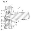
- FIG. 2 is a cross-sectional view of a third embodiment of the water pump disconnect clutch 110.
- the clutch 110 includes a first race 112 having a first diameter 114 and a second diameter 116; a second race 118 having ramps 120 arranged circumferentially; and at least one rolling element 122 disposed radially between the first race 112 and the second race 118.
- the engagement means 124 is arranged to axially displace the rolling element 122 from a first position near the first diameter 114 to a second position (not shown) in contact with the second diameter 116 to engage the coupling 110.
- the diameter 114 is shown smaller than the diameter 116, a configuration in which the diameter 116 is smaller than the diameter 114, that is, when the first race 112 is disposed radially outward of the rolling element 122, is within the scope of the invention.
- a preferred engagement means 124 is a pop-up type thermostat, although other means such as engine vacuum, engine oil or contact friction are within the scope of the invention.
- the engagement means 124 is positioned by the plate 130 and fastener 156 so as to be axially adjacent the second race 118.
- the engagement means 124 axially displaces the second race 118 Characteristics positioned a cage (not shown) a plurality of the first rolling elements 122 in the circumferential direction.
- the shaft 132 may be driven by a motor (not shown).
- a pulley (not shown) driven by a motorized belt (not shown) may be attached to the shaft 132.
- Bearings (not shown) support the shaft 132 in the engine.
- a fastener 134 screwed into the shaft 132 axially retains the engagement means 124 such that axial displacement of the means 124 moves the roller 122 between portions of the race 112.
- the race 112 is incorporated in the shaft 132.
- the fastener 134 is illustrated, other methods such as e.g. Notching, welding, snap lock, rivet connection can be used to hold the means 124 on the shaft 132.
- the clutch 110 also includes a third race 136 connected to a water pump impeller (not shown) and a second rolling element 140 disposed in the channel 142 formed between the second race 118 and the third race 136 ,
- the rolling element 140 advantageously transmits torque from the race 118 to the race 136, yet allows the race 118 to move axially with respect to the low friction race 136.
- the combination of race 118, race 136 and rolling element 140 may be a ball spline assembly.
- the coupling 110 is axially positioned on the shaft 132 via the radial surface 146 and the snap ring 150.
- the axial movement of the rolling element 122 is limited by the flange portion 158 of the second race 118.
- the axial movement of the rolling element 140 is limited by the plate 160, which is attached to the third race 136 by the fastening means 162.
- the operation of the clutch 110 is as described for the clutch 10.
Landscapes
- Engineering & Computer Science (AREA)
- General Engineering & Computer Science (AREA)
- Mechanical Engineering (AREA)
- Structures Of Non-Positive Displacement Pumps (AREA)
- Mechanical Operated Clutches (AREA)
Applications Claiming Priority (1)
| Application Number | Priority Date | Filing Date | Title |
|---|---|---|---|
| US95990307P | 2007-07-17 | 2007-07-17 |
Publications (3)
| Publication Number | Publication Date |
|---|---|
| EP2017490A2 true EP2017490A2 (fr) | 2009-01-21 |
| EP2017490A3 EP2017490A3 (fr) | 2013-07-03 |
| EP2017490B1 EP2017490B1 (fr) | 2014-10-22 |
Family
ID=39870025
Family Applications (1)
| Application Number | Title | Priority Date | Filing Date |
|---|---|---|---|
| EP08160546.1A Not-in-force EP2017490B1 (fr) | 2007-07-17 | 2008-07-16 | Embrayage de coupure de pompe à eau |
Country Status (2)
| Country | Link |
|---|---|
| US (1) | US8056689B2 (fr) |
| EP (1) | EP2017490B1 (fr) |
Cited By (1)
| Publication number | Priority date | Publication date | Assignee | Title |
|---|---|---|---|---|
| WO2012123164A1 (fr) * | 2011-03-14 | 2012-09-20 | Schaeffler Technologies AG & Co. KG | Ensemble roue menante |
Families Citing this family (2)
| Publication number | Priority date | Publication date | Assignee | Title |
|---|---|---|---|---|
| US8745867B1 (en) * | 2013-01-14 | 2014-06-10 | Kit Masters | Modular viscous fan clutch system |
| JP7527202B2 (ja) * | 2020-12-24 | 2024-08-02 | 株式会社クボタ | ファン駆動構造 |
Citations (3)
| Publication number | Priority date | Publication date | Assignee | Title |
|---|---|---|---|---|
| US2570515A (en) | 1948-11-26 | 1951-10-09 | Walter R Bonham | Jamming roller clutch |
| US6619454B2 (en) | 2001-01-24 | 2003-09-16 | Goodrich Control Systems Limited | Thermal disconnect device |
| US6915887B2 (en) | 2001-11-30 | 2005-07-12 | Linning Trucktec Gmbh | Drive member for a water pump of the cooling-water circuit of an internal combustion engine and frictional shift clutch |
Family Cites Families (9)
| Publication number | Priority date | Publication date | Assignee | Title |
|---|---|---|---|---|
| GB131309A (en) * | 1917-04-21 | 1920-11-04 | Wolfgang Magg | Improvements in clutches |
| US3158241A (en) * | 1961-12-26 | 1964-11-24 | Lipe Rollway Corp | Self energizing friction clutch |
| NL294284A (fr) * | 1962-06-20 | |||
| CH427408A (de) * | 1962-06-20 | 1966-12-31 | Seifert Gerd W Ing Dr | Kühlluftgebläseantrieb für Kraftfahrzeuge |
| FR1366025A (fr) * | 1963-05-02 | 1964-07-10 | Dispositif d'accouplement | |
| US3382852A (en) * | 1966-03-30 | 1968-05-14 | Gen Motors Corp | Thermostatically controlled fan |
| US3430519A (en) * | 1967-01-17 | 1969-03-04 | Eaton Yale & Towne | Differential with temperature compensating clutch |
| US4060158A (en) * | 1976-01-28 | 1977-11-29 | Usui International Industry, Ltd. | Cooling fan control mechanism |
| US6684992B2 (en) * | 2001-07-25 | 2004-02-03 | Ntn Corporation | Electronically controllable torque transmission device |
-
2008
- 2008-07-16 EP EP08160546.1A patent/EP2017490B1/fr not_active Not-in-force
- 2008-07-17 US US12/218,645 patent/US8056689B2/en not_active Expired - Fee Related
Patent Citations (3)
| Publication number | Priority date | Publication date | Assignee | Title |
|---|---|---|---|---|
| US2570515A (en) | 1948-11-26 | 1951-10-09 | Walter R Bonham | Jamming roller clutch |
| US6619454B2 (en) | 2001-01-24 | 2003-09-16 | Goodrich Control Systems Limited | Thermal disconnect device |
| US6915887B2 (en) | 2001-11-30 | 2005-07-12 | Linning Trucktec Gmbh | Drive member for a water pump of the cooling-water circuit of an internal combustion engine and frictional shift clutch |
Cited By (1)
| Publication number | Priority date | Publication date | Assignee | Title |
|---|---|---|---|---|
| WO2012123164A1 (fr) * | 2011-03-14 | 2012-09-20 | Schaeffler Technologies AG & Co. KG | Ensemble roue menante |
Also Published As
| Publication number | Publication date |
|---|---|
| US20090055027A1 (en) | 2009-02-26 |
| EP2017490A3 (fr) | 2013-07-03 |
| US8056689B2 (en) | 2011-11-15 |
| EP2017490B1 (fr) | 2014-10-22 |
Similar Documents
| Publication | Publication Date | Title |
|---|---|---|
| DE102015201931A1 (de) | Antriebssystem für ein Hybridfahrzeug | |
| EP3186525B1 (fr) | Embrayage double | |
| DE102009056368A1 (de) | Schaltbare Antriebsscheibe mit einer elektrisch betätigten, eine Reibscheibe aufweisenden Drehmomentübertragungsvorrichtung | |
| DE102009060745A1 (de) | Drehkraftverstärkungsmaschine | |
| DE102009010487A1 (de) | Zweiwegekupplung mit axialer Ausrückung | |
| DE102015226220A1 (de) | Doppelkupplung | |
| EP2875249A1 (fr) | Embrayage double | |
| EP2017490B1 (fr) | Embrayage de coupure de pompe à eau | |
| DE102008061606B4 (de) | Bremsvorrichtung und Motor mit Geschwindigkeitsreduzierungsmechanismus | |
| WO2007124715A1 (fr) | Moyen de fixation utilisant la languette d'une aube de turbine pour un logement de ressort amortisseur d'un convertisseur de couple et procédé de fabrication du moyen de fixation | |
| DE102007058019A1 (de) | Axialer Freilauf mit axialem Abstandselement | |
| DE102017206513A1 (de) | Gelenkwelle | |
| DE102013215448A1 (de) | Segmentierte Anpressplatte für eine Reibkupplung, entsprechende Reibkupplung und entsprechendes Kraftfahrzeug | |
| DE102015225063A1 (de) | Verfahren zum Einstellen des Lüftspiels einer Kupplungseinrichtung | |
| DE102015100906B4 (de) | Synchronisiereinrichtung, Kupplungsanordnung und Antriebsanordnung | |
| DE102005022457A1 (de) | Elektromagnetisch schaltbare Kupplung | |
| EP1870610A2 (fr) | Système de levier et son procédé de montage | |
| WO2008043530A1 (fr) | Dispositif d'accouplement pour une pompe pour réfrigérant, procédé d'accouplement, pompe destinée à des pompes pour réfrigérant | |
| DE102015225319A1 (de) | Ausgleichsvorrichtung zum Ausgleich eines Radialversatzes in einem Drehmomentfluss eines Antriebsstrangs eines Kraftfahrzeugs | |
| DE102022125472A1 (de) | Verbindungseinrichtung zur Verbindung zweier koaxial angeordneter Wellen | |
| DE102014217277A1 (de) | Doppelkupplung | |
| DE102022000740A1 (de) | Freilaufanordnung und Antriebsstrang für ein Kraftfahrzeug mit einer solchen Freilaufanordnung | |
| DE102019106753A1 (de) | Differenzial | |
| DE3013893C2 (fr) | ||
| DE102004017342B4 (de) | Nadellageranordnung und Axialverstellvorrichtung mit Vorhaltung zur optimierten Nadellagerbeanspuchung |
Legal Events
| Date | Code | Title | Description |
|---|---|---|---|
| PUAI | Public reference made under article 153(3) epc to a published international application that has entered the european phase |
Free format text: ORIGINAL CODE: 0009012 |
|
| AK | Designated contracting states |
Kind code of ref document: A2 Designated state(s): AT BE BG CH CY CZ DE DK EE ES FI FR GB GR HR HU IE IS IT LI LT LU LV MC MT NL NO PL PT RO SE SI SK TR |
|
| AX | Request for extension of the european patent |
Extension state: AL BA MK RS |
|
| RAP1 | Party data changed (applicant data changed or rights of an application transferred) |
Owner name: SCHAEFFLER TECHNOLOGIES AG & CO. KG |
|
| PUAL | Search report despatched |
Free format text: ORIGINAL CODE: 0009013 |
|
| AK | Designated contracting states |
Kind code of ref document: A3 Designated state(s): AT BE BG CH CY CZ DE DK EE ES FI FR GB GR HR HU IE IS IT LI LT LU LV MC MT NL NO PL PT RO SE SI SK TR |
|
| AX | Request for extension of the european patent |
Extension state: AL BA MK RS |
|
| RIC1 | Information provided on ipc code assigned before grant |
Ipc: F16D 15/00 20060101AFI20130528BHEP |
|
| 17P | Request for examination filed |
Effective date: 20140103 |
|
| RBV | Designated contracting states (corrected) |
Designated state(s): AT BE BG CH CY CZ DE DK EE ES FI FR GB GR HR HU IE IS IT LI LT LU LV MC MT NL NO PL PT RO SE SI SK TR |
|
| AKX | Designation fees paid |
Designated state(s): AT BE BG CH CY CZ DE DK EE ES FI FR GB GR HR HU IE IS IT LI LT LU LV MC MT NL NO PL PT RO SE SI SK TR |
|
| RAP1 | Party data changed (applicant data changed or rights of an application transferred) |
Owner name: SCHAEFFLER TECHNOLOGIES GMBH & CO. KG |
|
| GRAP | Despatch of communication of intention to grant a patent |
Free format text: ORIGINAL CODE: EPIDOSNIGR1 |
|
| INTG | Intention to grant announced |
Effective date: 20140704 |
|
| GRAS | Grant fee paid |
Free format text: ORIGINAL CODE: EPIDOSNIGR3 |
|
| GRAA | (expected) grant |
Free format text: ORIGINAL CODE: 0009210 |
|
| AK | Designated contracting states |
Kind code of ref document: B1 Designated state(s): AT BE BG CH CY CZ DE DK EE ES FI FR GB GR HR HU IE IS IT LI LT LU LV MC MT NL NO PL PT RO SE SI SK TR |
|
| REG | Reference to a national code |
Ref country code: GB Ref legal event code: FG4D Free format text: NOT ENGLISH |
|
| REG | Reference to a national code |
Ref country code: CH Ref legal event code: EP |
|
| REG | Reference to a national code |
Ref country code: AT Ref legal event code: REF Ref document number: 692806 Country of ref document: AT Kind code of ref document: T Effective date: 20141115 |
|
| REG | Reference to a national code |
Ref country code: IE Ref legal event code: FG4D Free format text: LANGUAGE OF EP DOCUMENT: GERMAN |
|
| REG | Reference to a national code |
Ref country code: DE Ref legal event code: R096 Ref document number: 502008012326 Country of ref document: DE Effective date: 20141204 |
|
| RAP2 | Party data changed (patent owner data changed or rights of a patent transferred) |
Owner name: SCHAEFFLER TECHNOLOGIES AG & CO. KG |
|
| REG | Reference to a national code |
Ref country code: DE Ref legal event code: R081 Ref document number: 502008012326 Country of ref document: DE Owner name: SCHAEFFLER TECHNOLOGIES AG & CO. KG, DE Free format text: FORMER OWNER: SCHAEFFLER TECHNOLOGIES GMBH & CO. KG, 91074 HERZOGENAURACH, DE Effective date: 20150122 |
|
| REG | Reference to a national code |
Ref country code: NL Ref legal event code: VDEP Effective date: 20141022 |
|
| REG | Reference to a national code |
Ref country code: LT Ref legal event code: MG4D |
|
| PG25 | Lapsed in a contracting state [announced via postgrant information from national office to epo] |
Ref country code: IS Free format text: LAPSE BECAUSE OF FAILURE TO SUBMIT A TRANSLATION OF THE DESCRIPTION OR TO PAY THE FEE WITHIN THE PRESCRIBED TIME-LIMIT Effective date: 20150222 Ref country code: PT Free format text: LAPSE BECAUSE OF FAILURE TO SUBMIT A TRANSLATION OF THE DESCRIPTION OR TO PAY THE FEE WITHIN THE PRESCRIBED TIME-LIMIT Effective date: 20150223 Ref country code: ES Free format text: LAPSE BECAUSE OF FAILURE TO SUBMIT A TRANSLATION OF THE DESCRIPTION OR TO PAY THE FEE WITHIN THE PRESCRIBED TIME-LIMIT Effective date: 20141022 Ref country code: FI Free format text: LAPSE BECAUSE OF FAILURE TO SUBMIT A TRANSLATION OF THE DESCRIPTION OR TO PAY THE FEE WITHIN THE PRESCRIBED TIME-LIMIT Effective date: 20141022 Ref country code: NL Free format text: LAPSE BECAUSE OF FAILURE TO SUBMIT A TRANSLATION OF THE DESCRIPTION OR TO PAY THE FEE WITHIN THE PRESCRIBED TIME-LIMIT Effective date: 20141022 Ref country code: NO Free format text: LAPSE BECAUSE OF FAILURE TO SUBMIT A TRANSLATION OF THE DESCRIPTION OR TO PAY THE FEE WITHIN THE PRESCRIBED TIME-LIMIT Effective date: 20150122 Ref country code: LT Free format text: LAPSE BECAUSE OF FAILURE TO SUBMIT A TRANSLATION OF THE DESCRIPTION OR TO PAY THE FEE WITHIN THE PRESCRIBED TIME-LIMIT Effective date: 20141022 |
|
| PG25 | Lapsed in a contracting state [announced via postgrant information from national office to epo] |
Ref country code: CY Free format text: LAPSE BECAUSE OF FAILURE TO SUBMIT A TRANSLATION OF THE DESCRIPTION OR TO PAY THE FEE WITHIN THE PRESCRIBED TIME-LIMIT Effective date: 20141022 Ref country code: HR Free format text: LAPSE BECAUSE OF FAILURE TO SUBMIT A TRANSLATION OF THE DESCRIPTION OR TO PAY THE FEE WITHIN THE PRESCRIBED TIME-LIMIT Effective date: 20141022 Ref country code: SE Free format text: LAPSE BECAUSE OF FAILURE TO SUBMIT A TRANSLATION OF THE DESCRIPTION OR TO PAY THE FEE WITHIN THE PRESCRIBED TIME-LIMIT Effective date: 20141022 Ref country code: GR Free format text: LAPSE BECAUSE OF FAILURE TO SUBMIT A TRANSLATION OF THE DESCRIPTION OR TO PAY THE FEE WITHIN THE PRESCRIBED TIME-LIMIT Effective date: 20150123 Ref country code: PL Free format text: LAPSE BECAUSE OF FAILURE TO SUBMIT A TRANSLATION OF THE DESCRIPTION OR TO PAY THE FEE WITHIN THE PRESCRIBED TIME-LIMIT Effective date: 20141022 Ref country code: LV Free format text: LAPSE BECAUSE OF FAILURE TO SUBMIT A TRANSLATION OF THE DESCRIPTION OR TO PAY THE FEE WITHIN THE PRESCRIBED TIME-LIMIT Effective date: 20141022 |
|
| REG | Reference to a national code |
Ref country code: DE Ref legal event code: R097 Ref document number: 502008012326 Country of ref document: DE |
|
| PG25 | Lapsed in a contracting state [announced via postgrant information from national office to epo] |
Ref country code: EE Free format text: LAPSE BECAUSE OF FAILURE TO SUBMIT A TRANSLATION OF THE DESCRIPTION OR TO PAY THE FEE WITHIN THE PRESCRIBED TIME-LIMIT Effective date: 20141022 Ref country code: RO Free format text: LAPSE BECAUSE OF FAILURE TO SUBMIT A TRANSLATION OF THE DESCRIPTION OR TO PAY THE FEE WITHIN THE PRESCRIBED TIME-LIMIT Effective date: 20141022 Ref country code: CZ Free format text: LAPSE BECAUSE OF FAILURE TO SUBMIT A TRANSLATION OF THE DESCRIPTION OR TO PAY THE FEE WITHIN THE PRESCRIBED TIME-LIMIT Effective date: 20141022 Ref country code: DK Free format text: LAPSE BECAUSE OF FAILURE TO SUBMIT A TRANSLATION OF THE DESCRIPTION OR TO PAY THE FEE WITHIN THE PRESCRIBED TIME-LIMIT Effective date: 20141022 Ref country code: SK Free format text: LAPSE BECAUSE OF FAILURE TO SUBMIT A TRANSLATION OF THE DESCRIPTION OR TO PAY THE FEE WITHIN THE PRESCRIBED TIME-LIMIT Effective date: 20141022 |
|
| PLBE | No opposition filed within time limit |
Free format text: ORIGINAL CODE: 0009261 |
|
| STAA | Information on the status of an ep patent application or granted ep patent |
Free format text: STATUS: NO OPPOSITION FILED WITHIN TIME LIMIT |
|
| PG25 | Lapsed in a contracting state [announced via postgrant information from national office to epo] |
Ref country code: IT Free format text: LAPSE BECAUSE OF FAILURE TO SUBMIT A TRANSLATION OF THE DESCRIPTION OR TO PAY THE FEE WITHIN THE PRESCRIBED TIME-LIMIT Effective date: 20141022 |
|
| 26N | No opposition filed |
Effective date: 20150723 |
|
| REG | Reference to a national code |
Ref country code: DE Ref legal event code: R119 Ref document number: 502008012326 Country of ref document: DE |
|
| PG25 | Lapsed in a contracting state [announced via postgrant information from national office to epo] |
Ref country code: SI Free format text: LAPSE BECAUSE OF FAILURE TO SUBMIT A TRANSLATION OF THE DESCRIPTION OR TO PAY THE FEE WITHIN THE PRESCRIBED TIME-LIMIT Effective date: 20141022 Ref country code: MC Free format text: LAPSE BECAUSE OF FAILURE TO SUBMIT A TRANSLATION OF THE DESCRIPTION OR TO PAY THE FEE WITHIN THE PRESCRIBED TIME-LIMIT Effective date: 20141022 |
|
| REG | Reference to a national code |
Ref country code: CH Ref legal event code: PL |
|
| GBPC | Gb: european patent ceased through non-payment of renewal fee |
Effective date: 20150716 |
|
| PG25 | Lapsed in a contracting state [announced via postgrant information from national office to epo] |
Ref country code: LU Free format text: LAPSE BECAUSE OF FAILURE TO SUBMIT A TRANSLATION OF THE DESCRIPTION OR TO PAY THE FEE WITHIN THE PRESCRIBED TIME-LIMIT Effective date: 20150716 |
|
| REG | Reference to a national code |
Ref country code: IE Ref legal event code: MM4A |
|
| PG25 | Lapsed in a contracting state [announced via postgrant information from national office to epo] |
Ref country code: GB Free format text: LAPSE BECAUSE OF NON-PAYMENT OF DUE FEES Effective date: 20150716 Ref country code: CH Free format text: LAPSE BECAUSE OF NON-PAYMENT OF DUE FEES Effective date: 20150731 Ref country code: DE Free format text: LAPSE BECAUSE OF NON-PAYMENT OF DUE FEES Effective date: 20160202 Ref country code: LI Free format text: LAPSE BECAUSE OF NON-PAYMENT OF DUE FEES Effective date: 20150731 |
|
| REG | Reference to a national code |
Ref country code: FR Ref legal event code: ST Effective date: 20160331 |
|
| PG25 | Lapsed in a contracting state [announced via postgrant information from national office to epo] |
Ref country code: FR Free format text: LAPSE BECAUSE OF NON-PAYMENT OF DUE FEES Effective date: 20150731 |
|
| PG25 | Lapsed in a contracting state [announced via postgrant information from national office to epo] |
Ref country code: IE Free format text: LAPSE BECAUSE OF NON-PAYMENT OF DUE FEES Effective date: 20150716 |
|
| REG | Reference to a national code |
Ref country code: AT Ref legal event code: MM01 Ref document number: 692806 Country of ref document: AT Kind code of ref document: T Effective date: 20150716 |
|
| PG25 | Lapsed in a contracting state [announced via postgrant information from national office to epo] |
Ref country code: AT Free format text: LAPSE BECAUSE OF NON-PAYMENT OF DUE FEES Effective date: 20150716 |
|
| PG25 | Lapsed in a contracting state [announced via postgrant information from national office to epo] |
Ref country code: MT Free format text: LAPSE BECAUSE OF FAILURE TO SUBMIT A TRANSLATION OF THE DESCRIPTION OR TO PAY THE FEE WITHIN THE PRESCRIBED TIME-LIMIT Effective date: 20141022 |
|
| PG25 | Lapsed in a contracting state [announced via postgrant information from national office to epo] |
Ref country code: HU Free format text: LAPSE BECAUSE OF FAILURE TO SUBMIT A TRANSLATION OF THE DESCRIPTION OR TO PAY THE FEE WITHIN THE PRESCRIBED TIME-LIMIT; INVALID AB INITIO Effective date: 20080716 Ref country code: BG Free format text: LAPSE BECAUSE OF FAILURE TO SUBMIT A TRANSLATION OF THE DESCRIPTION OR TO PAY THE FEE WITHIN THE PRESCRIBED TIME-LIMIT Effective date: 20141022 |
|
| PG25 | Lapsed in a contracting state [announced via postgrant information from national office to epo] |
Ref country code: BE Free format text: LAPSE BECAUSE OF NON-PAYMENT OF DUE FEES Effective date: 20150731 |
|
| PG25 | Lapsed in a contracting state [announced via postgrant information from national office to epo] |
Ref country code: TR Free format text: LAPSE BECAUSE OF FAILURE TO SUBMIT A TRANSLATION OF THE DESCRIPTION OR TO PAY THE FEE WITHIN THE PRESCRIBED TIME-LIMIT Effective date: 20141022 |
|
| P01 | Opt-out of the competence of the unified patent court (upc) registered |
Effective date: 20230522 |