EP2017530A2 - Air independent chimney system for dwellings - Google Patents
Air independent chimney system for dwellings Download PDFInfo
- Publication number
- EP2017530A2 EP2017530A2 EP08159479A EP08159479A EP2017530A2 EP 2017530 A2 EP2017530 A2 EP 2017530A2 EP 08159479 A EP08159479 A EP 08159479A EP 08159479 A EP08159479 A EP 08159479A EP 2017530 A2 EP2017530 A2 EP 2017530A2
- Authority
- EP
- European Patent Office
- Prior art keywords
- combustion air
- fireplace
- flue gas
- chimney
- stove
- Prior art date
- Legal status (The legal status is an assumption and is not a legal conclusion. Google has not performed a legal analysis and makes no representation as to the accuracy of the status listed.)
- Withdrawn
Links
- 238000002485 combustion reaction Methods 0.000 claims abstract description 28
- 239000003546 flue gas Substances 0.000 claims abstract description 20
- UGFAIRIUMAVXCW-UHFFFAOYSA-N Carbon monoxide Chemical compound [O+]#[C-] UGFAIRIUMAVXCW-UHFFFAOYSA-N 0.000 claims abstract description 19
- 238000009413 insulation Methods 0.000 claims abstract description 5
- 239000000919 ceramic Substances 0.000 claims abstract description 3
- 239000002557 mineral fiber Substances 0.000 claims abstract description 3
- 238000005338 heat storage Methods 0.000 claims description 9
- 239000004575 stone Substances 0.000 claims description 2
- 239000007789 gas Substances 0.000 abstract 1
- 239000000779 smoke Substances 0.000 abstract 1
- XLYOFNOQVPJJNP-UHFFFAOYSA-N water Substances O XLYOFNOQVPJJNP-UHFFFAOYSA-N 0.000 description 4
- 239000011521 glass Substances 0.000 description 3
- 239000011449 brick Substances 0.000 description 2
- 230000001681 protective effect Effects 0.000 description 2
- 238000010276 construction Methods 0.000 description 1
- 238000011109 contamination Methods 0.000 description 1
- 239000013505 freshwater Substances 0.000 description 1
- 210000004907 gland Anatomy 0.000 description 1
- 238000010438 heat treatment Methods 0.000 description 1
- 239000002245 particle Substances 0.000 description 1
- 230000005855 radiation Effects 0.000 description 1
Images

Classifications
-
- F—MECHANICAL ENGINEERING; LIGHTING; HEATING; WEAPONS; BLASTING
- F23—COMBUSTION APPARATUS; COMBUSTION PROCESSES
- F23J—REMOVAL OR TREATMENT OF COMBUSTION PRODUCTS OR COMBUSTION RESIDUES; FLUES
- F23J11/00—Devices for conducting smoke or fumes, e.g. flues
-
- F—MECHANICAL ENGINEERING; LIGHTING; HEATING; WEAPONS; BLASTING
- F23—COMBUSTION APPARATUS; COMBUSTION PROCESSES
- F23J—REMOVAL OR TREATMENT OF COMBUSTION PRODUCTS OR COMBUSTION RESIDUES; FLUES
- F23J13/00—Fittings for chimneys or flues
- F23J13/02—Linings; Jackets; Casings
- F23J13/025—Linings; Jackets; Casings composed of concentric elements, e.g. double walled
-
- F—MECHANICAL ENGINEERING; LIGHTING; HEATING; WEAPONS; BLASTING
- F24—HEATING; RANGES; VENTILATING
- F24B—DOMESTIC STOVES OR RANGES FOR SOLID FUELS; IMPLEMENTS FOR USE IN CONNECTION WITH STOVES OR RANGES
- F24B1/00—Stoves or ranges
- F24B1/18—Stoves with open fires, e.g. fireplaces
-
- F—MECHANICAL ENGINEERING; LIGHTING; HEATING; WEAPONS; BLASTING
- F24—HEATING; RANGES; VENTILATING
- F24B—DOMESTIC STOVES OR RANGES FOR SOLID FUELS; IMPLEMENTS FOR USE IN CONNECTION WITH STOVES OR RANGES
- F24B1/00—Stoves or ranges
- F24B1/18—Stoves with open fires, e.g. fireplaces
- F24B1/185—Stoves with open fires, e.g. fireplaces with air-handling means, heat exchange means, or additional provisions for convection heating ; Controlling combustion
- F24B1/189—Stoves with open fires, e.g. fireplaces with air-handling means, heat exchange means, or additional provisions for convection heating ; Controlling combustion characterised by air-handling means, i.e. of combustion-air, heated-air, or flue-gases, e.g. draught control dampers
-
- F—MECHANICAL ENGINEERING; LIGHTING; HEATING; WEAPONS; BLASTING
- F23—COMBUSTION APPARATUS; COMBUSTION PROCESSES
- F23J—REMOVAL OR TREATMENT OF COMBUSTION PRODUCTS OR COMBUSTION RESIDUES; FLUES
- F23J2211/00—Flue gas duct systems
- F23J2211/10—Balanced flues (combining air supply and flue gas exhaust)
- F23J2211/101—Balanced flues (combining air supply and flue gas exhaust) with coaxial duct arrangement
-
- F—MECHANICAL ENGINEERING; LIGHTING; HEATING; WEAPONS; BLASTING
- F24—HEATING; RANGES; VENTILATING
- F24D—DOMESTIC- OR SPACE-HEATING SYSTEMS, e.g. CENTRAL HEATING SYSTEMS; DOMESTIC HOT-WATER SUPPLY SYSTEMS; ELEMENTS OR COMPONENTS THEREFOR
- F24D2200/00—Heat sources or energy sources
- F24D2200/10—Fire place
-
- F—MECHANICAL ENGINEERING; LIGHTING; HEATING; WEAPONS; BLASTING
- F24—HEATING; RANGES; VENTILATING
- F24D—DOMESTIC- OR SPACE-HEATING SYSTEMS, e.g. CENTRAL HEATING SYSTEMS; DOMESTIC HOT-WATER SUPPLY SYSTEMS; ELEMENTS OR COMPONENTS THEREFOR
- F24D2200/00—Heat sources or energy sources
- F24D2200/14—Solar energy
-
- Y—GENERAL TAGGING OF NEW TECHNOLOGICAL DEVELOPMENTS; GENERAL TAGGING OF CROSS-SECTIONAL TECHNOLOGIES SPANNING OVER SEVERAL SECTIONS OF THE IPC; TECHNICAL SUBJECTS COVERED BY FORMER USPC CROSS-REFERENCE ART COLLECTIONS [XRACs] AND DIGESTS
- Y02—TECHNOLOGIES OR APPLICATIONS FOR MITIGATION OR ADAPTATION AGAINST CLIMATE CHANGE
- Y02B—CLIMATE CHANGE MITIGATION TECHNOLOGIES RELATED TO BUILDINGS, e.g. HOUSING, HOUSE APPLIANCES OR RELATED END-USER APPLICATIONS
- Y02B10/00—Integration of renewable energy sources in buildings
- Y02B10/20—Solar thermal
-
- Y—GENERAL TAGGING OF NEW TECHNOLOGICAL DEVELOPMENTS; GENERAL TAGGING OF CROSS-SECTIONAL TECHNOLOGIES SPANNING OVER SEVERAL SECTIONS OF THE IPC; TECHNICAL SUBJECTS COVERED BY FORMER USPC CROSS-REFERENCE ART COLLECTIONS [XRACs] AND DIGESTS
- Y02—TECHNOLOGIES OR APPLICATIONS FOR MITIGATION OR ADAPTATION AGAINST CLIMATE CHANGE
- Y02B—CLIMATE CHANGE MITIGATION TECHNOLOGIES RELATED TO BUILDINGS, e.g. HOUSING, HOUSE APPLIANCES OR RELATED END-USER APPLICATIONS
- Y02B10/00—Integration of renewable energy sources in buildings
- Y02B10/70—Hybrid systems, e.g. uninterruptible or back-up power supplies integrating renewable energies
Definitions
- the invention relates to a fireplace system for a residential building.
- a stove in the living area.
- Such a stove is often the expression of a special living culture for the residents and also serves as a jewelry and representation of the living space.
- the stove is usually arranged in a wall recess or a niche and preferably has an open hearth, the heat is given mainly by radiation from the open fire to the room.
- the energy yield is low because most of the heat is dissipated with the flue gases through the chimney.
- a problem is also often seen in the fact that sparks and ash particles in an open hearth can get into the living room.
- a fireplace system for a residential building having a chimney comprising a tubular flue gas duct for the discharge of flue gas and a combustion air duct for combustion air supply, wherein in a lower portion of the chimney, a stove is arranged, which receives combustion air from the combustion air duct and the the flue gas produced during combustion releases via the flue gas channel.
- the combustion air supply for the fireplace is not carried out by the living room in which the fireplace is located, but via a special combustion air duct, which is preferably integrated as an annular gap in the fireplace. Accordingly, the fireplace is independent of the room air and does not consume them.
- the fireplace system is designed so that the fireplace only receives combustion air from the combustion air duct. Accordingly, the fireplace in the stove opposite the living space can be completely completed, for example, by providing a protective glass on the door of the fireplace. This protective glass can be largely sealed airtight with the chimney opening. In such an arrangement, the inhabitants of the residential building can continue to comfortably absorb the radiant heat of the fire and enjoy the play of the flames. Due to the seclusion of the fireplace, the risk of contamination is reduced. Furthermore, the energy yield is improved due to the seclusion under combustion air supply from the outside.
- a heat exchanger with a heating medium e.g. Water, arranged, wherein the heat medium is heated by the fire of the fireplace and the heat absorbed to a remote heat storage, preferably a solar heat storage, is supplied.
- a heating medium e.g. Water
- a remote heat storage preferably a solar heat storage
- a further improvement of the energy yield is achieved by arranging a solar system on the roof of the residential building, which supplies heat to the solar thermal storage.
- the heated by solar energy medium of the solar heat storage, such as water, is further increased by the fire of the fireplace so that a high energy efficiency is ensured within the residential building.
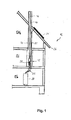
- FIG. 1 schematically a section of a residential building 10 is shown, which comprises a loft DG, a ground floor EC and a basement KG.
- a stove 12 with a chimney 14 is arranged in the ground floor EC .
- the chimney 14 comprises an internal flue gas duct 16 and a combustion air duct 18 arranged concentrically around the flue gas duct 16.
- Connections 23 go from a fireplace 30 to a solar heat accumulator 20, which is arranged in the basement KG.
- Lines 22 lead to a solar system 24, which is installed on the roof 26 of the residential building 10 and solar energy converts into heat energy.
- the lines 23 lead directly from the fireplace 30 in the stove 12 in the solar heat storage 20th
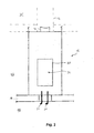
- FIG. 2 shows the construction of the stove 12, which is located room-high in the ground floor EC above a basement ceiling 28, which separates the ground floor EC from basement KG.
- the stove 12 includes the fireplace 30, which is closed by a door 32, for example made of heat-resistant glass, and is used to load and clean the fireplace 30.
- a flow line 34 and a return line 36 lead through the basement ceiling 28 through to the solar heat storage 20, which is arranged in the basement KG.
- the flow line 34 and return line 36 lead to a heat exchanger surrounding the fireplace 30, wherein the heat medium flowing in it, eg water, is heated by the fire.
- a connection for the chimney 14 is provided at the upper end of the fireplace stove 12.
- FIG. 3 shows an embodiment of the fireplace 30 from behind with their connections.
- the stove 12 may typically have a power of 6 to 15 kW, wherein the amount attributable to the solar heat storage capacity is about 70%.
- the fireplace 30 includes a pipe opening 38 for the combustion air supply, as well as connections 40, 42 for the supply line 34 and the return line 36. In the lower part of two cable glands 44 are provided, can be passed through the electrical cables for the electrical control and the thermal fuse. In the upper part of the picture there is a connection 46 for the flue gas duct 16. Connections 46, 48 serve for the fresh water inlet and a water outlet.
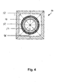
- FIG. 4 shows a cross section through the chimney 14.
- This chimney 14 is composed of storey-high components.
- the chimney 14 is constructed in a space-saving, concentric design. It comprises an outer shell brick 50 made of lightweight concrete. Inside, an insulation 52 of mineral fiber is arranged in a ring. Between the insulation 52 and the casing stone 50 of the combustion air duct 18 extends into the casing brick 50 ports can be admitted at any point to remove combustion air from the combustion air duct 18.
- a column 54 is arranged from socket pipes of high-quality fine ceramics. The column 54 typically has a diameter of 10 to 20 cm.
- the flue gas duct 16 is conveyed through the flue gas from the fireplace to the outside of the residential building 10.
Landscapes
- Engineering & Computer Science (AREA)
- Chemical & Material Sciences (AREA)
- Combustion & Propulsion (AREA)
- Mechanical Engineering (AREA)
- General Engineering & Computer Science (AREA)
- Solid-Fuel Combustion (AREA)
- Building Environments (AREA)
Abstract
Description
Die Erfindung betrifft ein Kaminsystem für ein Wohngebäude. In Wohngebäuden besteht häufig der Wunsch, einen Kaminofen in den Wohnbereich einzubeziehen. Ein solcher Kaminofen ist häufig für die Bewohner Ausdruck einer besonderen Wohnkultur und dient außerdem als Schmuck und Repräsentation für den Wohnraum. Der Kaminofen ist normalerweise in einer Mauernische oder einer Wandnische angeordnet und hat vorzugsweise eine offene Feuerstelle, deren Wärme überwiegend durch Strahlung des offenen Feuers an den Raum abgegeben wird. Die Energieausbeute ist jedoch gering, da der größte Teil der Wärme mit den Rauchgasen durch den Schornstein abgeführt wird. Ein Problem wird auch häufig darin gesehen, dass Funken und Ascheteilchen bei einer offenen Feuerstelle in den Wohnraum gelangen können.The invention relates to a fireplace system for a residential building. In residential buildings, there is often the desire to include a stove in the living area. Such a stove is often the expression of a special living culture for the residents and also serves as a jewelry and representation of the living space. The stove is usually arranged in a wall recess or a niche and preferably has an open hearth, the heat is given mainly by radiation from the open fire to the room. However, the energy yield is low because most of the heat is dissipated with the flue gases through the chimney. A problem is also often seen in the fact that sparks and ash particles in an open hearth can get into the living room.
Es ist Aufgabe der Erfindung, ein Kaminsystem anzugeben, das eine hohe Energieausbeute bei einer geringen Verschmutzung hat.It is an object of the invention to provide a fireplace system that has a high energy yield with low pollution.
Diese Aufgabe wird durch ein Kaminsystem für ein Wohngebäude gelöst, das einen Schornstein aufweist, umfassend einen rohrförmigen Rauchgaskanal zur Ableitung von Rauchgas und einen Verbrennungsluftkanal zur Verbrennungsluftzuführung, wobei in einem unteren Abschnitt des Schornsteins ein Kaminofen angeordnet ist, der Verbrennungsluft aus dem Verbrennungsluftkanal erhält und der das bei Verbrennung entstehende Rauchgas über den Rauchgaskanal abgibt.This object is achieved by a fireplace system for a residential building having a chimney comprising a tubular flue gas duct for the discharge of flue gas and a combustion air duct for combustion air supply, wherein in a lower portion of the chimney, a stove is arranged, which receives combustion air from the combustion air duct and the the flue gas produced during combustion releases via the flue gas channel.
Gemäß der Erfindung erfolgt die Verbrennungsluftzufuhr für die Feuerstätte nicht durch den Wohnraum, in welchem die Feuerstätte angeordnet ist, sondern über einen speziellen Verbrennungsluftkanal, welcher vorzugsweise als Ringspalt im Kamin integriert ist. Demgemäß ist die Feuerstätte unabhängig von der Raumluft und verbraucht diese nicht. Das Kaminsystem ist so ausgelegt, dass die Feuerstätte ausschließlich Verbrennungsluft aus dem Verbrennungsluftkanal erhält. Demgemäß kann die Feuerstätte im Kaminofen gegenüber dem Wohnraum vollständig abgeschlossen werden, beispielsweise durch Vorsehen eines Schutzglases an der Tür der Feuerstätte. Dieses Schutzglas kann weitgehend luftdicht mit der Kaminöffnung abgeschlossen sein. Die Bewohner des Wohngebäudes können bei einer solchen Anordnung weiterhin die Strahlungswärme des Feuers behaglich aufnehmen und sich am Spiel der Flammen erfreuen. Aufgrund der Abgeschlossenheit der Feuerstätte ist die Verschmutzungsgefahr verringert. Weiterhin ist infolge der Abgeschlossenheit unter Verbrennungsluftzufuhr von außen die Energieausbeute verbessert.According to the invention, the combustion air supply for the fireplace is not carried out by the living room in which the fireplace is located, but via a special combustion air duct, which is preferably integrated as an annular gap in the fireplace. Accordingly, the fireplace is independent of the room air and does not consume them. The fireplace system is designed so that the fireplace only receives combustion air from the combustion air duct. Accordingly, the fireplace in the stove opposite the living space can be completely completed, for example, by providing a protective glass on the door of the fireplace. This protective glass can be largely sealed airtight with the chimney opening. In such an arrangement, the inhabitants of the residential building can continue to comfortably absorb the radiant heat of the fire and enjoy the play of the flames. Due to the seclusion of the fireplace, the risk of contamination is reduced. Furthermore, the energy yield is improved due to the seclusion under combustion air supply from the outside.
Gemäß einem bevorzugten Ausführungsbeispiel ist im Bereich der Feuerstätte ein Wärmetauscher mit einem Wärmemedium, z.B. Wasser, angeordnet, wobei das Wärmemedium vom Feuer der Feuerstätte erwärmt wird und die aufgenommene Wärme einem entfernt angeordneten Wärmespeicher, vorzugsweise einem Solarwärmespeicher, zugeführt wird. Auf diese Weise wird die Wärmeenergie der Feuerstätte mit einem erhöhten Wirkungsgrad ausgenützt.According to a preferred embodiment, in the area of the fireplace a heat exchanger with a heating medium, e.g. Water, arranged, wherein the heat medium is heated by the fire of the fireplace and the heat absorbed to a remote heat storage, preferably a solar heat storage, is supplied. In this way, the heat energy of the fireplace is exploited with an increased efficiency.
Eine weitere Verbesserung der Energieausbeute wird dadurch erreicht, dass eine Solaranlage auf dem Dach des Wohngebäudes angeordnet ist, die dem Solarwärmespeicher Wärme zuführt. Das durch Sonnenenergie erwärmte Medium des Solarwärmespeichers, beispielsweise Wasser, wird durch das Feuer der Feuerstätte weiter erhöht, so dass innerhalb des Wohngebäudes eine hohe Energieausnutzung gewährleistet ist.A further improvement of the energy yield is achieved by arranging a solar system on the roof of the residential building, which supplies heat to the solar thermal storage. The heated by solar energy medium of the solar heat storage, such as water, is further increased by the fire of the fireplace so that a high energy efficiency is ensured within the residential building.
Ausführungsbeispiele der Erfindung werden nachfolgend anhand der Zeichnung erläutert. Darin zeigt
- Figur 1
- schematisch ein Kaminofenystem für ein Wohngebäude, wobei eine Feuerstätte im Erdgeschoss angeordnet ist,
- Figur 2
- eine schematische Ansicht des Kaminofens mit Feuerstätte,
- Figur 3
- verschiedene Anschlüsse für den Kaminofen, und
- Figur 4
- einen Querschnitt durch einen Schornsteinabschnitt mit Verbrennungsluftkanal und Rauchgaskanal.
- FIG. 1
- schematically a stove system for a residential building, wherein a fireplace is arranged on the ground floor,
- FIG. 2
- a schematic view of the stove with fireplace,
- FIG. 3
- different connections for the stove, and
- FIG. 4
- a cross section through a chimney section with combustion air duct and flue gas duct.
In
Claims (7)
mit einem Kaminofen (12), darauf aufbauend ein Schornstein (14) mit einem rohrförmigen Rauchgaskanal (16) zur Ableitung von Rauchgas und einem Verbrennungsluftkanal (18) zur Verbrennungsluftzuführung,
wobei der Kaminofen (12) eine Feuerstätte (30) enthält, die Verbrennungsluft aus dem Verbrennungsluftkanal (18) erhält und die das bei Verbrennung entstehende Rauchgas über den Rauchgaskanal (16) abgibt.Fireplace system for a residential building (10),
with a stove (12), building thereon a chimney (14) with a tubular flue gas duct (16) for the discharge of flue gas and a combustion air duct (18) for combustion air supply,
wherein the stove (12) includes a fireplace (30) which receives combustion air from the combustion air duct (18) and which discharges the flue gas resulting from combustion via the flue gas duct (16).
Applications Claiming Priority (1)
| Application Number | Priority Date | Filing Date | Title |
|---|---|---|---|
| DE200720009821 DE202007009821U1 (en) | 2007-07-13 | 2007-07-13 | Room air independent chimney system for residential buildings |
Publications (2)
| Publication Number | Publication Date |
|---|---|
| EP2017530A2 true EP2017530A2 (en) | 2009-01-21 |
| EP2017530A3 EP2017530A3 (en) | 2010-06-02 |
Family
ID=39864756
Family Applications (1)
| Application Number | Title | Priority Date | Filing Date |
|---|---|---|---|
| EP08159479A Withdrawn EP2017530A3 (en) | 2007-07-13 | 2008-07-02 | Air independent chimney system for dwellings |
Country Status (2)
| Country | Link |
|---|---|
| EP (1) | EP2017530A3 (en) |
| DE (1) | DE202007009821U1 (en) |
Cited By (1)
| Publication number | Priority date | Publication date | Assignee | Title |
|---|---|---|---|---|
| CN111503709A (en) * | 2020-04-29 | 2020-08-07 | 重庆大学 | A solar hot water heating system assisted by a biomass fuel boiler and a control method |
Families Citing this family (1)
| Publication number | Priority date | Publication date | Assignee | Title |
|---|---|---|---|---|
| EP2792961B1 (en) | 2013-04-19 | 2019-07-31 | Peter Häusler | Heat exchange unit |
Citations (1)
| Publication number | Priority date | Publication date | Assignee | Title |
|---|---|---|---|---|
| DE19538536A1 (en) * | 1995-10-17 | 1997-04-24 | Dennert Kg Veit | Prefabricated condensation flue for heating system with low flue gas temperature |
Family Cites Families (15)
| Publication number | Priority date | Publication date | Assignee | Title |
|---|---|---|---|---|
| DK108194C (en) * | 1960-07-06 | 1967-10-09 | Sten Wilhelm Larsvall | Heating systems for residential buildings and similar buildings. |
| DE2731835A1 (en) * | 1977-07-14 | 1979-02-01 | Duerkop Hermann | Composite chimney stack section with insulation - encloses insulation with pipes carrying water heated by flue gases |
| US4334518A (en) * | 1980-05-28 | 1982-06-15 | Sol-Fire Inc. | Heating system |
| DE3020182A1 (en) * | 1980-05-28 | 1981-12-03 | Walter Dr.-Ing. 5100 Aachen Jürgens | Air supply arrangement for open or enclosed domestic fireplaces - uses duct from outside building direct to fireplace, possibly with blower |
| DE3024144A1 (en) * | 1980-06-27 | 1982-01-14 | Helmut 7500 Karlsruhe Latzko | Smoke heat recovery system - is for domestic chimney and uses water-filled sheath round flue |
| AT375164B (en) * | 1981-05-15 | 1984-07-10 | Strohl Edwin Ing | FIREPLACE ELEMENT |
| US4414957A (en) * | 1982-03-17 | 1983-11-15 | Ting Enterprises, Inc. | Fireplace and stove apparatus |
| DE4231621A1 (en) * | 1992-09-22 | 1993-06-09 | Anton A. 6653 Blieskastel De Caruso | Integrated heating and heat recovery from combustion gases - has sealed space surrounding primary exhaust gas flue, boiler, heated water store etc. and is adaptable for all fuel types |
| DE4305998A1 (en) * | 1993-02-26 | 1994-09-01 | Selkirk Schornsteintechnik Gmb | Supply-air and waste-gas guide apparatus for fuel-heated heat sources |
| DE29814772U1 (en) * | 1998-08-18 | 2000-01-05 | Münz, Werner, Dipl.-Ing., 85375 Neufahrn | Heat exchanger chimney with exhaust air use |
| DE19852640A1 (en) * | 1998-11-14 | 1999-11-11 | Btg Bautechnik Gmbh & Co | Chimney for a domestic heating system |
| US6550687B2 (en) * | 2000-04-10 | 2003-04-22 | Hon Technology Inc. | Heat exchange system |
| CZ20031182A3 (en) * | 2003-04-28 | 2004-12-15 | Radovan Vojtasík | Fireplace or fire-stove and method for utilizing primary heat |
| DE102004010214B3 (en) * | 2004-03-02 | 2005-06-23 | Schiedel Gmbh & Co. | Modular chimney system has partition walls between air feed channels and central flue of each chimney block provided with longitudinal channels receiving ribs on outside of flue liner |
| DE202007010849U1 (en) * | 2007-08-03 | 2007-12-13 | Vogel, Frank, Dipl.-Ing. (FH) | Heating system |
-
2007
- 2007-07-13 DE DE200720009821 patent/DE202007009821U1/en not_active Expired - Lifetime
-
2008
- 2008-07-02 EP EP08159479A patent/EP2017530A3/en not_active Withdrawn
Patent Citations (1)
| Publication number | Priority date | Publication date | Assignee | Title |
|---|---|---|---|---|
| DE19538536A1 (en) * | 1995-10-17 | 1997-04-24 | Dennert Kg Veit | Prefabricated condensation flue for heating system with low flue gas temperature |
Cited By (1)
| Publication number | Priority date | Publication date | Assignee | Title |
|---|---|---|---|---|
| CN111503709A (en) * | 2020-04-29 | 2020-08-07 | 重庆大学 | A solar hot water heating system assisted by a biomass fuel boiler and a control method |
Also Published As
| Publication number | Publication date |
|---|---|
| DE202007009821U1 (en) | 2009-03-12 |
| EP2017530A3 (en) | 2010-06-02 |
Similar Documents
| Publication | Publication Date | Title |
|---|---|---|
| EP2385302B1 (en) | Chimney system | |
| EP1437550A1 (en) | Device operating a fire for domestic use | |
| EP2017530A2 (en) | Air independent chimney system for dwellings | |
| CH678443A5 (en) | Double flue chimney - comprises pipes and casing of ductile material without concrete brickwork or ceramic material | |
| EP4030101B1 (en) | Chimney with fireplace | |
| WO2010019978A2 (en) | Heating module for integration in the structure of a house | |
| DE10125177A1 (en) | Exhaust gas assembly for a heating system, using a liquid or gas fuel, has an inner exhaust pipe within an outer mantle to give ventilation, surrounded by a cuff with foaming material at a wall/ceiling passage to seal it off in a fire | |
| EP2851486A1 (en) | Concentric chimney construction with inlet and exhaust air duct | |
| EP1532397B1 (en) | Device for guiding and evacuating used air | |
| WO2010063046A1 (en) | Method and apparatus for cascaded biomass oxidation with thermal feedback | |
| EP3620717A1 (en) | Furnace module for building | |
| AT387445B (en) | Heating system | |
| CN104214768B (en) | Biomass combustor | |
| DE102004011017B4 (en) | Ground or tile oven for burning solid fuel, especially wood pellets, has a thermostatically controlled pellet burner that is held within a furnace chamber | |
| DE102008007819B4 (en) | Installable heat storage furnace | |
| DE19925488A1 (en) | Chimney construction with combustion air supply | |
| CH668824A5 (en) | CHIMNEY PIECE. | |
| AT11488U1 (en) | TWO-OLD CHIMNEY SYSTEM | |
| DE2819551A1 (en) | HEATING SYSTEM | |
| DE839241C (en) | Pre-firing with cooling protection for pull-out locomobile boilers | |
| DE29609804U1 (en) | Flue gas flue for stove and oven with this flue gas flue | |
| DE3716000A1 (en) | Heating unit | |
| DE962389C (en) | Air heater for hot air turbines with closed circuit | |
| AT224301B (en) | Heating system with a dome-like tile jacket that is closed on all sides and heated with hot air as a radiator | |
| DE3115811A1 (en) | Furnace arrangement for hot-water preparation and heating |
Legal Events
| Date | Code | Title | Description |
|---|---|---|---|
| PUAI | Public reference made under article 153(3) epc to a published international application that has entered the european phase |
Free format text: ORIGINAL CODE: 0009012 |
|
| AK | Designated contracting states |
Kind code of ref document: A2 Designated state(s): AT BE BG CH CY CZ DE DK EE ES FI FR GB GR HR HU IE IS IT LI LT LU LV MC MT NL NO PL PT RO SE SI SK TR |
|
| AX | Request for extension of the european patent |
Extension state: AL BA MK RS |
|
| PUAL | Search report despatched |
Free format text: ORIGINAL CODE: 0009013 |
|
| AK | Designated contracting states |
Kind code of ref document: A3 Designated state(s): AT BE BG CH CY CZ DE DK EE ES FI FR GB GR HR HU IE IS IT LI LT LU LV MC MT NL NO PL PT RO SE SI SK TR |
|
| AX | Request for extension of the european patent |
Extension state: AL BA MK RS |
|
| RIC1 | Information provided on ipc code assigned before grant |
Ipc: F24D 11/02 20060101ALI20100428BHEP Ipc: F24B 1/187 20060101ALI20100428BHEP Ipc: F23J 13/02 20060101ALI20100428BHEP Ipc: F23J 11/00 20060101AFI20081028BHEP |
|
| 17P | Request for examination filed |
Effective date: 20101111 |
|
| AKX | Designation fees paid |
Designated state(s): AT BE BG CH CY CZ DE DK EE ES FI FR GB GR HR HU IE IS IT LI LT LU LV MC MT NL NO PL PT RO SE SI SK TR |
|
| 17Q | First examination report despatched |
Effective date: 20140801 |
|
| STAA | Information on the status of an ep patent application or granted ep patent |
Free format text: STATUS: THE APPLICATION HAS BEEN WITHDRAWN |
|
| 18W | Application withdrawn |
Effective date: 20141222 |