EP2017533B1 - Float-Wandanordnungen und damit verbundene Systeme - Google Patents
Float-Wandanordnungen und damit verbundene Systeme Download PDFInfo
- Publication number
- EP2017533B1 EP2017533B1 EP08252362.2A EP08252362A EP2017533B1 EP 2017533 B1 EP2017533 B1 EP 2017533B1 EP 08252362 A EP08252362 A EP 08252362A EP 2017533 B1 EP2017533 B1 EP 2017533B1
- Authority
- EP
- European Patent Office
- Prior art keywords
- panel
- region
- combustion section
- porosity
- mount
- Prior art date
- Legal status (The legal status is an assumption and is not a legal conclusion. Google has not performed a legal analysis and makes no representation as to the accuracy of the status listed.)
- Not-in-force
Links
Images

Classifications
-
- F—MECHANICAL ENGINEERING; LIGHTING; HEATING; WEAPONS; BLASTING
- F23—COMBUSTION APPARATUS; COMBUSTION PROCESSES
- F23R—GENERATING COMBUSTION PRODUCTS OF HIGH PRESSURE OR HIGH VELOCITY, e.g. GAS-TURBINE COMBUSTION CHAMBERS
- F23R3/00—Continuous combustion chambers using liquid or gaseous fuel
- F23R3/007—Continuous combustion chambers using liquid or gaseous fuel constructed mainly of ceramic components
Definitions
- This invention generally relates to floatwall panels for combustion sections of gas turbine engines.
- Cooling of materials that are used to form combustion sections of gas turbine engines is accomplished using various techniques.
- some materials that are used to line combustion sections incorporate film-cooling holes that are drilled through the materials at relatively shallow angles. Cooling air is provided to a backside of these materials, thereby allowing the air to travel through the film-cooling holes and cool a surface of the material that Is closest to the combusting fuel and air mixture.
- a technique tends to be relatively inefficient in the use of cooling air.
- the use of such a technique can still result in "hot spots" that can produce cracks in the material and material loss due to oxidation.
- EP-A-1748253 discloses a floatwall panel for a combustion section of a gas turbine comprising a porous material.
- an exemplary embodiment of a floatwall panel assembly comprises: a panel formed of porous ceramic material, the porous ceramic material exhibiting a porosity gradient along at least one of a length and a width of the panel, wherein the floatwall panel incorporates a first region, a second region and a third region, each of which exhibits a porosity that is different from that of an adjacent region; wherein the first region comprises an area of relatively uniform porosity along its length, width and depth, and wherein the second region exhibits a relatively uniform porosity across its length, width and depth, the porosity of the second region being greater than the porosity exhibited by the first region; and wherein the third region incorporates a first layer and a second layer, the second layer for location closer to a gas flow path than the first layer, and wherein the first layer exhibits a higher porosity along its length, width and depth than the second layer, the panel lacking a
- An exemplary embodiment of a combustion section of a gas turbine engine comprises: a floatwall panel assembly having a panel and a mount, the panel being formed of porous material, the porous material exhibiting a porosity gradient along at least one of a length and a width of the panel, wherein the floatwall panel incorporates a first region, a second region and a third region, each of which exhibits a porosity that is different from that of an adjacent region; wherein the first region comprises an area of relatively uniform porosity along its length, width and depth, and wherein the second region exhibits a relatively uniform porosity across its length, width and depth, the porosity of the second region being greater than the porosity exhibited by the first region; and wherein the third region incorporates a first layer and a second layer, the second layer for location closer to a gas flow path than the first layer, and wherein the first layer exhibits a higher porosity along its length, width and depth than the second layer, the mount being configured to engage the panel and maintain the panel
- An exemplary embodiment of a gas turbine engine comprises: a combustion section having a combustor shell, a floatwall panel and a mount; the panel being attached to the combustor shell and spaced therefrom by the mount, the panel being formed of porous ceramic material, the porous ceramic material exhibiting a porosity gradient along at least one of a length and a width of the panel, wherein the floatwall panel incorporates a first region, a second region and a third region, each of which exhibits a porosity that is different from that of an adjacent region; wherein the first region comprises an area of relatively uniform porosity along its length, width and depth, and wherein the second region exhibits a relatively uniform porosity across its length, width and depth, the porosity of the second region being greater than the porosity exhibited by the first region; and wherein the third region incorporates a first layer and a second layer, the second layer for location closer to a gas flow path than the first layer, and wherein the first layer exhibits a higher poros
- An exemplary embodiment of a floatwall panel for a combustion section of a gas turbine engine comprises a porous material exhibiting a porosity gradient along at least one of a length and a width of the floatwall panel, wherein the floatwall panel incorporates a first region, a second region and a third region, each of which exhibits a porosity that is different from that of an adjacent region; wherein the first region comprises an area of relatively uniform porosity along its length, width and depth, and wherein the second region exhibits a relatively uniform porosity across its length, width and depth, the porosity of the second region being greater than the porosity exhibited by the first region; and wherein the third region incorporates a first layer and a second layer, the second layer for location closer to a gas flow path than the first layer, and wherein the first layer exhibits a higher porosity along its length, width and depth than the second layer.
- Floatwall panel assemblies and related systems are provided.
- a floatwall panel is formed of porous material, such as porous metal and/or ceramic, that can exhibit a porosity gradient or variation. That is, porosity of the material can vary along one or more of a length, width and depth of the panel.
- the porosity is engineered such that more transpiration cooling flow is provided at a portion of the panel that is expected to be exposed to higher temperatures within the combustion section.
- material with higher porosity can be provided in these locations, whereas other locations can be provided with material with lower porosity. This tends to provide a more efficient use of cooling airflow through the panel that can result in a requirement for less cooling air.
- the term "porosity" refers to the number of pores per given volume and/or the size of pores.
- FIG. 1 is a schematic diagram of a gas turbine engine that incorporates an embodiment of a floatwall panel assembly.
- engine 100 incorporates a fan 102, a compressor section 104, a combustion section 106 and a turbine section 108.
- gas turbine engine 100 is configured as a turbofan, there is no intention to limit the invention to use with turbofans as use with other types of gas turbine engines is contemplated.
- the combustion section is a full-hoop annular combustion section in this embodiment; however, there is no intention to limit the invention to use with full-hoop annular combustion sections as use with other types of combustion sections is contemplated.
- FIG. 2 schematically depicts a cross-section of a wall 202 of the combustor shell 204 of the combustion section, with a floatwall panel assembly 206 attached to the wall.
- the floatwall panel assembly includes a floatwall panel 210 and one or more mounts, e.g., mount 212, that are used to attach the floatwall panel to the wall 202.
- mount 210 is configured to engage the panel and maintain the panel in a spaced relationship from the surface to which the panel is attached.
- the combustor shell 204 which can be formed of various materials, such as metallic, ceramic and/or composite, incorporates impingement holes, e.g., hole 220, through which a flow of cooling air is provided.
- the cooling air exits the impingement holes and disperses within a gap 222 defined between an underside 224 (or combustor shell side) of the floatwall panel and wall 202 of the combustor shell. From the gap, the cooling air transpires through the floatwall panel from the underside to a hot section side 226 of the panel, where the air enters a gas flow path 228 of the combustion section.
- the floatwall panel exhibits a porosity that accommodates placement of the panel in the combustion section.
- temperature within a combustion section is typically location dependent. That is, some locations within a combustion section tend to experience hotter temperatures than do others. Those locations that tend to experience the hottest temperatures are generally referred to as hot spots.
- floatwall panel 210 incorporates three regions, each of which exhibits a porosity that is different from that of an adjacent region.
- the floatwall panel incorporates a first region 230, a second region 232 and a third region 234.
- the first region 230 comprises an area of relatively uniform porosity across its length, width and depth.
- the second region also exhibits a relatively uniform porosity across its length, width and depth; however, this porosity is greater than that exhibited by the first region.
- the second region is positioned in an expected hot spot of the panel.
- the second region has been engineered to provide increased transpiration cooling, thereby mitigating the potentially adverse effects of the hot spot.
- the third region 234 incorporates two layers of disparate porosity. Specifically, a layer 240 located closest to the combustor shell exhibits a higher porosity along its length, width and depth than an adjacent layer 242, which is located closest to the gas flow path 228. By locating the material of the panel exhibiting lower porosity adjacent to the gas flow path, the pores of the material may be small enough to prevent blockage by particles that could be present in the gas flow path.
- floatwall panels may be formed of various materials, such as porous metal, composites and/or ceramics. More information regarding porous metal and/or ceramics can be found in U.S. Published Patent Application 2005/0249602 . In contrast, however, to some of the embodiments described in that application, floatwall panels may not involve the use of metal substrates.
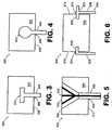
- FIGs. 3 - 6 various techniques can be used for mounting a floatwall panel within a combustion section. Representative techniques are depicted schematically in FIGs. 3 - 6 .
- a representative embodiment of a floatwall panel assembly attachment 300 includes a floatwall panel 302 and a mount 304.
- a slot 306 is formed in a combustor shell side face 308 of the panel that is configured to receive a distal end 310 of the mount.
- the mount is configured as an elongate rail. Although such a rail and corresponding slot can be formed in various complementary shapes and sizes, the rail and slot of this embodiment are configured with a T-shape when viewed in cross-section.
- the rail is positioned to extend outwardly from the wall (not shown) and the panel is slid over the rail, thereby capturing the distal, protruding portion of the rail within the slot.
- more than one slot and rail can be used per panel.
- floatwall panel assembly 400 includes a floatwall panel 402 and a mount 404.
- a slot 406 is formed in a combustor shell side 408 of the panel that is configured to receive a bulbous distal end 410 of the mount.
- the mount also is configured as an elongate rail with a profile that is generally complementary to that of the slot 406.
- the floatwall panel assembly attachment 500 of FIG. 5 incorporates a mount 502 that extends through the floatwall panel.
- the panel 504 includes a mounting hole 506 that extends from a hot section side face 508 to a combustor shell side face 510 of the panel.
- the mounting hole is sized and shaped to receive a screw 512 that mounts the panel to the combustor shell.
- screw 512 incorporates a means for cooling, which in this embodiment includes cooling channels, e.g., channel 514, through which cooling air is routed for cooling the screw.
- various other cooling means can be used for cooling a mount such as one or more features that provide transpiration and/or impingement cooling.
- mounts can be formed of various materials, such as ceramics, nickel alloys, cobalt alloys, molybdenum alloys, niobium alloys, steel alloys and/or combinations thereof, for example.
- floatwall panel assembly attachment 600 includes a floatwall panel 602 and a mount 604 that includes opposing rails 606, 608.
- opposing side walls 610, 612 of the panel incorporate slots 614, 616 that are configured to receive corresponding portions 618, 620 of the rails.
- the rails can incorporate opposing extended portions, such as portions 620 and 622. Such a configuration can enable a rail to be positioned between and mount adjacent floatwall panels.
Landscapes
- Engineering & Computer Science (AREA)
- Chemical & Material Sciences (AREA)
- Ceramic Engineering (AREA)
- Combustion & Propulsion (AREA)
- Mechanical Engineering (AREA)
- General Engineering & Computer Science (AREA)
- Turbine Rotor Nozzle Sealing (AREA)
Claims (18)
- Float-Wandplatte (210) für einen Verbrennungsabschnitt (106) eines Gasturbinentriebwerks (100), Folgendes umfassend:ein poröses Material und dadurch gekennzeichnet, dass das poröse Material einen Porositätsgradienten entlang zumindest einer Länge und einer Breite der Float-Wandplatte aufweist;wobei die Float-Wandplatte eine erste Region (230), eine zweite Region (232) und eine dritte Region (234) aufweist, von denen jede eine Porosität aufweist, die sich von der Porosität einer benachbarten Region unterscheidet;wobei die erste Region einen Bereich mit relativ gleichmäßiger Porosität entlang dessen Länge, Breite und Tiefe umfasst, und wobei die zweite Region eine relativ gleichmäßige Porosität entlang ihrer Länge, Breite und Tiefe aufweist, wobei die Porosität der zweiten Region höher ist als die Porosität, die die erste Region aufweist; undwobei die dritte Region eine erste Schicht (240) und eine zweite Schicht (242) umfasst, wobei die zweite Schicht näher an einem Gasströmungsweg (228) als die erste Schicht angeordnet ist, und wobei die erste Schicht eine höhere Porosität entlang ihrer Länge, Breite und Tiefe aufweist als die zweite Schicht.
- Float-Wandplatte nach Anspruch 1 ferner einen Schlitz (306; 406; 614; 616) umfassend, der in einer Fläche der Platte ausgebildet ist, wobei der Schlitz die Größe und die Form aufweist, um eine Befestigung (212) zum Befestigen der Platte an einem Verbrennungsabschnitt aufzunehmen.
- Float-Wandplattenanordnung für einen Verbrennungsabschnitt (106) eines Gasturbinentriebwerks (100), wobei die Anordnung eine Float-Wandplatte (210) nach Anspruch 1 umfasst:wobei die Platte (210) aus einem porösen Keramikmaterial besteht und der Platte ein Substrat fehlt, das aus einem anderen Material als dem porösen Keramikmaterial für das Tragen des porösen Keramikmaterials ausgebildet ist.
- Anordnung nach Anspruch 3 ferner eine Befestigung (212) umfassend, die angepasst ist, um die Platte in Eingriff zu nehmen und die Platte in einem räumlichen Verhältnis zu einer Oberfläche zu halten, an der die Platte angebracht ist.
- Anordnung nach Anspruch 4, wobei
die Befestigung eine Schiene (304; 404) umfasst; und
die Platte einen Schlitz (306; 406) umfasst, der dazu dient, die Schiene aufzunehmen. - Verbrennungsabschnitt (106) eines Gasturbinentriebwerks (100), Folgendes umfassend:eine Float-Wandplatte (210) nach Anspruch 1 oder 2 und eine Befestigung (212) oder eine Float-Wandplattenanordnung (206) nach Anspruch 4.
- Verbrennungsabschnitt nach Anspruch 6, wobei:der Verbrennungsabschnitt ferner eine Brennkammerschale (204) umfasst; unddie Befestigung (212) angepasst ist, um die Platte in einem räumlichen Verhältnis mit einer Oberfläche der Brennkammerschale zu halten.
- Verbrennungsabschnitt nach Anspruch 7, wobei:die Befestigung eine Schiene (304; 404) umfasst, die an der Brennkammerschale angebracht ist; unddie Platte einen Schlitz (306; 406) umfasst, der dazu dient, die Schiene aufzunehmen.
- Verbrennungsabschnitt nach Anspruch 8, wobei der Schlitz ein länglicher Schlitz ist, der in einer Fläche (308; 408) der Platte (302; 402) ausgebildet ist.
- Verbrennungsabschnitt nach Anspruch 7, wobei:die Befestigung eine erste Schiene (606) und eine zweite Schiene (608) umfasst, von denen jede an der Brennkammerschale angebracht ist, wobei die erste Schiene von der zweiten Schiene beabstandet ist;die Platte einen ersten Schlitz (614), der in einer ersten Seitenwand (610) der Platte angeordnet ist, und einen zweiten Schlitz (616), der in einer zweiten Seitenwand (612) der Platte (602) angeordnet ist, umfasst; undder erste Schlitz die Größe und die Form aufweist, um die erste Schiene aufzunehmen, und der zweite Schlitz die Größe und die Form aufweist, um die zweite Schiene aufzunehmen.
- Verbrennungsabschnitt nach Anspruch 10, wobei die erste Seitenwand (610) und die zweite Seitenwand (612) sich gegenüberliegen.
- Vorrichtung nach Anspruch 4 oder 7, wobei:die Befestigung eine Schraube (512) ist; unddie Platte ein Durchgangsloch (506) umfasst, das sich von einer heißen Abschnittsfläche zu einer Fläche der Brennkammerschale erstreckt, wobei das Durchgangsloch die Größe und die Form aufweist, um die Schraube aufzunehmen.
- Vorrichtung nach Anspruch 4, 5 oder 12, ferner ein Mittel (514) zum Kühlen der Befestigung umfassend.
- Vorrichtung nach Anspruch 13, wobei das Mittel zur Kühlung der Befestigung einen Kühlkanal (514) umfasst.
- Vorrichtung nach einem der vorhergehenden Ansprüche, wobei die Platte eine Region mit einer höheren Porosität als eine benachbarte Region umfasst, wobei der Bereich der höheren Porosität an einem zu erwartenden heißen Punkt des Verbrennungsabschnittes positioniert ist.
- Vorrichtung nach einem der vorhergehenden Ansprüche, wobei der Porositätsgradient derart ist, dass eine Porosität der Platte sich von einer Fläche eines heißen Abschnittes zu einer Fläche der Brennkammerschale der Platte erhöht.
- Gasturbinentriebwerk (100), Folgendes umfassend:einen Verbrennungsabschnitt (106) nach Anspruch 6 und eine Brennkammerschale;wobei die Platte an der Brennkammerschale angebracht ist und davon durch die Befestigung beabstandet ist.
- Gasturbinentriebwerk nach Anspruch 17, wobei der Verbrennungsabschnitt ein vollständig umkreister, ringförmiger Verbrennungsabschnitt ist.
Applications Claiming Priority (1)
| Application Number | Priority Date | Filing Date | Title |
|---|---|---|---|
| US11/775,398 US8800293B2 (en) | 2007-07-10 | 2007-07-10 | Floatwell panel assemblies and related systems |
Publications (2)
| Publication Number | Publication Date |
|---|---|
| EP2017533A1 EP2017533A1 (de) | 2009-01-21 |
| EP2017533B1 true EP2017533B1 (de) | 2016-04-13 |
Family
ID=40039743
Family Applications (1)
| Application Number | Title | Priority Date | Filing Date |
|---|---|---|---|
| EP08252362.2A Not-in-force EP2017533B1 (de) | 2007-07-10 | 2008-07-10 | Float-Wandanordnungen und damit verbundene Systeme |
Country Status (2)
| Country | Link |
|---|---|
| US (1) | US8800293B2 (de) |
| EP (1) | EP2017533B1 (de) |
Families Citing this family (31)
| Publication number | Priority date | Publication date | Assignee | Title |
|---|---|---|---|---|
| US8490399B2 (en) | 2011-02-15 | 2013-07-23 | Siemens Energy, Inc. | Thermally isolated wall assembly |
| US8739547B2 (en) * | 2011-06-23 | 2014-06-03 | United Technologies Corporation | Gas turbine engine joint having a metallic member, a CMC member, and a ceramic key |
| US8997495B2 (en) | 2011-06-24 | 2015-04-07 | United Technologies Corporation | Strain tolerant combustor panel for gas turbine engine |
| US8584470B2 (en) | 2012-02-15 | 2013-11-19 | United Technologies Corporation | Tri-lobed cooling hole and method of manufacture |
| US8850828B2 (en) | 2012-02-15 | 2014-10-07 | United Technologies Corporation | Cooling hole with curved metering section |
| US8683813B2 (en) | 2012-02-15 | 2014-04-01 | United Technologies Corporation | Multi-lobed cooling hole and method of manufacture |
| US8733111B2 (en) | 2012-02-15 | 2014-05-27 | United Technologies Corporation | Cooling hole with asymmetric diffuser |
| US10422230B2 (en) | 2012-02-15 | 2019-09-24 | United Technologies Corporation | Cooling hole with curved metering section |
| US8683814B2 (en) | 2012-02-15 | 2014-04-01 | United Technologies Corporation | Gas turbine engine component with impingement and lobed cooling hole |
| US9422815B2 (en) | 2012-02-15 | 2016-08-23 | United Technologies Corporation | Gas turbine engine component with compound cusp cooling configuration |
| US8572983B2 (en) | 2012-02-15 | 2013-11-05 | United Technologies Corporation | Gas turbine engine component with impingement and diffusive cooling |
| US9416971B2 (en) | 2012-02-15 | 2016-08-16 | United Technologies Corporation | Multiple diffusing cooling hole |
| US8689568B2 (en) | 2012-02-15 | 2014-04-08 | United Technologies Corporation | Cooling hole with thermo-mechanical fatigue resistance |
| US9598979B2 (en) | 2012-02-15 | 2017-03-21 | United Technologies Corporation | Manufacturing methods for multi-lobed cooling holes |
| US8707713B2 (en) | 2012-02-15 | 2014-04-29 | United Technologies Corporation | Cooling hole with crenellation features |
| US9416665B2 (en) | 2012-02-15 | 2016-08-16 | United Technologies Corporation | Cooling hole with enhanced flow attachment |
| US9410435B2 (en) | 2012-02-15 | 2016-08-09 | United Technologies Corporation | Gas turbine engine component with diffusive cooling hole |
| US9279330B2 (en) | 2012-02-15 | 2016-03-08 | United Technologies Corporation | Gas turbine engine component with converging/diverging cooling passage |
| US9284844B2 (en) | 2012-02-15 | 2016-03-15 | United Technologies Corporation | Gas turbine engine component with cusped cooling hole |
| US9482100B2 (en) | 2012-02-15 | 2016-11-01 | United Technologies Corporation | Multi-lobed cooling hole |
| US8763402B2 (en) | 2012-02-15 | 2014-07-01 | United Technologies Corporation | Multi-lobed cooling hole and method of manufacture |
| US8522558B1 (en) | 2012-02-15 | 2013-09-03 | United Technologies Corporation | Multi-lobed cooling hole array |
| US9273560B2 (en) | 2012-02-15 | 2016-03-01 | United Technologies Corporation | Gas turbine engine component with multi-lobed cooling hole |
| US9024226B2 (en) | 2012-02-15 | 2015-05-05 | United Technologies Corporation | EDM method for multi-lobed cooling hole |
| WO2014143209A1 (en) | 2013-03-15 | 2014-09-18 | Rolls-Royce Corporation | Gas turbine engine combustor liner |
| US9879861B2 (en) | 2013-03-15 | 2018-01-30 | Rolls-Royce Corporation | Gas turbine engine with improved combustion liner |
| GB201403404D0 (en) | 2014-02-27 | 2014-04-16 | Rolls Royce Plc | A combustion chamber wall and a method of manufacturing a combustion chamber wall |
| US10234141B2 (en) | 2016-04-28 | 2019-03-19 | United Technoloigies Corporation | Ceramic and ceramic matrix composite attachment methods and systems |
| US10605092B2 (en) | 2016-07-11 | 2020-03-31 | United Technologies Corporation | Cooling hole with shaped meter |
| US10563519B2 (en) * | 2018-02-19 | 2020-02-18 | General Electric Company | Engine component with cooling hole |
| CN108895483B (zh) * | 2018-07-05 | 2023-12-29 | 湖南云顶智能科技有限公司 | 一种火焰稳定装置、燃烧装置及试验方法 |
Family Cites Families (19)
| Publication number | Priority date | Publication date | Assignee | Title |
|---|---|---|---|---|
| DE1626032A1 (de) | 1967-08-31 | 1971-01-14 | Daimler Benz Ag | Thermischer Belastung ausgesetzter und mit einem Gas zu kuehlender Teil eines Gasturbinentriebwerkes |
| US4008568A (en) * | 1976-03-01 | 1977-02-22 | General Motors Corporation | Combustor support |
| JPS5857658B2 (ja) * | 1980-04-02 | 1983-12-21 | 工業技術院長 | セラミツクスによる高熱曝露壁面の熱遮断構造 |
| US4622821A (en) | 1985-01-07 | 1986-11-18 | United Technologies Corporation | Combustion liner for a gas turbine engine |
| US4700544A (en) | 1985-01-07 | 1987-10-20 | United Technologies Corporation | Combustors |
| US4653279A (en) | 1985-01-07 | 1987-03-31 | United Technologies Corporation | Integral refilmer lip for floatwall panels |
| US5129231A (en) | 1990-03-12 | 1992-07-14 | United Technologies Corporation | Cooled combustor dome heatshield |
| US5431020A (en) * | 1990-11-29 | 1995-07-11 | Siemens Aktiengesellschaft | Ceramic heat shield on a load-bearing structure |
| US5623827A (en) | 1995-01-26 | 1997-04-29 | General Electric Company | Regenerative cooled dome assembly for a gas turbine engine combustor |
| DE59907940D1 (de) | 1998-03-10 | 2004-01-15 | Siemens Ag | Brennkammer und verfahren zum betrieb einer brennkammer |
| US6973419B1 (en) | 2000-03-02 | 2005-12-06 | United Technologies Corporation | Method and system for designing an impingement film floatwall panel system |
| GB2373319B (en) * | 2001-03-12 | 2005-03-30 | Rolls Royce Plc | Combustion apparatus |
| US7128532B2 (en) | 2003-07-22 | 2006-10-31 | The Boeing Company | Transpiration cooling system |
| US7146815B2 (en) * | 2003-07-31 | 2006-12-12 | United Technologies Corporation | Combustor |
| EP1508761A1 (de) * | 2003-08-22 | 2005-02-23 | Siemens Aktiengesellschaft | Hitzeschildstein zur Auskleidung einer Brennkammerwand, Brennkammer sowie Gasturbine |
| EP1533113A1 (de) | 2003-11-14 | 2005-05-25 | Siemens Aktiengesellschaft | Hochtemperatur-Schichtsystem zur Wärmeableitung und Verfahren zu dessen Herstellung |
| US20050249602A1 (en) | 2004-05-06 | 2005-11-10 | Melvin Freling | Integrated ceramic/metallic components and methods of making same |
| DE102005036137A1 (de) | 2005-07-26 | 2007-02-01 | Deutsches Zentrum für Luft- und Raumfahrt e.V. | Brennkammer und Verfahren zur Herstellung einer Brennkammer |
| US8171634B2 (en) * | 2007-07-09 | 2012-05-08 | Pratt & Whitney Canada Corp. | Method of producing effusion holes |
-
2007
- 2007-07-10 US US11/775,398 patent/US8800293B2/en active Active
-
2008
- 2008-07-10 EP EP08252362.2A patent/EP2017533B1/de not_active Not-in-force
Also Published As
| Publication number | Publication date |
|---|---|
| US8800293B2 (en) | 2014-08-12 |
| EP2017533A1 (de) | 2009-01-21 |
| US20090013695A1 (en) | 2009-01-15 |
Similar Documents
| Publication | Publication Date | Title |
|---|---|---|
| EP2017533B1 (de) | Float-Wandanordnungen und damit verbundene Systeme | |
| CN100534778C (zh) | 用于散热的高温涂层系统及其制造方法 | |
| CN100402800C (zh) | 合成高温部件及其制造方法 | |
| US9422828B2 (en) | Bi-cast layered wall with a porous element for component cooling | |
| JP4181860B2 (ja) | 断続したリブ付きの熱伝達面を有する部品壁 | |
| US8596963B1 (en) | BOAS for a turbine | |
| EP2354660B1 (de) | Brennkammer mit einem abdichtungselement eines brennkammerwandsegments | |
| US7854122B2 (en) | Cooling method and apparatus | |
| US8016547B2 (en) | Radial inner diameter metering plate | |
| JP4494444B2 (ja) | 被覆タービン翼 | |
| DE102013110381B4 (de) | Heißgaspfadkomponente mit einer Schichtanordnung und Verfahren zur Herstellung einer derartigen Heißgaspfadkomponente | |
| CN107076414A (zh) | 热屏蔽元件和用于其制造的方法 | |
| EP3322881B1 (de) | Turbomaschinenkomponente mit kühlfunktionen und verfahren zur herstellung solch einer turbomaschinenkomponente | |
| EP2354656A2 (de) | Abdichtungselement für Brennkammerwandsegment | |
| US10408090B2 (en) | Gas turbine engine article with panel retained by preloaded compliant member | |
| KR20010039934A (ko) | 기체 냉각제 기류의 냉각 효능 개선 방법 및 관련 물품 | |
| JP2008057534A (ja) | フィルム冷却式スロット付き壁およびその製作方法 | |
| CN107917439B (zh) | 燃烧器后框架冷却 | |
| EP1930546A3 (de) | Schaufel mit Plasma-Generator zum Schutz einer Grenzschicht stromaufwärts einer Filmkühlungsbohrung und entsprechendes Betriebsverfahren | |
| EP3076078B1 (de) | Brennkammerkonfigurationen für einen gasturbinenmotor | |
| JP5271688B2 (ja) | ガスタービン用部材 | |
| EP1659263A3 (de) | Kühlungssystem für eine Turbinenschaufel | |
| JP2010506086A (ja) | タービンエンジン内で使用可能なタービンエーロフォイル用断熱コーティングシステム | |
| US10689984B2 (en) | Cast gas turbine engine cooling components | |
| EP3196329A1 (de) | Hitzeabschirmende beschichtung und turbinenelement |
Legal Events
| Date | Code | Title | Description |
|---|---|---|---|
| PUAI | Public reference made under article 153(3) epc to a published international application that has entered the european phase |
Free format text: ORIGINAL CODE: 0009012 |
|
| AK | Designated contracting states |
Kind code of ref document: A1 Designated state(s): AT BE BG CH CY CZ DE DK EE ES FI FR GB GR HR HU IE IS IT LI LT LU LV MC MT NL NO PL PT RO SE SI SK TR |
|
| AX | Request for extension of the european patent |
Extension state: AL BA MK RS |
|
| 17P | Request for examination filed |
Effective date: 20090421 |
|
| 17Q | First examination report despatched |
Effective date: 20090609 |
|
| AKX | Designation fees paid |
Designated state(s): DE FR GB |
|
| GRAP | Despatch of communication of intention to grant a patent |
Free format text: ORIGINAL CODE: EPIDOSNIGR1 |
|
| INTG | Intention to grant announced |
Effective date: 20151106 |
|
| GRAS | Grant fee paid |
Free format text: ORIGINAL CODE: EPIDOSNIGR3 |
|
| GRAA | (expected) grant |
Free format text: ORIGINAL CODE: 0009210 |
|
| AK | Designated contracting states |
Kind code of ref document: B1 Designated state(s): DE FR GB |
|
| REG | Reference to a national code |
Ref country code: GB Ref legal event code: FG4D |
|
| REG | Reference to a national code |
Ref country code: DE Ref legal event code: R096 Ref document number: 602008043460 Country of ref document: DE |
|
| RAP2 | Party data changed (patent owner data changed or rights of a patent transferred) |
Owner name: UNITED TECHNOLOGIES CORPORATION |
|
| REG | Reference to a national code |
Ref country code: DE Ref legal event code: R097 Ref document number: 602008043460 Country of ref document: DE |
|
| REG | Reference to a national code |
Ref country code: DE Ref legal event code: R119 Ref document number: 602008043460 Country of ref document: DE |
|
| PLBE | No opposition filed within time limit |
Free format text: ORIGINAL CODE: 0009261 |
|
| STAA | Information on the status of an ep patent application or granted ep patent |
Free format text: STATUS: NO OPPOSITION FILED WITHIN TIME LIMIT |
|
| 26N | No opposition filed |
Effective date: 20170116 |
|
| GBPC | Gb: european patent ceased through non-payment of renewal fee |
Effective date: 20160713 |
|
| PG25 | Lapsed in a contracting state [announced via postgrant information from national office to epo] |
Ref country code: FR Free format text: LAPSE BECAUSE OF NON-PAYMENT OF DUE FEES Effective date: 20160801 Ref country code: DE Free format text: LAPSE BECAUSE OF NON-PAYMENT OF DUE FEES Effective date: 20170201 |
|
| REG | Reference to a national code |
Ref country code: FR Ref legal event code: ST Effective date: 20170331 |
|
| PG25 | Lapsed in a contracting state [announced via postgrant information from national office to epo] |
Ref country code: GB Free format text: LAPSE BECAUSE OF NON-PAYMENT OF DUE FEES Effective date: 20160713 |