EP2017627A2 - Détection inductive de rotation - Google Patents
Détection inductive de rotation Download PDFInfo
- Publication number
- EP2017627A2 EP2017627A2 EP08160058A EP08160058A EP2017627A2 EP 2017627 A2 EP2017627 A2 EP 2017627A2 EP 08160058 A EP08160058 A EP 08160058A EP 08160058 A EP08160058 A EP 08160058A EP 2017627 A2 EP2017627 A2 EP 2017627A2
- Authority
- EP
- European Patent Office
- Prior art keywords
- arrangement according
- wheel
- pulse
- coils
- planar
- Prior art date
- Legal status (The legal status is an assumption and is not a legal conclusion. Google has not performed a legal analysis and makes no representation as to the accuracy of the status listed.)
- Withdrawn
Links
- 238000001514 detection method Methods 0.000 title claims abstract description 16
- 230000001939 inductive effect Effects 0.000 title claims description 14
- 230000010355 oscillation Effects 0.000 claims abstract description 7
- 238000005516 engineering process Methods 0.000 claims description 2
- 238000011156 evaluation Methods 0.000 description 9
- 238000005259 measurement Methods 0.000 description 3
- 239000000243 solution Substances 0.000 description 3
- 230000005540 biological transmission Effects 0.000 description 2
- 238000011109 contamination Methods 0.000 description 2
- 239000002245 particle Substances 0.000 description 2
- 241001295925 Gegenes Species 0.000 description 1
- 239000003637 basic solution Substances 0.000 description 1
- 238000005452 bending Methods 0.000 description 1
- 238000013016 damping Methods 0.000 description 1
- 239000000428 dust Substances 0.000 description 1
- 238000002474 experimental method Methods 0.000 description 1
- 238000009434 installation Methods 0.000 description 1
- 239000000463 material Substances 0.000 description 1
- 239000002184 metal Substances 0.000 description 1
- 238000000034 method Methods 0.000 description 1
- 239000003921 oil Substances 0.000 description 1
- 230000000737 periodic effect Effects 0.000 description 1
- 238000004080 punching Methods 0.000 description 1
- 230000002123 temporal effect Effects 0.000 description 1
- XLYOFNOQVPJJNP-UHFFFAOYSA-N water Substances O XLYOFNOQVPJJNP-UHFFFAOYSA-N 0.000 description 1
Images
Classifications
-
- G—PHYSICS
- G01—MEASURING; TESTING
- G01P—MEASURING LINEAR OR ANGULAR SPEED, ACCELERATION, DECELERATION, OR SHOCK; INDICATING PRESENCE, ABSENCE, OR DIRECTION, OF MOVEMENT
- G01P3/00—Measuring linear or angular speed; Measuring differences of linear or angular speeds
- G01P3/42—Devices characterised by the use of electric or magnetic means
- G01P3/44—Devices characterised by the use of electric or magnetic means for measuring angular speed
- G01P3/48—Devices characterised by the use of electric or magnetic means for measuring angular speed by measuring frequency of generated current or voltage
- G01P3/481—Devices characterised by the use of electric or magnetic means for measuring angular speed by measuring frequency of generated current or voltage of pulse signals
- G01P3/488—Devices characterised by the use of electric or magnetic means for measuring angular speed by measuring frequency of generated current or voltage of pulse signals delivered by variable reluctance detectors
-
- G—PHYSICS
- G01—MEASURING; TESTING
- G01P—MEASURING LINEAR OR ANGULAR SPEED, ACCELERATION, DECELERATION, OR SHOCK; INDICATING PRESENCE, ABSENCE, OR DIRECTION, OF MOVEMENT
- G01P13/00—Indicating or recording presence, absence, or direction, of movement
- G01P13/02—Indicating direction only, e.g. by weather vane
- G01P13/04—Indicating positive or negative direction of a linear movement or clockwise or anti-clockwise direction of a rotational movement
Definitions
- the invention relates to an arrangement for inductive speed detection according to the preamble of claim 1.
- Such arrangements are, for example, from the published patent application DE 10 2005 029 764 A1 known.
- the sensor element is designed there as a Hall sensor element. Hall sensor elements are well suited for detecting the variation of a magnetic field and are therefore often used for speed detection. Hall sensor elements are inexpensive to purchase and can also be used at temperatures up to about 160 ° C.
- a disadvantage of the Hall sensor is that it is sensitive to dirt particles. In the worst case, the contamination can lead to a complete failure of the sensor.
- the sensor element may be formed as a magnetoresistive (MR) sensor element.
- the sensor element is designed to be inductive. Also inductive sensor elements are in principle good for detecting the variation of a magnetic field.
- wound coils are used, which bring in addition to a high cost of materials as a major disadvantage with them that they have a depth of several centimeters on average.
- a digital inductive sensor for linear position determination, angle measurement and speed measurement with tooth-shaped pulse wheels is known.
- the measuring coils are flat and resistant in oil, water, dust and in magnetic fields.
- the sensor chip comprises - according to the transformer principle - a transmitting coil and two receiving coils.
- the receiver coils are offset in the direction of movement of the pulse wheel (of the target). The possible distance between the target and the sensor chip is also limited in this arrangement.
- the object of the invention is to overcome the problems of the prior art, ie to provide an arrangement for inductive speed detection, which is insensitive to contamination by particles, which allows a small installation depth and allows a large distance of the encoder.
- the tachometer should also handle high temperatures and high pressures such as in a transmission.
- the basic solution consists in accordance with claim 1 in the use of two planar coils for speed measurement.
- the two coils are arranged so that they are spatially offset in the direction of rotation.
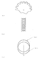
- the basic requirement for this pulse wheel is that it can influence the inductive sensor periodically.
- the structure of the pulse wheel can either resemble that of a gear (see FIG. 1 ) or it can be constructed like a grid (see the schematic representation in FIG. 2 ).
- the impulse wheel need not be encoded to detect which direction it is turning.
- the decisive factor here is that the two planar coils are arranged spatially offset in the direction of rotation.
- the FIG. 3 shows this spatial offset of the two flat coils.
- the coil 1 may be part of an oscillator and the coil 2 may also be part of another oscillator, in each case the oscillator frequencies are determined.
- a frequency evaluation is, due to a higher resolution, more accurate than a conventional voltage
- the coil 1 (and optionally the coil 2) are preferably printed on a printed circuit board, but may also be stamped or made of bent wire, etc.
- the pulse generator impulse wheel
- the sensor no longer yielded usable results due to the further distance.
- planar coils and frequency evaluation counteracts this disadvantage.
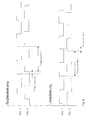
- a direction of rotation detection is provided in a particularly simple manner if the advancement of a tooth or a grating element (in any case the passage of a pulse-causing portion of the Radtoxinss) is first perceived impulsively on a flat coil and then on the other flat coil.
- Fig. 4 It can be seen how the order of the pulse edges reverses with the direction of rotation.
- this direction of rotation detection is not readily supplied, but can be supplemented in a manner alternative to the first solution, namely when the impulse wheel is encoded in the sense of claim 13. Coding means that the individual teeth of the impulse wheel are distinguishable. Then the use for direction detection according to claim 22 is possible.
- the fundamental frequency is 20.0 MHz.
- the pulse temporarily increases this oscillation frequency to 20.2 MHz; i.e. the pulse causes a short-term frequency change of 0.2 MHz (which is very well detectable and attributable to a tooth).
- the frequency increase pulses are constant in the same sense (ie temperature stable and distance compensated); they also merely differ stepwise from tooth to tooth or in their temporal change.
- the evaluation circuit can then additionally locate each individual tooth in succession, i. recognize the direction of rotation and / or the rough angular position from this individualization.
Landscapes
- Physics & Mathematics (AREA)
- General Physics & Mathematics (AREA)
- Transmission And Conversion Of Sensor Element Output (AREA)
- Indicating Or Recording The Presence, Absence, Or Direction Of Movement (AREA)
Applications Claiming Priority (1)
| Application Number | Priority Date | Filing Date | Title |
|---|---|---|---|
| DE102007033745.2A DE102007033745B4 (de) | 2007-07-19 | 2007-07-19 | Induktive Drehzahlerkennung |
Publications (2)
| Publication Number | Publication Date |
|---|---|
| EP2017627A2 true EP2017627A2 (fr) | 2009-01-21 |
| EP2017627A3 EP2017627A3 (fr) | 2013-05-22 |
Family
ID=39877735
Family Applications (1)
| Application Number | Title | Priority Date | Filing Date |
|---|---|---|---|
| EP08160058.7A Withdrawn EP2017627A3 (fr) | 2007-07-19 | 2008-07-10 | Détection inductive de rotation |
Country Status (5)
| Country | Link |
|---|---|
| US (1) | US8248064B2 (fr) |
| EP (1) | EP2017627A3 (fr) |
| JP (1) | JP5222052B2 (fr) |
| CN (1) | CN101452006A (fr) |
| DE (1) | DE102007033745B4 (fr) |
Cited By (1)
| Publication number | Priority date | Publication date | Assignee | Title |
|---|---|---|---|---|
| DE102009045676A1 (de) | 2009-10-14 | 2011-04-28 | Zf Friedrichshafen Ag | Verfahren und Vorrichtung zur induktiven Bestimmung der absoluten Position eines an einem Impulsgeber angeordneten Impulsgeberelements |
Families Citing this family (6)
| Publication number | Priority date | Publication date | Assignee | Title |
|---|---|---|---|---|
| DE102008056700B4 (de) | 2008-11-11 | 2013-02-28 | Zf Friedrichshafen Ag | Drehzahlsensor zum Ermitteln von "langsamen (Nulldrehzahl) und schnellen" Drehzahlen sowie zur gleichzeitigen Ermittlung der Drehrichtung |
| DE102012014493B4 (de) * | 2012-07-23 | 2020-07-09 | Epro Gmbh | Verfahren und Vorrichtung zur redundanten Erkennung einer Drehrichtung |
| US9285386B2 (en) * | 2013-12-06 | 2016-03-15 | Rosemount Aerospace Inc. | Inductive rotational speed sensors |
| GB2524061B (en) * | 2014-03-13 | 2018-08-29 | Salunda Ltd | Sensor arrangement for a rotatable element |
| FR3051552B1 (fr) * | 2016-05-18 | 2018-05-25 | Continental Automotive France | Capteur de position inductif lineaire pour une mesure angulaire d'une piece mecanique en rotation |
| CN111024977B (zh) * | 2019-12-26 | 2021-07-02 | 天津津航计算技术研究所 | 一种基于电涡流原理速度传感器的信号检测方法 |
Citations (2)
| Publication number | Priority date | Publication date | Assignee | Title |
|---|---|---|---|---|
| US20060225358A1 (en) * | 2005-04-11 | 2006-10-12 | Haag Ronald H | Apparatus and method for providing a drive device for a vehicle door |
| DE102005029764A1 (de) | 2005-06-27 | 2007-01-04 | Siemens Ag | Sensor zur Messung der Drehzahl einer Turbowelle |
Family Cites Families (20)
| Publication number | Priority date | Publication date | Assignee | Title |
|---|---|---|---|---|
| US4162153A (en) * | 1976-04-12 | 1979-07-24 | Air Products And Chemicals, Inc. | High nitrogen and phosphorous content biomass produced by treatment of a BOD-containing material |
| US4142153A (en) * | 1977-02-17 | 1979-02-27 | Sperry Rand Corporation | Tachometer for measuring speed and direction of shaft rotation with a single sensing element |
| DE2847522A1 (de) | 1978-11-02 | 1980-05-14 | Bosch Gmbh Robert | Induktiver geber und auswerteschaltung hierzu |
| DE2939643A1 (de) | 1979-09-29 | 1981-04-16 | Robert Bosch Gmbh, 7000 Stuttgart | Induktiver drehzahl- oder drehwinkelgeber |
| US4331917A (en) * | 1979-12-13 | 1982-05-25 | Caterpillar Tractor Co. | Speed and direction sensing circuit |
| US4355364A (en) * | 1980-02-04 | 1982-10-19 | Caterpillar Tractor Co. | Velocity sensing system |
| DE3242109A1 (de) | 1982-11-13 | 1984-05-17 | Robert Bosch Gmbh, 7000 Stuttgart | Vorrichtung zur erfassung der drehzahl eines rotierenden teils |
| US4947116A (en) * | 1988-09-02 | 1990-08-07 | Hamilton Standard Controls, Inc. | Inductive speed sensor employing phase shift |
| DE9216703U1 (de) | 1992-12-08 | 1993-02-25 | AB Elektronik GmbH, 4712 Werne | Anordnung zur Erfassung der Position rotierender Wellen |
| JPH0759318A (ja) * | 1993-08-09 | 1995-03-03 | Sankyo Seiki Mfg Co Ltd | 周波数発電機 |
| DE4431640A1 (de) | 1993-09-17 | 1995-04-06 | Luk Getriebe Systeme Gmbh | Fahrzeug mit hydrodynamischem Drehmomentwandler sowie Verfahren zum Steuern eines Drehmomenten-Übertragungssystems mit einem Drehmomentwandler |
| DE4445378A1 (de) | 1994-12-20 | 1996-06-27 | A B Elektronik Gmbh | Verfahren und Vorrichtung zur Erfassung der Winkelposition einer rotierenden Welle |
| CH690934A5 (fr) * | 1996-04-29 | 2001-02-28 | Suisse Electronique Microtech | Dispositif de détection de position et de mouvement à variation de champ magnétique. |
| DE19745236C2 (de) * | 1997-10-13 | 2000-12-21 | Texas Instruments Deutschland | Detektor zur Bestimmung der Drehgeschwindigkeit und Drehrichtung |
| JP2001083168A (ja) * | 1999-09-16 | 2001-03-30 | Suzuki Motor Corp | 推進装置の回転検出装置 |
| DE10011820B4 (de) * | 2000-03-10 | 2012-01-12 | Schaeffler Technologies Gmbh & Co. Kg | Messeinrichtung für Wälzlager |
| DE10114858A1 (de) | 2001-03-26 | 2002-10-17 | A B Elektronik Gmbh | Kurbelwellensensor-IC |
| JP2003058976A (ja) * | 2001-06-04 | 2003-02-28 | Nsk Ltd | ワイヤレスセンサ、転がり軸受装置、管理装置、及び監視装置 |
| DE10130572B4 (de) * | 2001-06-27 | 2010-01-07 | Ifm Electronic Gmbh | Induktiver Wegsensor zur Bestimmung der Position eines Beeinflussungselements und Verfahren zur Bestimmung der Position eines Beeinflussungselements mit einem induktiven Wegsensor |
| FR2841990B1 (fr) * | 2002-07-02 | 2005-07-29 | Skf Ab | Dispositif de palier a roulement instrumente et moteur electrique ainsi equipe |
-
2007
- 2007-07-19 DE DE102007033745.2A patent/DE102007033745B4/de not_active Expired - Fee Related
-
2008
- 2008-05-28 US US12/154,940 patent/US8248064B2/en active Active
- 2008-07-10 EP EP08160058.7A patent/EP2017627A3/fr not_active Withdrawn
- 2008-07-18 CN CNA2008101769523A patent/CN101452006A/zh active Pending
- 2008-07-22 JP JP2008188164A patent/JP5222052B2/ja not_active Expired - Fee Related
Patent Citations (2)
| Publication number | Priority date | Publication date | Assignee | Title |
|---|---|---|---|---|
| US20060225358A1 (en) * | 2005-04-11 | 2006-10-12 | Haag Ronald H | Apparatus and method for providing a drive device for a vehicle door |
| DE102005029764A1 (de) | 2005-06-27 | 2007-01-04 | Siemens Ag | Sensor zur Messung der Drehzahl einer Turbowelle |
Cited By (1)
| Publication number | Priority date | Publication date | Assignee | Title |
|---|---|---|---|---|
| DE102009045676A1 (de) | 2009-10-14 | 2011-04-28 | Zf Friedrichshafen Ag | Verfahren und Vorrichtung zur induktiven Bestimmung der absoluten Position eines an einem Impulsgeber angeordneten Impulsgeberelements |
Also Published As
| Publication number | Publication date |
|---|---|
| US20090021243A1 (en) | 2009-01-22 |
| JP2009025310A (ja) | 2009-02-05 |
| JP5222052B2 (ja) | 2013-06-26 |
| EP2017627A3 (fr) | 2013-05-22 |
| US8248064B2 (en) | 2012-08-21 |
| CN101452006A (zh) | 2009-06-10 |
| DE102007033745B4 (de) | 2014-07-24 |
| DE102007033745A1 (de) | 2009-01-29 |
Similar Documents
| Publication | Publication Date | Title |
|---|---|---|
| EP2225142B1 (fr) | Arrangement de detection de l'angle de direction a mesure absolue | |
| EP2564164B1 (fr) | Système de mesure de longueur magnétique, procédé de mesure de longueur ainsi que procédé de fabrication d'un système de mesure de longueur magnétique | |
| EP2017627A2 (fr) | Détection inductive de rotation | |
| EP0938646B1 (fr) | Systemes pour detecter un mouvement rotatif ou translatoire | |
| DE102014208642A1 (de) | Sensoranordnung zur Erfassung von Drehwinkeln an einem rotierenden Bauteil in einem Fahrzeug | |
| DE102005031086A1 (de) | Sensoranordnung zur Erfassung eines Differenzwinkels | |
| DE102015122154A1 (de) | Vorrichtung zur Feststellung externer magnetischer Streufelder auf einen Magnetfeldsensor | |
| DE102013224098A1 (de) | Sensoranordnung zur Erfassung von Drehwinkeln an einem rotierenden Bauteil in einem Fahrzeug | |
| DE102019127297A1 (de) | Sensorvorrichtung zur Erfassung der Drehwinkelstellung einer drehbeweglichen Welle sowie Lenkungsanordnung eines Fahrzeugs | |
| EP1222471A1 (fr) | Systeme de mesure avec element de mesure d'acceleration et element de mesure de position | |
| DE102018220671A1 (de) | Multiturn-Drehgeber | |
| EP2126517B1 (fr) | Capteur de déplacement incrémentiel inductif et procédé de détermination du décalage d'un premier objet par rapport à un deuxième objet | |
| DE102020108981A1 (de) | Sensoranordnung zur Erfassung der absoluten Winkelposition eines Lenkelements | |
| WO2021052525A1 (fr) | Ensemble capteur pour capturer un couple et une position angulaire d'un arbre rotatif | |
| DE102010051500A1 (de) | kämmende Codierzahnrad- und Sensoranordnung | |
| DE102020108982A1 (de) | Sensoranordnung mit einem vollständig redundanten Messsystem zur Erfassung der absoluten Winkelposition eines Lenkelements | |
| DE102017122071A1 (de) | Verstelleinrichtung und Verfahren zum Einstellen eines Spaltmaßes einer Rotationsstanzvorrichtung | |
| AT521356B1 (de) | Druckdifferenzaufnehmer für ein Durchflussmessgerät sowie Durchflussmessgerät | |
| EP2343506A2 (fr) | Dispositif de mesure de longueur | |
| EP2116814B1 (fr) | Dispositif de mesure destiné à la détermination d'une position et/ou d'une vitesse | |
| DE2521163B1 (de) | Einrichtung zur ermittlung einer der drehzahl oder dem drehwinkel einer achse entsprechenden groesse | |
| DE10354469B4 (de) | Vorrichtung zum Messen des Drehwinkels eines Drehkörpers | |
| EP2028451B1 (fr) | Détecteur inductif avec un noyaux de bobine à la forme d'étapes | |
| DE60034471T2 (de) | Elektronisches lenksäulenmodul | |
| DE102022114508A1 (de) | Induktiver Linearwegsensor sowie Fahrzeug mit einem induktiven Linearwegsensor |
Legal Events
| Date | Code | Title | Description |
|---|---|---|---|
| PUAI | Public reference made under article 153(3) epc to a published international application that has entered the european phase |
Free format text: ORIGINAL CODE: 0009012 |
|
| 17P | Request for examination filed |
Effective date: 20080710 |
|
| AK | Designated contracting states |
Kind code of ref document: A2 Designated state(s): AT BE BG CH CY CZ DE DK EE ES FI FR GB GR HR HU IE IS IT LI LT LU LV MC MT NL NO PL PT RO SE SI SK TR |
|
| AX | Request for extension of the european patent |
Extension state: AL BA MK RS |
|
| RAP1 | Party data changed (applicant data changed or rights of an application transferred) |
Owner name: ZF ELECTRONICS GMBH |
|
| RAP1 | Party data changed (applicant data changed or rights of an application transferred) |
Owner name: ZF FRIEDRICHSHAFEN AG |
|
| PUAL | Search report despatched |
Free format text: ORIGINAL CODE: 0009013 |
|
| AK | Designated contracting states |
Kind code of ref document: A3 Designated state(s): AT BE BG CH CY CZ DE DK EE ES FI FR GB GR HR HU IE IS IT LI LT LU LV MC MT NL NO PL PT RO SE SI SK TR |
|
| AX | Request for extension of the european patent |
Extension state: AL BA MK RS |
|
| RIC1 | Information provided on ipc code assigned before grant |
Ipc: G01P 13/04 20060101ALI20130412BHEP Ipc: G01P 3/488 20060101AFI20130412BHEP |
|
| AKX | Designation fees paid |
Designated state(s): AT BE BG CH CY CZ DE DK EE ES FI FR GB GR HR HU IE IS IT LI LT LU LV MC MT NL NO PL PT RO SE SI SK TR |
|
| 17Q | First examination report despatched |
Effective date: 20170131 |
|
| STAA | Information on the status of an ep patent application or granted ep patent |
Free format text: STATUS: THE APPLICATION IS DEEMED TO BE WITHDRAWN |
|
| 18D | Application deemed to be withdrawn |
Effective date: 20170613 |