EP2017803A1 - Système de conservation des fonctions et de sécurisation actif pour réseaux de haut-parleurs d'alarmes dans une technique de conduite annulaire à deux fils - Google Patents
Système de conservation des fonctions et de sécurisation actif pour réseaux de haut-parleurs d'alarmes dans une technique de conduite annulaire à deux fils Download PDFInfo
- Publication number
- EP2017803A1 EP2017803A1 EP07013864A EP07013864A EP2017803A1 EP 2017803 A1 EP2017803 A1 EP 2017803A1 EP 07013864 A EP07013864 A EP 07013864A EP 07013864 A EP07013864 A EP 07013864A EP 2017803 A1 EP2017803 A1 EP 2017803A1
- Authority
- EP
- European Patent Office
- Prior art keywords
- module
- loudspeaker
- circuit
- mode switching
- loop
- Prior art date
- Legal status (The legal status is an assumption and is not a legal conclusion. Google has not performed a legal analysis and makes no representation as to the accuracy of the status listed.)
- Granted
Links
Images


Classifications
-
- G—PHYSICS
- G08—SIGNALLING
- G08B—SIGNALLING SYSTEMS, e.g. PERSONAL CALLING SYSTEMS; ORDER TELEGRAPHS; ALARM SYSTEMS
- G08B29/00—Checking or monitoring of signalling or alarm systems; Prevention or correction of operating errors, e.g. preventing unauthorised operation
- G08B29/16—Security signalling or alarm systems, e.g. redundant systems
-
- G—PHYSICS
- G08—SIGNALLING
- G08B—SIGNALLING SYSTEMS, e.g. PERSONAL CALLING SYSTEMS; ORDER TELEGRAPHS; ALARM SYSTEMS
- G08B25/00—Alarm systems in which the location of the alarm condition is signalled to a central station, e.g. fire or police telegraphic systems
- G08B25/01—Alarm systems in which the location of the alarm condition is signalled to a central station, e.g. fire or police telegraphic systems characterised by the transmission medium
- G08B25/04—Alarm systems in which the location of the alarm condition is signalled to a central station, e.g. fire or police telegraphic systems characterised by the transmission medium using a single signalling line, e.g. in a closed loop
-
- G—PHYSICS
- G08—SIGNALLING
- G08B—SIGNALLING SYSTEMS, e.g. PERSONAL CALLING SYSTEMS; ORDER TELEGRAPHS; ALARM SYSTEMS
- G08B3/00—Audible signalling systems, e.g. audible personal calling systems
- G08B3/10—Audible signalling systems, e.g. audible personal calling systems using electric transmission; using electromagnetic transmission
-
- G—PHYSICS
- G08—SIGNALLING
- G08B—SIGNALLING SYSTEMS, e.g. PERSONAL CALLING SYSTEMS; ORDER TELEGRAPHS; ALARM SYSTEMS
- G08B7/00—Signalling systems according to two or more of groups G08B3/00 - G08B6/00
- G08B7/06—Signalling systems according to two or more of groups G08B3/00 - G08B6/00 using electric transmission, e.g. involving audible and visible signalling through the use of sound and light sources
-
- H—ELECTRICITY
- H04—ELECTRIC COMMUNICATION TECHNIQUE
- H04R—LOUDSPEAKERS, MICROPHONES, GRAMOPHONE PICK-UPS OR LIKE ACOUSTIC ELECTROMECHANICAL TRANSDUCERS; ELECTRIC HEARING AIDS; PUBLIC ADDRESS SYSTEMS
- H04R29/00—Monitoring arrangements; Testing arrangements
- H04R29/007—Monitoring arrangements; Testing arrangements for public address systems
-
- H—ELECTRICITY
- H04—ELECTRIC COMMUNICATION TECHNIQUE
- H04R—LOUDSPEAKERS, MICROPHONES, GRAMOPHONE PICK-UPS OR LIKE ACOUSTIC ELECTROMECHANICAL TRANSDUCERS; ELECTRIC HEARING AIDS; PUBLIC ADDRESS SYSTEMS
- H04R27/00—Public address systems
Definitions
- the invention relates to an active function maintenance and security system for alarming loudspeaker networks.
- a failure of a loudspeaker circuit must not lead to a complete failure of the supply of the loudspeaker area (point 4.1-g in EN 60 849).
- the monitoring should indicate the failure ... of a loudspeaker circuit. (Point 4.1 in EN 60 849: note 1)
- the aim of the invention is to significantly reduce and simplify their use both the previously required installation effort, as well as to ensure a timely unrestricted and independent of the fire temperature and the installation material used functional integrity of the alarm.
- the tolerance-sensitive loudspeaker circuit monitoring in the central device can be omitted.
- each error is registered and reacted to it at the same time.
- the affected loudspeaker or cable section is isolated from the unaffected parts of the system and a two-way supply of the faulty network is established, as in the case of a failure due to interruption, and a fault is registered centrally.
- the malfunctioning alarming loudspeaker network automatically re-operates with the exception of the defective part.
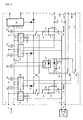
- FIG. 1 shows the basic structure for the alarming loudspeaker network with active functional maintenance system on a two-wire loop basis.
- An operating voltage (for example 24V) is applied to 1-2, the amplifier output with potential-free output transformer to 3-4 and the forward line 5-6 and the return line 7-8 to the infeed and mode switching module FIG. 2 connected.
- the required function maintenance and protection modules FIG. 3 are connected in series and each have a speaker output 55-56 to connect the speaker.
- the module FIG. 3 each housed in the speaker cabinet or a separate installation junction box in the speaker room.
- the last module FIG. 3 becomes on another, spatially not the same route back to the feed and mode switching module FIG. 2 recycled.
- electronics with fault alarm contact outputs 34 are also installed for error message forwarding.
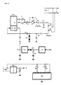
- FIG. 2 shows the principle of the central interface as a feed and mode switching module for loop alarming loudspeaker networks.
- At 1-2 is the operating voltage (usually 24V).
- At 3-4 is the amplifier output (usually 100V).
- the outgoing line and at 7-8 the return line of the loudspeaker loop is connected. There are still various connections for the fault message output and a reset input for resetting correctly latched, stored fault messages.
- the operating voltage is applied.
- the DC-DC converters 9 and 10 each generate a 24V output voltage.
- Relays 11 and 12 energize and switch over with their contacts. This puts each converter on its normal workstation.
- the two voltage outputs are combined to form an operating voltage for the floating control functions of the electronics 17 and 18.
- About the switched contacts 11 and 12 and the 5W resistors (22 ohms) 19 and 20 are the two Electrolytic capacitors (10,000 uF) 21 and 22 pre-charged to avoid a transformer short-circuit.
- the reset relay 33 is set.
- relay 30 can not be energized, although opto-coupler relay 29 could not attract across 7-8 due to lack of voltage feedback, and contact 29 is therefore closed.
- the control electronics 17 and 18 pull the relays 23 and 24 and bridge the resistors 19 and 20, since now the capacitors 21 and 22 are pre-charged.
- the relays 25 and 26 drop off again.
- the full voltage of converter 9 is thus present across the closed contact at the forward output 5-6 and the loop is energized. This builds up the error-free loop through the external speaker modules and must eventually arrive at the return line input 7-8 again.
- the fault signaling logic 30 switches off, and a few seconds later the fault message readiness switches on. This would initially allow the two-way function as needed and then issued from this point any errors as a message.
- both the loop supply voltage 24V and the 100V audio frequency voltage are available.
- the return line 7-8 is connected as input to optocoupler relay 29, which has attracted.
- the externally located loudspeaker modules respond and switch off the shorted section to disconnect the line. Miscellaneous Behavior of the central module as in a normal interruption.
- the external loudspeaker modules briefly disconnected the loop and then rebuilt the loop. Only the first module before the short circuit separates the loop from the short circuit.
- the electronics 17 registers a voltage dip by the short circuit on the outgoing line 5-6 and immediately switches relay 25. This opens contact 25 and the voltage of the converter 9 is through the resistor 31 (4.7 kohm / 5W) protected against short circuit at output 5-6. Likewise, at the same time the amplifier output is protected by the resistor 31 from shorting to 5-6.
- the electronics 17 only switches the relay 25 off again when it receives a voltage again via the resistor 31, that is to say after the short circuit has been eliminated.
- the module remains in the two-way state until the relay 30 drops again when the reset 33 is triggered after short-circuit removal.
- the external loudspeaker modules briefly disconnected the loop and then rebuilt the loop. Only the last module before the short circuit separates the loop from the short circuit.
- the electronics 18 registers a voltage dip through the short circuit at the return line 7-8 and immediately switches relay 26. This opens contact 26 and the voltage of the converter 10 is through the resistor 32 (4.7 kohm / 5W) protected against short circuit at output 7-8.
- the amplifier output is protected by resistor 32 from shorting at 7-8.
- the electronics 18 switches off the relay 26 again only when it receives a voltage again via the resistor 32, ie after Elimination of the short circuit.
- the module remains in the two-way state until the relay 30 drops again when the reset 33 is triggered after short-circuit removal.
- the converters are permanently short-circuit proof and generously designed according to the expected current drain (up to 1A, depending on the number of external speaker modules).
- the amplifier output voltage up to 100V - audio frequency AC voltage
- the two transducers 9-10 the capacitors 21 and 22.
- a permanent operating voltage for working in the potential-free electronics is created.
- Parallel to the converter 9 is the relay 11 and parallel to the converter 10, the relay 12. If a transducer voltage is present, then pull these relays and the output voltage of converter 9 is connected via the contact 11 to Hin effetsausgang from converter 10 via the contact 12 for provided the second channel. If one of the two transformers fails, its relay (11 or 12) drops out and switches the respective channel to the still functioning converter with the aid of the contacts (11 or 12).
- FIG. 3 shows the principle of the function preservation backup module, which is in practice at the respective alarm loudspeaker and divided the two-wire loop into serial sections, which are either turned on or locked.
- Throttle 58 in conjunction with capacitor 64 (220uF), cuts off an additional 100V AC incoming voltage on transmission 51-52, as well as choke 62 and capacitor 65 (220uF).
- the diodes 66 and 67 connected in parallel to the capacitors 64 and 65 serve as polarity protection for these capacitors. Since the series components are relatively high impedance (chokes about 300 ohms, 100V speakers 50 ... 500 ohms), the internal operating voltage 68 builds up slowly (in about 1 second) until it reaches its full height. Therefore, a threshold circuit 69 is connected to the operating voltage, which only turns on its output 71 when it reaches a voltage sufficient for the 24V relay 70 with sufficient certainty of over 20V. Before, however, a voltage of at least 5V must still be present at the inputs 73 and 74 at the NAND gate 72, before the arrival of the voltage 71 can cause the NAND element 72 to attract the relay 70.
- the operating voltage 68 drops due to the load from the relay 70 to a safe for the relay holding voltage of about 12V.
- the threshold switch 69 is designed to be at turns on over 20V and then holds itself until it is reset by another input 73 from the NAND gate 72 when one of the voltages 73 or 74 after the relay suit was no longer present.
- the relay now pulls and remains energized.
- the two contacts 75 and 76 switch over.
- the speaker 55-56 is switched to 52-54 via the fuse 57 and the bipolar electrolytic capacitor 77 (10 ⁇ F), thus obtaining the audio frequency voltage of 51-52.
- Contact 76 bypasses resistor 61 and turns the loop on by connecting 51 and 53 (to the next module or as return). Now normal operation is on.
- the loop break causes no change from the normal operating state on this module. It is only registered in the central module, as there at the return line input nothing arrives.
- the speaker 55-56 is above 57 and 77 via the closed contacts 75-76 parallel to 61 in series between 51 and 53. It does not matter if the short circuit takes place at 51-52 or 53-54.
- the loop is interrupted for the central module.
- the fuse 57 is triggered by the audio frequency 100V (distance from 51 via 55-56, capacitor 77, contact 75 to 52). In this case, then a fuse break is generated again with fuse melting.
- FIG. 4 shows the earth fault monitoring for the central feed and mode switching module FIG. 2 .
- the monitoring may not detect ground fault resistors by DC voltage, since no fixed potential reference can be assumed due to the potential-free 24 V DC voltage on the loop and potential-free.
- the circuit must also be immune, so that no false triggering can take place.
- Higher measuring frequencies could emit interfering radiation or be influenced by the inaudible pilot tone frequency (20 to 25 kHz) of the monitored 100V amplifiers, because unbalance is measured against earth.
- the speaker wires are sampled only briefly for measurement for several reasons.
- a PLL circuit consists of a generator whose frequency is equal to the evaluation frequency of its detector circuit. If the generator frequency is then fed back to the detector input via a defined adjustable threshold circuit, the PLL circuit recognizes its own frequency and switches its evaluation output. If the level of the detector input drops below its threshold, the evaluation input responds immediately to an interruption. This happens much faster than if the PLL had to catch an offered frequency first. At the same time, in principle, it does not matter which PLL frequency it is, it just has to be its own.
- the measurements can not be made simultaneously on both wires of a loudspeaker line, the measurements must be made one after the other. According to the regulations, a measuring process must be carried out on every wire every 100 seconds at the latest. As measuring time, 2 seconds have proven sufficient. In order not to burden the wires with earth due to the measuring process and at the same time to protect the measuring circuit from possible overvoltages up to 100V ⁇ in the event of a fault, the control circuit is connected to high impedance.
- the PLL generator output 81 is fed via a level regulator 82 to an output amplifier and impedance converter 83, which are strongly counter-balanced for harmonics.
- the output capacitor 84 is followed by a high-impedance low pass 85 (47 kOhm) for further harmonic removal.
- This is followed by another high-impedance low pass 86 (130 kOhm) for the detector input 89, which is preceded by the DC voltage cutoff capacitor 87.
- an overvoltage limitation 88 consisting of two Zener diodes 10V connected in opposition to each other.
- the evaluation result appears, which normally indicates a detected frequency by outputting a voltage.
- This voltage is passed through a delay RC element 91, which bridges momentary power interruptions (up to 1/2 second).
- the measuring cycle is generated via a slow-running ring counter 98.
- a 10-stage ring counter would make sense. It advances every 9 seconds and switches the connected relay (here only 99-100) for 2 seconds each. With four modules FIG. 2 That would be eight relays plus the two remaining free steps of the ring counter, which could be used to check the operation.
- fault storage 94 bridges a time of 120 seconds, the fault message would be present for at least this time if a single acquisition or an existing fault would stand still despite the cycle.
- the operating voltage for the ground fault check is generated by a separate DC-DC converter from the operating voltage of FIG. 2 generated and is grounded.
Landscapes
- Physics & Mathematics (AREA)
- General Physics & Mathematics (AREA)
- Engineering & Computer Science (AREA)
- Computer Security & Cryptography (AREA)
- Emergency Management (AREA)
- Business, Economics & Management (AREA)
- Electromagnetism (AREA)
- Health & Medical Sciences (AREA)
- General Health & Medical Sciences (AREA)
- Otolaryngology (AREA)
- Acoustics & Sound (AREA)
- Signal Processing (AREA)
- Alarm Systems (AREA)
- Small-Scale Networks (AREA)
Priority Applications (2)
| Application Number | Priority Date | Filing Date | Title |
|---|---|---|---|
| EP07013864A EP2017803B1 (fr) | 2007-07-16 | 2007-07-16 | Système de conservation des fonctions et de sécurisation actif pour réseaux de haut-parleurs d'alarmes dans une technique de conduite annulaire à deux fils |
| AT07013864T ATE515758T1 (de) | 2007-07-16 | 2007-07-16 | Aktives funktionserhaltungs- und sicherungssystem für alarmierungs-lautsprechernetze in zweidraht- ringleitungstechnik |
Applications Claiming Priority (1)
| Application Number | Priority Date | Filing Date | Title |
|---|---|---|---|
| EP07013864A EP2017803B1 (fr) | 2007-07-16 | 2007-07-16 | Système de conservation des fonctions et de sécurisation actif pour réseaux de haut-parleurs d'alarmes dans une technique de conduite annulaire à deux fils |
Publications (2)
| Publication Number | Publication Date |
|---|---|
| EP2017803A1 true EP2017803A1 (fr) | 2009-01-21 |
| EP2017803B1 EP2017803B1 (fr) | 2011-07-06 |
Family
ID=38823602
Family Applications (1)
| Application Number | Title | Priority Date | Filing Date |
|---|---|---|---|
| EP07013864A Revoked EP2017803B1 (fr) | 2007-07-16 | 2007-07-16 | Système de conservation des fonctions et de sécurisation actif pour réseaux de haut-parleurs d'alarmes dans une technique de conduite annulaire à deux fils |
Country Status (2)
| Country | Link |
|---|---|
| EP (1) | EP2017803B1 (fr) |
| AT (1) | ATE515758T1 (fr) |
Cited By (10)
| Publication number | Priority date | Publication date | Assignee | Title |
|---|---|---|---|---|
| WO2011023133A1 (fr) * | 2009-08-29 | 2011-03-03 | Chan Ka Yin Victor | Procédé et dispositif de protection de sécurité personnelle ou de sécurité de biens |
| DE102010047220A1 (de) * | 2010-10-04 | 2012-04-05 | Novar Gmbh | Verfahren zum Betreiben einer Sprachdurchsageanlage |
| NL2006469C2 (en) * | 2011-03-25 | 2012-09-26 | Astrea Intellectueel Eigendomsrecht B V | Isolator device for passing through a signal. |
| WO2012134273A1 (fr) * | 2011-03-25 | 2012-10-04 | Astrea Intellectueel Eigendomsrecht B.V. | Dispositif d'isolateur pour traverser un signal |
| WO2013186823A1 (fr) * | 2012-06-15 | 2013-12-19 | Toa Corporation | Système de sonorisation et dispositif de commande pour système de sonorisation |
| US9197339B2 (en) | 2011-03-25 | 2015-11-24 | Astrea Intellectueel Eigendomsrecht B.V. | Isolator device for passing through a signal |
| CN105425645A (zh) * | 2015-12-25 | 2016-03-23 | 海宁市引领知识产权咨询服务有限公司 | 一种机械厂智能安全控制装置 |
| CN106099156A (zh) * | 2016-06-20 | 2016-11-09 | 襄城县创世纪科技咨询有限公司 | 一种新能源电池装配装置 |
| WO2018187269A1 (fr) * | 2017-04-05 | 2018-10-11 | Carrier Corporation | Supervision électrique active d'interface audio |
| EP3731539A4 (fr) * | 2017-12-22 | 2021-08-04 | Toa Corporation | Système de diffusion |
Families Citing this family (1)
| Publication number | Priority date | Publication date | Assignee | Title |
|---|---|---|---|---|
| CN105389909A (zh) * | 2015-12-25 | 2016-03-09 | 海宁市引领知识产权咨询服务有限公司 | 一种机电设备的安全警示装置 |
Citations (3)
| Publication number | Priority date | Publication date | Assignee | Title |
|---|---|---|---|---|
| US3876983A (en) * | 1974-04-29 | 1975-04-08 | Ibm | Synchronous disconnection and rearrangement |
| DE3347609A1 (de) | 1983-12-30 | 1985-07-11 | Müller Verkehrstechnik, 7306 Denkendorf | Kommunikations- und ueberwachungssystem fuer verkehrstechnik |
| WO2006050754A2 (fr) * | 2004-11-09 | 2006-05-18 | Robert Bosch Gmbh | Systeme de diffusion publique |
-
2007
- 2007-07-16 AT AT07013864T patent/ATE515758T1/de active
- 2007-07-16 EP EP07013864A patent/EP2017803B1/fr not_active Revoked
Patent Citations (3)
| Publication number | Priority date | Publication date | Assignee | Title |
|---|---|---|---|---|
| US3876983A (en) * | 1974-04-29 | 1975-04-08 | Ibm | Synchronous disconnection and rearrangement |
| DE3347609A1 (de) | 1983-12-30 | 1985-07-11 | Müller Verkehrstechnik, 7306 Denkendorf | Kommunikations- und ueberwachungssystem fuer verkehrstechnik |
| WO2006050754A2 (fr) * | 2004-11-09 | 2006-05-18 | Robert Bosch Gmbh | Systeme de diffusion publique |
Cited By (13)
| Publication number | Priority date | Publication date | Assignee | Title |
|---|---|---|---|---|
| WO2011023133A1 (fr) * | 2009-08-29 | 2011-03-03 | Chan Ka Yin Victor | Procédé et dispositif de protection de sécurité personnelle ou de sécurité de biens |
| DE102010047220A1 (de) * | 2010-10-04 | 2012-04-05 | Novar Gmbh | Verfahren zum Betreiben einer Sprachdurchsageanlage |
| DE102010047220B4 (de) * | 2010-10-04 | 2012-07-05 | Novar Gmbh | Verfahren zum Betreiben einer Sprachdurchsageanlage |
| US9197339B2 (en) | 2011-03-25 | 2015-11-24 | Astrea Intellectueel Eigendomsrecht B.V. | Isolator device for passing through a signal |
| WO2012134273A1 (fr) * | 2011-03-25 | 2012-10-04 | Astrea Intellectueel Eigendomsrecht B.V. | Dispositif d'isolateur pour traverser un signal |
| NL2006469C2 (en) * | 2011-03-25 | 2012-09-26 | Astrea Intellectueel Eigendomsrecht B V | Isolator device for passing through a signal. |
| WO2013186823A1 (fr) * | 2012-06-15 | 2013-12-19 | Toa Corporation | Système de sonorisation et dispositif de commande pour système de sonorisation |
| CN105425645A (zh) * | 2015-12-25 | 2016-03-23 | 海宁市引领知识产权咨询服务有限公司 | 一种机械厂智能安全控制装置 |
| CN106099156A (zh) * | 2016-06-20 | 2016-11-09 | 襄城县创世纪科技咨询有限公司 | 一种新能源电池装配装置 |
| WO2018187269A1 (fr) * | 2017-04-05 | 2018-10-11 | Carrier Corporation | Supervision électrique active d'interface audio |
| US11263895B2 (en) | 2017-04-05 | 2022-03-01 | Carrier Corporation | Audio riser active electrical supervision |
| US11545026B2 (en) | 2017-04-05 | 2023-01-03 | Carrier Corporation | Audio riser active electrical supervision |
| EP3731539A4 (fr) * | 2017-12-22 | 2021-08-04 | Toa Corporation | Système de diffusion |
Also Published As
| Publication number | Publication date |
|---|---|
| EP2017803B1 (fr) | 2011-07-06 |
| ATE515758T1 (de) | 2011-07-15 |
Similar Documents
| Publication | Publication Date | Title |
|---|---|---|
| EP2017803B1 (fr) | Système de conservation des fonctions et de sécurisation actif pour réseaux de haut-parleurs d'alarmes dans une technique de conduite annulaire à deux fils | |
| EP2203912B1 (fr) | Dispositif de séparation équipé d'un collecteur d'énergie pour une ligne électrique acheminant de l'énergie | |
| DE102008048930B4 (de) | Prüfung der Meldelinien einer Gefahrenmeldeanlage | |
| DE19625408B4 (de) | Schaltungsanordnung zur Erdungsüberwachung und zum Schutz vor gefährlichen Körperströmen, insbesondere für Geräte mit vorgeschriebenem Potentialausgleich in TT-Netzen, sowie eine Verwendung hierfür | |
| EP2277154B1 (fr) | Dispositif de surveillance destiné à surveiller le fonctionnement d'un système de signalisation, système de signalisation et procédé de surveillance | |
| DE2556416A1 (de) | Vorrichtung zur fernueberwachung der funktionsfaehigkeit elektrischer einrichtungen | |
| DE102010022560B4 (de) | Verfahren zum Betreiben einer Gefahrenmeldeanlage | |
| DE102008028631B4 (de) | Leitungsüberwachung von Rauchschaltern | |
| DE102010047220B4 (de) | Verfahren zum Betreiben einer Sprachdurchsageanlage | |
| EP1197936B1 (fr) | Système d'alarme | |
| DE4322841C2 (de) | Gefahrenmeldeanlage | |
| EP2520988B1 (fr) | Dispositif de surveillance de systèmes de surveillance de réseaux électriques | |
| DE102011002926B4 (de) | Leitungsüberwachung von Rauchschaltern | |
| DE102012003584A1 (de) | Verfahren zur Steuerung einer Gefahrenmeldeanlage und Gefahrenmeldeanlage | |
| DE4426466A1 (de) | Anordnung und Verfahren zum Betreiben von Gefahrenmeldern | |
| DE3036029C2 (de) | Schaltungsanordnung zur Überwachung einer Verbindungsleitung | |
| DE102010052080B4 (de) | Haussignalanlage und Verfahren zum Betreiben einer solchen | |
| DE2454254B1 (de) | Schaltungsanordnung zur UEberwachung von Leitungen auf Kurzschluss und Unterbrechung | |
| DE2423185A1 (de) | Raumschutz-verfahren und -anordnung | |
| WO2009043625A1 (fr) | Interface de raccordement d'un dispositif convertisseur à une ligne bipolaire | |
| DE3122491A1 (de) | "schaltungsanordung zur uebertragung von messwerten, insbesondere in einem brandmeldesystem zu einer zentrale" | |
| DE2220362B2 (de) | Elektronische Schutzeinrichtung für eine Sammelschienenanlage | |
| DE1907585B2 (de) | Anordnung zur fernanzeige der aenderungen einer beliebigen physikalischen groesse | |
| DE29615686U1 (de) | Vorrichtung zur Erweiterung von Alarmanlagen-Meldergruppen | |
| DE9202320U1 (de) | Alarmanlage |
Legal Events
| Date | Code | Title | Description |
|---|---|---|---|
| PUAI | Public reference made under article 153(3) epc to a published international application that has entered the european phase |
Free format text: ORIGINAL CODE: 0009012 |
|
| 17P | Request for examination filed |
Effective date: 20070724 |
|
| AK | Designated contracting states |
Kind code of ref document: A1 Designated state(s): AT BE BG CH CY CZ DE DK EE ES FI FR GB GR HU IE IS IT LI LT LU LV MC MT NL PL PT RO SE SI SK TR |
|
| AX | Request for extension of the european patent |
Extension state: AL BA HR MK RS |
|
| AKX | Designation fees paid |
Designated state(s): AT BE BG CH CY CZ DE DK EE ES FI FR GB GR HU IE IS IT LI LT LU LV MC MT NL PL PT RO SE SI SK TR |
|
| GRAP | Despatch of communication of intention to grant a patent |
Free format text: ORIGINAL CODE: EPIDOSNIGR1 |
|
| GRAS | Grant fee paid |
Free format text: ORIGINAL CODE: EPIDOSNIGR3 |
|
| GRAA | (expected) grant |
Free format text: ORIGINAL CODE: 0009210 |
|
| AK | Designated contracting states |
Kind code of ref document: B1 Designated state(s): AT BE BG CH CY CZ DE DK EE ES FI FR GB GR HU IE IS IT LI LT LU LV MC MT NL PL PT RO SE SI SK TR |
|
| REG | Reference to a national code |
Ref country code: GB Ref legal event code: FG4D Free format text: NOT ENGLISH |
|
| REG | Reference to a national code |
Ref country code: CH Ref legal event code: EP |
|
| REG | Reference to a national code |
Ref country code: IE Ref legal event code: FG4D Free format text: LANGUAGE OF EP DOCUMENT: GERMAN |
|
| REG | Reference to a national code |
Ref country code: DE Ref legal event code: R096 Ref document number: 502007007591 Country of ref document: DE Effective date: 20110908 |
|
| REG | Reference to a national code |
Ref country code: NL Ref legal event code: VDEP Effective date: 20110706 |
|
| PG25 | Lapsed in a contracting state [announced via postgrant information from national office to epo] |
Ref country code: SI Free format text: LAPSE BECAUSE OF FAILURE TO SUBMIT A TRANSLATION OF THE DESCRIPTION OR TO PAY THE FEE WITHIN THE PRESCRIBED TIME-LIMIT Effective date: 20110706 |
|
| PG25 | Lapsed in a contracting state [announced via postgrant information from national office to epo] |
Ref country code: MT Free format text: LAPSE BECAUSE OF FAILURE TO SUBMIT A TRANSLATION OF THE DESCRIPTION OR TO PAY THE FEE WITHIN THE PRESCRIBED TIME-LIMIT Effective date: 20110706 |
|
| BERE | Be: lapsed |
Owner name: PUCHNER, HERBERT Effective date: 20110731 |
|
| PG25 | Lapsed in a contracting state [announced via postgrant information from national office to epo] |
Ref country code: NL Free format text: LAPSE BECAUSE OF FAILURE TO SUBMIT A TRANSLATION OF THE DESCRIPTION OR TO PAY THE FEE WITHIN THE PRESCRIBED TIME-LIMIT Effective date: 20110706 Ref country code: IS Free format text: LAPSE BECAUSE OF FAILURE TO SUBMIT A TRANSLATION OF THE DESCRIPTION OR TO PAY THE FEE WITHIN THE PRESCRIBED TIME-LIMIT Effective date: 20111106 Ref country code: SE Free format text: LAPSE BECAUSE OF FAILURE TO SUBMIT A TRANSLATION OF THE DESCRIPTION OR TO PAY THE FEE WITHIN THE PRESCRIBED TIME-LIMIT Effective date: 20110706 Ref country code: PT Free format text: LAPSE BECAUSE OF FAILURE TO SUBMIT A TRANSLATION OF THE DESCRIPTION OR TO PAY THE FEE WITHIN THE PRESCRIBED TIME-LIMIT Effective date: 20111107 Ref country code: FI Free format text: LAPSE BECAUSE OF FAILURE TO SUBMIT A TRANSLATION OF THE DESCRIPTION OR TO PAY THE FEE WITHIN THE PRESCRIBED TIME-LIMIT Effective date: 20110706 Ref country code: LT Free format text: LAPSE BECAUSE OF FAILURE TO SUBMIT A TRANSLATION OF THE DESCRIPTION OR TO PAY THE FEE WITHIN THE PRESCRIBED TIME-LIMIT Effective date: 20110706 |
|
| REG | Reference to a national code |
Ref country code: IE Ref legal event code: FD4D |
|
| PG25 | Lapsed in a contracting state [announced via postgrant information from national office to epo] |
Ref country code: MC Free format text: LAPSE BECAUSE OF NON-PAYMENT OF DUE FEES Effective date: 20110731 Ref country code: LV Free format text: LAPSE BECAUSE OF FAILURE TO SUBMIT A TRANSLATION OF THE DESCRIPTION OR TO PAY THE FEE WITHIN THE PRESCRIBED TIME-LIMIT Effective date: 20110706 Ref country code: PL Free format text: LAPSE BECAUSE OF FAILURE TO SUBMIT A TRANSLATION OF THE DESCRIPTION OR TO PAY THE FEE WITHIN THE PRESCRIBED TIME-LIMIT Effective date: 20110706 Ref country code: GR Free format text: LAPSE BECAUSE OF FAILURE TO SUBMIT A TRANSLATION OF THE DESCRIPTION OR TO PAY THE FEE WITHIN THE PRESCRIBED TIME-LIMIT Effective date: 20111007 Ref country code: CY Free format text: LAPSE BECAUSE OF FAILURE TO SUBMIT A TRANSLATION OF THE DESCRIPTION OR TO PAY THE FEE WITHIN THE PRESCRIBED TIME-LIMIT Effective date: 20110706 |
|
| REG | Reference to a national code |
Ref country code: CH Ref legal event code: PL |
|
| PLBI | Opposition filed |
Free format text: ORIGINAL CODE: 0009260 |
|
| PG25 | Lapsed in a contracting state [announced via postgrant information from national office to epo] |
Ref country code: IE Free format text: LAPSE BECAUSE OF FAILURE TO SUBMIT A TRANSLATION OF THE DESCRIPTION OR TO PAY THE FEE WITHIN THE PRESCRIBED TIME-LIMIT Effective date: 20110706 Ref country code: CH Free format text: LAPSE BECAUSE OF NON-PAYMENT OF DUE FEES Effective date: 20110731 Ref country code: CZ Free format text: LAPSE BECAUSE OF FAILURE TO SUBMIT A TRANSLATION OF THE DESCRIPTION OR TO PAY THE FEE WITHIN THE PRESCRIBED TIME-LIMIT Effective date: 20110706 Ref country code: SK Free format text: LAPSE BECAUSE OF FAILURE TO SUBMIT A TRANSLATION OF THE DESCRIPTION OR TO PAY THE FEE WITHIN THE PRESCRIBED TIME-LIMIT Effective date: 20110706 Ref country code: LI Free format text: LAPSE BECAUSE OF NON-PAYMENT OF DUE FEES Effective date: 20110731 Ref country code: BE Free format text: LAPSE BECAUSE OF NON-PAYMENT OF DUE FEES Effective date: 20110731 |
|
| PLAX | Notice of opposition and request to file observation + time limit sent |
Free format text: ORIGINAL CODE: EPIDOSNOBS2 |
|
| 26 | Opposition filed |
Opponent name: NOVAR GMBH Effective date: 20120405 |
|
| PG25 | Lapsed in a contracting state [announced via postgrant information from national office to epo] |
Ref country code: EE Free format text: LAPSE BECAUSE OF FAILURE TO SUBMIT A TRANSLATION OF THE DESCRIPTION OR TO PAY THE FEE WITHIN THE PRESCRIBED TIME-LIMIT Effective date: 20110706 Ref country code: IT Free format text: LAPSE BECAUSE OF FAILURE TO SUBMIT A TRANSLATION OF THE DESCRIPTION OR TO PAY THE FEE WITHIN THE PRESCRIBED TIME-LIMIT Effective date: 20110706 Ref country code: RO Free format text: LAPSE BECAUSE OF FAILURE TO SUBMIT A TRANSLATION OF THE DESCRIPTION OR TO PAY THE FEE WITHIN THE PRESCRIBED TIME-LIMIT Effective date: 20110706 |
|
| GBPC | Gb: european patent ceased through non-payment of renewal fee |
Effective date: 20111006 |
|
| PG25 | Lapsed in a contracting state [announced via postgrant information from national office to epo] |
Ref country code: DK Free format text: LAPSE BECAUSE OF FAILURE TO SUBMIT A TRANSLATION OF THE DESCRIPTION OR TO PAY THE FEE WITHIN THE PRESCRIBED TIME-LIMIT Effective date: 20110706 |
|
| REG | Reference to a national code |
Ref country code: FR Ref legal event code: ST Effective date: 20120525 |
|
| REG | Reference to a national code |
Ref country code: DE Ref legal event code: R026 Ref document number: 502007007591 Country of ref document: DE Effective date: 20120405 |
|
| PG25 | Lapsed in a contracting state [announced via postgrant information from national office to epo] |
Ref country code: FR Free format text: LAPSE BECAUSE OF NON-PAYMENT OF DUE FEES Effective date: 20110906 Ref country code: GB Free format text: LAPSE BECAUSE OF NON-PAYMENT OF DUE FEES Effective date: 20111006 |
|
| REG | Reference to a national code |
Ref country code: DE Ref legal event code: R084 Ref document number: 502007007591 Country of ref document: DE Effective date: 20120719 |
|
| PLBB | Reply of patent proprietor to notice(s) of opposition received |
Free format text: ORIGINAL CODE: EPIDOSNOBS3 |
|
| PG25 | Lapsed in a contracting state [announced via postgrant information from national office to epo] |
Ref country code: ES Free format text: LAPSE BECAUSE OF FAILURE TO SUBMIT A TRANSLATION OF THE DESCRIPTION OR TO PAY THE FEE WITHIN THE PRESCRIBED TIME-LIMIT Effective date: 20111017 |
|
| PG25 | Lapsed in a contracting state [announced via postgrant information from national office to epo] |
Ref country code: LU Free format text: LAPSE BECAUSE OF NON-PAYMENT OF DUE FEES Effective date: 20110716 |
|
| PG25 | Lapsed in a contracting state [announced via postgrant information from national office to epo] |
Ref country code: BG Free format text: LAPSE BECAUSE OF FAILURE TO SUBMIT A TRANSLATION OF THE DESCRIPTION OR TO PAY THE FEE WITHIN THE PRESCRIBED TIME-LIMIT Effective date: 20111006 |
|
| REG | Reference to a national code |
Ref country code: AT Ref legal event code: MM01 Ref document number: 515758 Country of ref document: AT Kind code of ref document: T Effective date: 20120731 |
|
| PG25 | Lapsed in a contracting state [announced via postgrant information from national office to epo] |
Ref country code: TR Free format text: LAPSE BECAUSE OF FAILURE TO SUBMIT A TRANSLATION OF THE DESCRIPTION OR TO PAY THE FEE WITHIN THE PRESCRIBED TIME-LIMIT Effective date: 20110706 |
|
| PG25 | Lapsed in a contracting state [announced via postgrant information from national office to epo] |
Ref country code: AT Free format text: LAPSE BECAUSE OF NON-PAYMENT OF DUE FEES Effective date: 20120731 Ref country code: HU Free format text: LAPSE BECAUSE OF FAILURE TO SUBMIT A TRANSLATION OF THE DESCRIPTION OR TO PAY THE FEE WITHIN THE PRESCRIBED TIME-LIMIT Effective date: 20110706 |
|
| PGFP | Annual fee paid to national office [announced via postgrant information from national office to epo] |
Ref country code: DE Payment date: 20150729 Year of fee payment: 9 |
|
| REG | Reference to a national code |
Ref country code: DE Ref legal event code: R231 Ref document number: 502007007591 Country of ref document: DE |
|
| PLAY | Examination report in opposition despatched + time limit |
Free format text: ORIGINAL CODE: EPIDOSNORE2 |
|
| PLBC | Reply to examination report in opposition received |
Free format text: ORIGINAL CODE: EPIDOSNORE3 |
|
| RDAF | Communication despatched that patent is revoked |
Free format text: ORIGINAL CODE: EPIDOSNREV1 |
|
| REG | Reference to a national code |
Ref country code: DE Ref legal event code: R064 Ref document number: 502007007591 Country of ref document: DE Ref country code: DE Ref legal event code: R103 Ref document number: 502007007591 Country of ref document: DE |
|
| PG25 | Lapsed in a contracting state [announced via postgrant information from national office to epo] |
Ref country code: DE Free format text: LAPSE BECAUSE OF THE APPLICANT RENOUNCES Effective date: 20160419 |
|
| RDAG | Patent revoked |
Free format text: ORIGINAL CODE: 0009271 |
|
| STAA | Information on the status of an ep patent application or granted ep patent |
Free format text: STATUS: PATENT REVOKED |
|
| 27W | Patent revoked |
Effective date: 20160723 |
|
| REG | Reference to a national code |
Ref country code: AT Ref legal event code: MA03 Ref document number: 515758 Country of ref document: AT Kind code of ref document: T Effective date: 20160723 |