EP2017923A1 - Elément de liaison électrique - Google Patents
Elément de liaison électrique Download PDFInfo
- Publication number
- EP2017923A1 EP2017923A1 EP07013999A EP07013999A EP2017923A1 EP 2017923 A1 EP2017923 A1 EP 2017923A1 EP 07013999 A EP07013999 A EP 07013999A EP 07013999 A EP07013999 A EP 07013999A EP 2017923 A1 EP2017923 A1 EP 2017923A1
- Authority
- EP
- European Patent Office
- Prior art keywords
- thread
- connecting element
- plug
- connection
- connection element
- Prior art date
- Legal status (The legal status is an assumption and is not a legal conclusion. Google has not performed a legal analysis and makes no representation as to the accuracy of the status listed.)
- Ceased
Links
- 230000000295 complement effect Effects 0.000 claims abstract description 25
- 230000013011 mating Effects 0.000 claims abstract description 5
- 230000007246 mechanism Effects 0.000 abstract description 3
- 239000011324 bead Substances 0.000 description 1
- 230000005611 electricity Effects 0.000 description 1
- 238000004519 manufacturing process Methods 0.000 description 1
- 230000002093 peripheral effect Effects 0.000 description 1
Images

Classifications
-
- H—ELECTRICITY
- H01—ELECTRIC ELEMENTS
- H01R—ELECTRICALLY-CONDUCTIVE CONNECTIONS; STRUCTURAL ASSOCIATIONS OF A PLURALITY OF MUTUALLY-INSULATED ELECTRICAL CONNECTING ELEMENTS; COUPLING DEVICES; CURRENT COLLECTORS
- H01R13/00—Details of coupling devices of the kinds covered by groups H01R12/70 or H01R24/00 - H01R33/00
- H01R13/62—Means for facilitating engagement or disengagement of coupling parts or for holding them in engagement
- H01R13/622—Screw-ring or screw-casing
Definitions
- the invention relates to an electrical connection element with a cylindrical wall and extending on this wall thread for screwing the connecting element with a complementary screw connection element which has a corresponding mating thread.
- Such fasteners are used in particular in the industrial environment for producing a tensile electrical connection.
- An example of this is the M12 connector known from the industrial environment.
- the electrical contact is realized by usually by screwing a plug to a socket.
- the tensile strength of the connection between plug and socket is generated here by the engagement of the threads involved. Since this is comparatively time consuming, connection mechanisms are often used in which plug and socket are connected to each other only by nesting. A desired tensile strength can be achieved here, for example, by a latching mechanism.
- socket or plug are arranged on an electronic module such that a screw connection for mechanical reasons is not possible. Also in this case, a pure plug connection is avoided.
- a connecting element which can accommodate two different types of complementary connecting elements. This is on the one hand to a screw plug that can be screwed onto a thread of the connecting element. On the other hand, it is a snap-in connector part, which can engage in the realization of a tensile connection to a locking bead of the connecting element.
- the invention has for its object to provide a structurally simple and flexible usable connector.
- an electrical connection element with a cylindrical wall and a thread running on this wall for screwing the connecting element with a complementary screw connection element, which has a corresponding counter-thread, wherein the thread has at least one interruption extending in the axial direction, via the one complementary plug-in elements can be guided and connected to the connecting element without threaded engagement.
- the electrical connection element according to the invention can be connected in the form of a screw connection with a complementary connection element as well as in the form of a pure plug connection in which no threaded engagement with the thread of the connection element takes place.
- This flexibility is achieved in that the thread of the electrical connection element is interrupted in the axial direction in at least one section. This section can receive a corresponding projection of the complementary plug connection element when establishing the connection. Due to the interruption and the projection in this case a radial alignment when plugging plug and socket is specified.
- the projection may also be a thread in the complementary plug connection element, which does not completely surround the complementary plug connection element.
- an embodiment of the invention is advantageous in which the connecting element is designed for connecting a power supply to an electronic module.
- connection element may be in this context to the widely used in the industry M12 connector system.
- the thread further interruptions in the axial direction of the cylindrical wall over which a complementary plug connection element can be guided and connected to the connecting element without threaded engagement, all interruptions arranged substantially offset by the same angle on the cylindrical wall are.
- a connecting element which is equally suitable for plug-in and screw connections is achieved in a further advantageous embodiment of the invention in that the surface of the cylindrical wall on which the thread is interrupted is substantially the same size as the surface occupied by the thread.
- the connecting element may be formed in an advantageous embodiment as a plug and the thread as an external thread, while in a further advantageous embodiment of the invention, the connecting element is designed as a socket and the thread as an internal thread.
- a particularly advantageous embodiment of the invention is a connection system with a first connector designed as a connector, the thread is formed as an external thread, and a second formed as a socket connecting element whose thread is formed as an internal thread, wherein the connecting elements are formed such that they over the interruptions extending in the axial direction can be guided into one another and connected to one another without thread engagement.
- both in the socket and in the plug the respective surface of the cylindrical wall on which the thread is interrupted, selected substantially the same size as the area occupied by the thread.
- both the internal thread and the external thread further interruptions in the axial direction of the cylindrical wall through which the respective complementary connector element can be guided and connected without threaded engagement, the interruptions arranged substantially offset by the same angle on the cylindrical wall are.
- the associated sockets and plugs are designed so that they can be easily connected to each other by means of a pure plug connection without any screwing. The thread of the plug is received during mating of the interruptions of the thread of the socket.
- both socket and plug are so flexible that they can also be bolted to another complementary screw connection element, which has a completely circumferential thread.
- FIG. 1 shows a connector 2 designed as a first connecting element according to an embodiment of the invention.
- the plug 2 is an M12 plug, which is very common in the industrial field.
- the plug 2 comprises an external thread 3, so that it can be screwed into an M12 socket, which has a corresponding thereto complementary internal thread.
- the external thread 3 of the plug 2 is interrupted in segments.
- the external thread 2 includes exactly one interruption 5. Due to this interruption 5, it is possible to connect the plug 2 without threaded engagement with a corresponding socket in the form of a plug connection.
- the interruption 5 takes on a complementary projection, which must have a suitable socket at a suitable location.
- An example of such a socket, which can be coupled to the plug 2 shown in the form of a pure plug-in connection, that is, without any threaded engagement, is in FIG. 2 shown.
- FIG. 2 shows a running as a socket 1 and complementary to the plug 2 second connecting element.
- the socket 1 comprises contact sockets 10 into which the contact pins 9 of the plug 2 can be inserted.
- the socket 1 comprises an internal thread 4, the dimensions of which are approximately the dimensions the interruption 5 of the external thread 3 of the connector 2 correspond.
- the dimensions of the internal thread 4 are more specifically chosen so that the internal thread 4 forms the aforementioned projection, which is received in the manufacture of the plug connection between the plug 2 and socket 1 of the interruption 5 of the external thread 3.
- the internal thread 4 of the socket 1 is executed only incomplete. It includes a very large interruption 5 in comparison to the interruption 5 of the plug 2.
- the interruption 5 of the socket 1 is designed such that when an assembly of plug 2 and socket 1, the external thread 3 of the plug 2 within the interruption 5 of the socket. 1 to be led.
- the illustrated socket 1 can not only with the in FIG. 1 shown plug 2 are brought together in the form of a connector.
- a plug with a completely circumferential external thread can be screwed into the socket 1, so that the external thread 3 of the plug 2 with the broken internal thread 4 is in a threaded engagement and thus a tensile connection between the plug 2 and socket 1 is made.
- FIG. 3 shows a further connector 11 according to an embodiment of the invention, the external thread 3 in addition to the aforementioned interruption 5 further interruptions 6,7 includes.
- the three interruptions 5,6,7 of the external thread 3 are arranged offset by a substantially same angle 8, which corresponds to about 120 ° in this case.
- the occupied by the external thread 3 surface of the cylindrical wall of the other connector 11 is in this case substantially the same size as the area occupied by the interruptions 5,6,7.
- this further plug 11 is connectable to a socket which comprises a completely encircling and compatible with the external thread 3 internal thread. Alternatively, however, this further plug 11 can be contacted with a connecting element complementary thereto, as shown in FIG FIG. 4 is shown.
- FIG. 4 shows a further, complementary to another plug 11 socket 12.
- This further socket 12 is designed such that it is connectable to the other plug 11 without threaded engagement.
- the bush 12 has an internal thread 4, which is also interrupted in segments.
- the internal thread comprises in addition to the aforementioned interruption 5 further interruptions 6,7.
- all interruptions are 5,6,7 offset by the same angle 8, which is correspondingly here in about 120 °.
- the interruptions 5,6,7 can be regarded as a kind of grooves through which the segment-wise interrupted external thread 3 of the other connector 11 can be performed when generating the connector.
- the further bushing 12 can be brought into contact with a connecting element which contains a completely circumferential external thread, which is compatible with the internal thread 4 of the further bushing 12 and therefore can be brought into a threaded engagement.
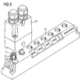
- FIG. 5 shows a connection side 13 of a module of an industrial automation system with a connection system according to an embodiment of the invention.
- the module is a peripheral module of an automation system, for example an input / output module, which is connected to a programmable logic controller via a serial fieldbus system such as Profibus DP.
- a serial fieldbus system such as Profibus DP.
- connection unit 14 is provided.
- This connection unit 14 is designed for further grinding of 16 A and comprises a 4 A branch in the form of a socket, which leads to the module to supply it with electricity.
- the module comprises a corresponding M12 connector 2.
- This connector 2 comprises a segment-wise interrupted external thread 3. About the thread, the connector 2 can be screwed with a conventional M12 socket to a tensile connection.
- connection unit 14 is designed for a pure plug connection.
- the integrated for contacting with the plug 2 socket is also formed with a segment-wise interrupted thread. This is an internal thread.
- the threaded portions of this internal thread can be passed through the interruptions 5 of the external thread 3, to connect socket and connector 2 without threaded engagement.
- the function of the thread remains for other connections.
Landscapes
- Details Of Connecting Devices For Male And Female Coupling (AREA)
Priority Applications (1)
| Application Number | Priority Date | Filing Date | Title |
|---|---|---|---|
| EP07013999A EP2017923A1 (fr) | 2007-07-17 | 2007-07-17 | Elément de liaison électrique |
Applications Claiming Priority (1)
| Application Number | Priority Date | Filing Date | Title |
|---|---|---|---|
| EP07013999A EP2017923A1 (fr) | 2007-07-17 | 2007-07-17 | Elément de liaison électrique |
Publications (1)
| Publication Number | Publication Date |
|---|---|
| EP2017923A1 true EP2017923A1 (fr) | 2009-01-21 |
Family
ID=38654606
Family Applications (1)
| Application Number | Title | Priority Date | Filing Date |
|---|---|---|---|
| EP07013999A Ceased EP2017923A1 (fr) | 2007-07-17 | 2007-07-17 | Elément de liaison électrique |
Country Status (1)
| Country | Link |
|---|---|
| EP (1) | EP2017923A1 (fr) |
Citations (4)
| Publication number | Priority date | Publication date | Assignee | Title |
|---|---|---|---|---|
| DE4441274C1 (de) * | 1994-11-19 | 1995-10-19 | Fraunhofer Ges Forschung | Sicherung für Steckverbindung |
| DE10121675A1 (de) * | 2000-05-09 | 2001-11-22 | Escha Bauelemente Gmbh | Elektrischer Steckverbinder |
| DE10301879B3 (de) * | 2003-01-17 | 2004-04-22 | Aloys Mennekes Anlagengesellschaft Mbh & Co. Kg | Steckvorrichtungselement mit Montagegewinde |
| EP1524732A1 (fr) * | 2003-10-18 | 2005-04-20 | Phoenix Contact GmbH & Co. KG | Connecteur électrique |
-
2007
- 2007-07-17 EP EP07013999A patent/EP2017923A1/fr not_active Ceased
Patent Citations (4)
| Publication number | Priority date | Publication date | Assignee | Title |
|---|---|---|---|---|
| DE4441274C1 (de) * | 1994-11-19 | 1995-10-19 | Fraunhofer Ges Forschung | Sicherung für Steckverbindung |
| DE10121675A1 (de) * | 2000-05-09 | 2001-11-22 | Escha Bauelemente Gmbh | Elektrischer Steckverbinder |
| DE10301879B3 (de) * | 2003-01-17 | 2004-04-22 | Aloys Mennekes Anlagengesellschaft Mbh & Co. Kg | Steckvorrichtungselement mit Montagegewinde |
| EP1524732A1 (fr) * | 2003-10-18 | 2005-04-20 | Phoenix Contact GmbH & Co. KG | Connecteur électrique |
Similar Documents
| Publication | Publication Date | Title |
|---|---|---|
| EP2208259B1 (fr) | Connecteur et raccord enfichable pour robot | |
| DE102015208400B4 (de) | Kabel-/Leitungseinführung | |
| EP2949013A1 (fr) | Connecteur coaxial équipé d'un écrou à baïonnette à éléments multiples | |
| EP2043202A1 (fr) | Connecteur à fiche électrique ou optique | |
| DE102015015202A1 (de) | Steckverbinder und Stecksystem | |
| EP3787128B1 (fr) | Connecteur enfichable | |
| DE102008046932A1 (de) | Gehäuse für eine elektrische Steckverbindung | |
| EP3358682A1 (fr) | Connecteur électrique à fiches et système de connecteur électrique à fiches | |
| DE102017200741B4 (de) | Rundsteckverbinder zur elektrischen Verbindung und mechanischen Verriegelung mit einem Standardgegenstück | |
| WO2021043525A1 (fr) | Dispositif de raccordement pour pilote de source lumineuse | |
| EP3123564B1 (fr) | Boîtier électronique avec un circuit imprimé et un composant électrique, et avec un dispositif de connexion électrique | |
| DE102005012441B4 (de) | Elektrischer Steckverbinder sowie Verfahren zur Herstellung eines elektrischen Steckverbinders | |
| WO2025237837A1 (fr) | Partie douille pour connexion de fiche électrique | |
| EP4496135A1 (fr) | Connecteur à enveloppe mobile | |
| BE1028592B1 (de) | Steckverbindersystem mit modularer Schnelltrennverbindung | |
| DE102016222862B4 (de) | Elektromechanische Steckverbindungseinrichtung und Verfahren zu ihrer Montage | |
| EP3143320A1 (fr) | Unité de raccordement destinée à un dispositif d'accouplement, en particulier à un raccord multiple | |
| WO2018153409A1 (fr) | Élément de raccordement | |
| EP3441997B1 (fr) | Dispositif de contacteur de sécurité permettant la sécurisation et/ou la mise sous tension d'au moins une machine électrique | |
| EP4378029A1 (fr) | Prise de courant | |
| EP3500075B1 (fr) | Module de communication pour un appareil de communication ou d'automatisation | |
| DE102020123487A1 (de) | Steckverbindersystem mit modularer Schnelltrennverbindung | |
| DE102022004518B3 (de) | Vorrichtung zum Herstellen einer elektrischen Verbindung zwischen einer Hochvolt-Leitung und einer Hochvolt-Komponente | |
| DE102019215630B4 (de) | Verbindungs-Struktur mit einem Solenoid-Ventil, einem Verbinder-Block und einem Hydraulik-Steuer-Mechanismus | |
| DE102025100687B3 (de) | Elektrischer Steckverbinder und Feldgerät |
Legal Events
| Date | Code | Title | Description |
|---|---|---|---|
| PUAI | Public reference made under article 153(3) epc to a published international application that has entered the european phase |
Free format text: ORIGINAL CODE: 0009012 |
|
| AK | Designated contracting states |
Kind code of ref document: A1 Designated state(s): AT BE BG CH CY CZ DE DK EE ES FI FR GB GR HU IE IS IT LI LT LU LV MC MT NL PL PT RO SE SI SK TR |
|
| AX | Request for extension of the european patent |
Extension state: AL BA HR MK RS |
|
| 17P | Request for examination filed |
Effective date: 20090706 |
|
| 17Q | First examination report despatched |
Effective date: 20090806 |
|
| AKX | Designation fees paid |
Designated state(s): DE FR GB IT |
|
| STAA | Information on the status of an ep patent application or granted ep patent |
Free format text: STATUS: THE APPLICATION HAS BEEN REFUSED |
|
| 18R | Application refused |
Effective date: 20091119 |