EP2017925B1 - USB-Standardschnittstellen-Verbindungen - Google Patents
USB-Standardschnittstellen-Verbindungen Download PDFInfo
- Publication number
- EP2017925B1 EP2017925B1 EP08156724A EP08156724A EP2017925B1 EP 2017925 B1 EP2017925 B1 EP 2017925B1 EP 08156724 A EP08156724 A EP 08156724A EP 08156724 A EP08156724 A EP 08156724A EP 2017925 B1 EP2017925 B1 EP 2017925B1
- Authority
- EP
- European Patent Office
- Prior art keywords
- mold
- assembly
- over
- shroud
- connector
- Prior art date
- Legal status (The legal status is an assumption and is not a legal conclusion. Google has not performed a legal analysis and makes no representation as to the accuracy of the status listed.)
- Active
Links
Images

Classifications
-
- H—ELECTRICITY
- H01—ELECTRIC ELEMENTS
- H01R—ELECTRICALLY-CONDUCTIVE CONNECTIONS; STRUCTURAL ASSOCIATIONS OF A PLURALITY OF MUTUALLY-INSULATED ELECTRICAL CONNECTING ELEMENTS; COUPLING DEVICES; CURRENT COLLECTORS
- H01R12/00—Structural associations of a plurality of mutually-insulated electrical connecting elements, specially adapted for printed circuits, e.g. printed circuit boards [PCB], flat or ribbon cables, or like generally planar structures, e.g. terminal strips, terminal blocks; Coupling devices specially adapted for printed circuits, flat or ribbon cables, or like generally planar structures; Terminals specially adapted for contact with, or insertion into, printed circuits, flat or ribbon cables, or like generally planar structures
- H01R12/50—Fixed connections
- H01R12/51—Fixed connections for rigid printed circuits or like structures
-
- H—ELECTRICITY
- H01—ELECTRIC ELEMENTS
- H01R—ELECTRICALLY-CONDUCTIVE CONNECTIONS; STRUCTURAL ASSOCIATIONS OF A PLURALITY OF MUTUALLY-INSULATED ELECTRICAL CONNECTING ELEMENTS; COUPLING DEVICES; CURRENT COLLECTORS
- H01R12/00—Structural associations of a plurality of mutually-insulated electrical connecting elements, specially adapted for printed circuits, e.g. printed circuit boards [PCB], flat or ribbon cables, or like generally planar structures, e.g. terminal strips, terminal blocks; Coupling devices specially adapted for printed circuits, flat or ribbon cables, or like generally planar structures; Terminals specially adapted for contact with, or insertion into, printed circuits, flat or ribbon cables, or like generally planar structures
- H01R12/70—Coupling devices
- H01R12/71—Coupling devices for rigid printing circuits or like structures
- H01R12/72—Coupling devices for rigid printing circuits or like structures coupling with the edge of the rigid printed circuits or like structures
- H01R12/721—Coupling devices for rigid printing circuits or like structures coupling with the edge of the rigid printed circuits or like structures cooperating directly with the edge of the rigid printed circuits
-
- H—ELECTRICITY
- H01—ELECTRIC ELEMENTS
- H01R—ELECTRICALLY-CONDUCTIVE CONNECTIONS; STRUCTURAL ASSOCIATIONS OF A PLURALITY OF MUTUALLY-INSULATED ELECTRICAL CONNECTING ELEMENTS; COUPLING DEVICES; CURRENT COLLECTORS
- H01R13/00—Details of coupling devices of the kinds covered by groups H01R12/70 or H01R24/00 - H01R33/00
- H01R13/64—Means for preventing incorrect coupling
-
- H—ELECTRICITY
- H01—ELECTRIC ELEMENTS
- H01R—ELECTRICALLY-CONDUCTIVE CONNECTIONS; STRUCTURAL ASSOCIATIONS OF A PLURALITY OF MUTUALLY-INSULATED ELECTRICAL CONNECTING ELEMENTS; COUPLING DEVICES; CURRENT COLLECTORS
- H01R13/00—Details of coupling devices of the kinds covered by groups H01R12/70 or H01R24/00 - H01R33/00
- H01R13/648—Protective earth or shield arrangements on coupling devices, e.g. anti-static shielding
- H01R13/658—High frequency shielding arrangements, e.g. against EMI [Electro-Magnetic Interference] or EMP [Electro-Magnetic Pulse]
- H01R13/6591—Specific features or arrangements of connection of shield to conductive members
- H01R13/6592—Specific features or arrangements of connection of shield to conductive members the conductive member being a shielded cable
-
- H—ELECTRICITY
- H01—ELECTRIC ELEMENTS
- H01R—ELECTRICALLY-CONDUCTIVE CONNECTIONS; STRUCTURAL ASSOCIATIONS OF A PLURALITY OF MUTUALLY-INSULATED ELECTRICAL CONNECTING ELEMENTS; COUPLING DEVICES; CURRENT COLLECTORS
- H01R13/00—Details of coupling devices of the kinds covered by groups H01R12/70 or H01R24/00 - H01R33/00
- H01R13/66—Structural association with built-in electrical component
- H01R13/719—Structural association with built-in electrical component specially adapted for high frequency, e.g. with filters
-
- H—ELECTRICITY
- H01—ELECTRIC ELEMENTS
- H01R—ELECTRICALLY-CONDUCTIVE CONNECTIONS; STRUCTURAL ASSOCIATIONS OF A PLURALITY OF MUTUALLY-INSULATED ELECTRICAL CONNECTING ELEMENTS; COUPLING DEVICES; CURRENT COLLECTORS
- H01R13/00—Details of coupling devices of the kinds covered by groups H01R12/70 or H01R24/00 - H01R33/00
- H01R13/648—Protective earth or shield arrangements on coupling devices, e.g. anti-static shielding
- H01R13/658—High frequency shielding arrangements, e.g. against EMI [Electro-Magnetic Interference] or EMP [Electro-Magnetic Pulse]
- H01R13/6591—Specific features or arrangements of connection of shield to conductive members
- H01R13/6594—Specific features or arrangements of connection of shield to conductive members the shield being mounted on a PCB and connected to conductive members
Definitions
- the present invention is directed towards an assembly adaptation device, and, more specifically, to a USB interface connector for aiding connectivity between a consumer's device and to an electrical interface of a machine or other system.
- USB Universal Serial Bus
- RCA inputs RCA inputs
- jacks RCA inputs
- USB Mini-B adaptors are common interface types in the consumer industry, but not to other industrial applications.
- USB standard interface connections as defined and used under the USB published standards provide acceptable features as applied to their use in traditional consumer electronics by the general public. Taking the interface detail standards and packaging them with the intent of creating a connection package compatible with the know build and use environment of an industrial assembly plant (IAP) requires providing much improved physical robustness and added mate indexing control above and beyond what the existing accepted USB configurations can provide.
- IAP build compatibility requires yet additional features to meet increases in mated retention force and miss-plug resistance force as defined in SAE/USCAR-30 specific to USB. These added features will by definition interact with device details incorporated as mating standards by SAE/USCAR-30.
- USB adapter can disengage from its female counterpart, which is undesirable.
- a consumer device interface assembly having a female shroud with a housing and a flange for mounting to a pc board.
- the housing has an indexing feature, a ramp integral with the housing, and a pair of slots.
- the assembly includes an over-mold configured to be received within the female shroud, the over-mold having a body with a pair of arms that fit within the pair of slots of the female shroud, the body further having a tab.
- a connector located within the over-mold includes a cable and a body.
- the assembly further includes a metal lock shell configured to receive the over-mold, the shell having protrusions that receive the arms of the over-mold, an interlocking tab portion mates with the ramp of the female shroud for securing the assembly together , wherein the slots of the housing are positioned on each side of the ramp, exterd upwardly and axially, and have an open side; the arms of the body exterd upwardly and axially and are received through the open sides to be positioned within the pair of slots; and wherein the interlocking tab portion mates with the ramp between the pair of arms.
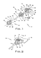
- FIG. 1 is an exploded assembly of a male interface and its associated female receptacle shroud, according to an embodiment
- FIG. 2 is the FIG. 1 assembly shown in its connected position and with the shroud assembly secured to a PC board, according to an embodiment
- FIG. 3 is a side elevational view taken from Section 3-3 of FIG. 2 , illustrating a USB male adapter positioned within the female USB shroud, according to an embodiment
- FIG. 4 is a perspective view of an alternative embodiment USB mini-receptacle assembly having an integral locking clip with its over-mold, according to an embodiment
- FIG. 5 is a perspective view of the FIG. 4 embodiment, showing the USB cable having a body, with the locking clip offset there from, the over-mold not being illustrated in this simplified view, according to an embodiment;
- FIG. 6 is a section cut taken from line 6-6 of FIG. 4 , illustrating the integral locking clip and the connecter relative to the over-mold, according to an embodiment.
- a consumer device interface assembly having a connector, a locking clip, and an over-mold.
- the connector has a body and a consumer interface extending from the body.
- the locking clip is secured to the connector and prevents disassembly from its corresponding component to which it engages.
- the over-mold surrounds the body of the connector and provides a physically robust component to be received by a corresponding interface component.
- a consumer device interface assembly 10 is illustrated having a USB Mini-B receptacle connector 12, an over-mold 14, and a lock shell 16.
- the over-mold 14 includes a cable assembly 18 and a body 20 integral with one another. It will be appreciated that the receptacle 12 does not have to be of the USB type illustrated, but of any variety of female connector system so as to provide connectivity to a PC board.
- the cable assembly 18 has a cable 22, a wire strain relief 24, a connector 25 with a shell 26 made of plastic, and a consumer device interface 28 (See FIG. 5 ).
- the consumer device interface 28 illustrated is a USB Mini-B male connector that mates with a corresponding female connector 30 that is housed within the USB Mini-B receptacle 12. It will be appreciated that the consumer device interface 28 could be with any consumer interface device configuration, including, but not limited to, USB Mini-B, USB standard, and 3.5 millimeter audio/visual plugs.
- the over-mold 14 is universal in that it is capable of receiving cable or connector assemblies 18 of various types, yet still be allowed to mate with a standard receptacle 12.
- the receptacle 12 can be of configurations besides the USB Mini-B receptacle as shown.
- the female connector 30 can be of any configuration such as a USB Standard, or A/V jacks, or any other female connector configuration, so as to allow it to mate with its corresponding male interface component 28.
- the universal male over-mold connector 14 has a body 20 with a pair of upwardly extending arms 32 that extend axially and are spaced apart from one another.
- a flattened portion 34 is recessed below the upper part of the arms 32 and provides a cavity for receiving a portion of the lock shell 16.
- a tab 36 is formed part of, and in one embodiment, positioned about a rear corner of the body 20 and is operable to engage an opening 38 of the lock shell 16. This allows the over-mold 14 and the lock shell 16 to securely engage one another.
- the universal over-mold 14 has on one corner of its body 20, a self-indexing feature 40 including a chamfer 42 and an axially extending relief or corner 44.
- This self-indexing feature 40 corresponds with a corresponding configuration of the receptacle 12 shown in FIG. 1 .
- the receptacle 12 has a chamfer 46 and a lip 48 that engaged the corresponding configuration molded within the male over-mold 14.
- the over-mold is preferably made of plastic. This arrangement enhances quick and accurate assembly of the parts.
- a housing 50 is provided with a corresponding PC board mounting member for flange 52.
- the receptacle 12 is preferable made of plastic and is secured to a PC board 54 (See FIG. 2 ) by conventional means.
- the housing 50 has vertical side walls 56, a base 58, the indexing feature 60 and an upper portion 62.
- the female connector 30 is positioned within the receptacle 12 and is secured to the PC board 54, via traditional methods.
- the upper portion 62 has a pair of slots 64 extending axially and are operable to receive the arms 32 from the over-mold male counterpart 14.
- the male over-mold 14 is configured to be slidably received within the cavity 66 that is defined by the aforementioned housing components 50.
- a ramp 68 is provided on the upper portion 62 within a recessed area 70.
- the ramp 68 is for engaging the interlocking tab 72 that is part of the lock shell 16.
- the interlocking tab 72 has an opening 74 that is sufficiently large to receive the entirety of the ramp 68 which, when engaged, causes the lock shell 16 and the receptacle 12, to be temporarily secured firmly together.
- the interlocking tab 72 further includes a raised portion 76 that engages the ramp 68, and a pair of upwardly extending flanges 78 that are received within the recessed area 70 and glide along upwardly extending walls 80. This configuration provides additional indexing control as well as a positive engagement between the receptacle 12 and the lock shell 16.
- the lock shell 16 further includes upwardly extending arms 82 that are configured to be received over the ramp portion 84 of the over-mold body 20.
- a shroud 86 extends around the wire strain relief 24.
- a ramp 88 is positioned on one or both sides of the lock shell 16 and are operable to receive the tab 36 of the over-mold 14. Opening 38 is sufficiently enlarged to receive tab 36 allowing the forward edge of tab 36 to engage the rear wall of the ramp 88.
- the interface assembly 10 is illustrated having the receptacle 12 and the male over-mold 14 with its lock shell 16, engaged in a locking arrangement.
- the interlocking tab 72 is shown engaged with the ramp 68 thus securely engaging the components together. This arrangement provides a firm connection about the componentry.
- this side elevational sectional view illustrates the male over-mold connector 14 engaged within the receptacle 12. While a USB Mini-B receptacle configuration is illustrated, it will be appreciated that other interface adapter configurations are contemplated by the present invention.
- the interlocking tab 72 is shown engaging the ramp 62 thus securely engaging the components to one another. If a consumer wants to disengage and release the male over-mold connector portion 14 from the receptacle 12, the raised portion 76 can be lifted up thus allowing the opening 74 to disengage from the ramp 62. The components are now freed, and can then be disassembled.
- an alternative embodiment assembly 90 is illustrated having many of the same components as that illustrated in FIG. 1 .
- the alternative assembly 90 has an integral locking clip 92 that is integrally molded with the over-mold 14.
- the locking clip 92 is used in lieu thereof.
- the locking clip 92 has a connector portion 94 with a pair of downwardly extending arms that engage a corresponding conically shaped portion 98 of the shell 26.
- the locking clip 92 further has an interlocking tab portion 100 with its own ramp 102 and opening 104.
- the locking clip 92 can be made of variety of materials, including metal and plastic.
- the locking clip could preferably be made of metal which in turn engages a metal shroud 106 that is positioned around the perimeter of the shell 26, for enhancing grounding and filtering effects.
- the metal shroud 106 acts as a filter and protects the shell 26 from external noise so as to enhance clear signal input to the receptacle 12.
- the shell 26 of the connector 25 is made of plastic and is provided with a Mini-B device interface 28, and the locking clip 92 is positioned downwardly and secured thereto when the arms 96 engage the contour 98.
- the part is then ready for an over-mold for the body 20 material to be injected or applied through some other means, and introduced around the shell 26 and locking clip 92.
- This provides for a locking clip portion 108 to extend outside of the body 20 of the over-mold resulting in a robust unitary component.
- the locking clip 92 is rigidly secured and a part of the over-mold body 20 now having its associated consumer interface 28 and cable 22 extending there from.
- the assembly is now ready for insertion within a receptacle 12.
- FIG. 6 illustrates a side elevational sectional cut view taken along lines 6-6 of the FIG. 4 alternative embodiment.
- the locking clip 92 is shown integrally molded or otherwise positioned within the body 20 of the over-mold.
- the locking clip portion 108 is now unitary thus creating a strong, robust assembly for use in a VAP.
- a wire 104 is shown extending thru the shell 26 and connects the interface 28 to the cable 22.
Landscapes
- Details Of Connecting Devices For Male And Female Coupling (AREA)
- Coupling Device And Connection With Printed Circuit (AREA)
Claims (13)
- Schnittstellenbaugruppe für eine Konsumentenvorrichtung (10), die aufweist:eine weibliche Hülle (12) mit einem Gehäuse (50) und einer Flansch (52) zum Anbringen an einer Leiterplatte, wobei das Gehäuse ein Indizierungsmerkmal (60) und eine Rampe (68) integral mit dem Gehäuse hat, wobei das Gehäuse weiter ein Paar von Schlitzen (64) hat;eine Umspritzung (14), die konfiguriert ist, in der weiblichen Hülle aufgenommen zu werden, wobei die Umspritzung einen Körper (20) mit einem Paar von Armen (32) hat, die in das Paar von Schlitzen der weiblichen Hülle passen, wobei der Körper weiter einen Tab (36) hat;einen Verbinder (25), der sich in der Umspritzung befindet, wobei der Verbinder eine Leitung (32) und einen Körper (26) hat; undeine Metallverriegelungshülle (16), die konfiguriert ist zur Aufnahme der Umspritzung, wobei die Hülle Vorsprünge hat, die die Arme der Umspritzung aufnehmen, wobei ein Verriegelungs-Tabteil (72) mit der Rampe der weiblichen Hülle verbunden ist zum sicheren Verbinden der Baugruppe; dadurch gekennzeichnet, dassdie Schlitze (64) des Gehäuses (50) an jeder Seite der Rampe (68) positioniert sind, sich nach oben und axial erstrecken und eine offene Seite haben; dassdie Arme (32) des Körpers (20) sich nach oben und axial erstrecken und durch die offenen Seiten aufgenommen werden, um in dem Paar von Schlitzen (64) positioniert zu werden; und dadurch dassdas Verriegelungs-Tabteil (72) mit der Rampe (68) zwischen den Paaren von Armen (32) verbunden wird.
- Baugruppe gemäß Anspruch 1, wobei die Metallverriegelungshülle (16) und die Umspritzung (14) integral sind.
- Baugruppe gemäß Anspruch 1, wobei die Metallverriegelungshülle (16) aus leitendem Material besteht.
- Baugruppe gemäß Anspruch 1, wobei der Körper des Verbinders (25) eine dünne Metallumhüllung (106) hat, die aus leitendem Material besteht.
- Baugruppe gemäß Anspruch 1, wobei die Metallverriegelungshülle (16) weiter eine Öffnung (38) hat, die betriebsfähig ist zur Aufnahme des Tabteils (36) an dem Körper (20) der Umspritzung (14), um so die Umspritzung und die Hülle miteinander zu verriegeln.
- Baugruppe gemäß Anspruch 1, wobei die Metallverriegelungshülle (16) weiter eine Hülse (86) hat, die die Leitung umgibt.
- Baugruppe gemäß Anspruch 1, wobei der Verbinder (25) zumindest einer der folgenden Typen ist:a) USB-Schnittstelle;b) RCA-Eingang;c) Hilfseingang;f) Buchse oder Anschluss.
- Baugruppe gemäß Anspruch 1, wobei das Indizierungsmerkmal (60) der weiblichen Hülle eine Abkantung (46) an einer Ecke des Gehäuses (50) der Hülle umfasst, wobei die Abkantung mit einer entsprechenden Abkantung (42) des Körpers der Umspritzung (14) zusammenpasst.
- Baugruppe gemäß Anspruch 1, wobei das Indizierungsmerkmal (60) der weiblichen Hülle eine Lippe (48) an einer inneren Oberfläche des Gehäuses umfasst.
- Baugruppe gemäß Anspruch 9, wobei der Körper (20) der Umspritzung (14) ein rechtwinklig geformtes Eck (44) umfasst, das mit der Lippe in Eingriff ist, um die Hülle und die Umspritzung auszurichten.
- Baugruppe gemäß Anspruch 1, wobei der Körper (26) des Verbinders (25) in der Umspritzung ausgeformt ist.
- Baugruppe gemäß Anspruch 1, wobei die Metallverriegelungshülle (16) und die weibliche Hülle (86) einen leitenden Pfad zu einer Leiterplatte bilden.
- Baugruppe gemäß Anspruch 1, wobei der Verbinder (25) eine USB-Mini-Konfiguration hat.
Applications Claiming Priority (1)
| Application Number | Priority Date | Filing Date | Title |
|---|---|---|---|
| US11/811,900 US7753713B2 (en) | 2007-06-12 | 2007-06-12 | Universal serial bus standard interface connections |
Publications (2)
| Publication Number | Publication Date |
|---|---|
| EP2017925A1 EP2017925A1 (de) | 2009-01-21 |
| EP2017925B1 true EP2017925B1 (de) | 2012-02-22 |
Family
ID=39901735
Family Applications (1)
| Application Number | Title | Priority Date | Filing Date |
|---|---|---|---|
| EP08156724A Active EP2017925B1 (de) | 2007-06-12 | 2008-05-22 | USB-Standardschnittstellen-Verbindungen |
Country Status (5)
| Country | Link |
|---|---|
| US (1) | US7753713B2 (de) |
| EP (1) | EP2017925B1 (de) |
| JP (1) | JP2008311228A (de) |
| KR (1) | KR101495912B1 (de) |
| AT (1) | ATE546863T1 (de) |
Families Citing this family (14)
| Publication number | Priority date | Publication date | Assignee | Title |
|---|---|---|---|---|
| US7751907B2 (en) | 2007-05-24 | 2010-07-06 | Smiths Medical Asd, Inc. | Expert system for insulin pump therapy |
| US8766476B2 (en) | 2009-10-02 | 2014-07-01 | Ramin Rostami | Apparatus and method for communicating data and power with electronic devices |
| US8487476B2 (en) * | 2009-03-09 | 2013-07-16 | Ramin Rostami | Apparatus and methods for powering mobile devices |
| US9118194B2 (en) | 2012-04-30 | 2015-08-25 | Foreign Trade Corporation | Configurable apparatus and methods for supplying power and data to electronic devices |
| JP2013510403A (ja) | 2009-11-03 | 2013-03-21 | ベル フューズ (マカオ コマーシャル オフショア) リミテッド | 高速用モジュラーコネクタプラグ |
| US9715607B2 (en) | 2010-02-11 | 2017-07-25 | Advanced Wireless Innovations Llc | Apparatus and methods for communicating power and data with electronic devices |
| CN102544907A (zh) * | 2010-12-09 | 2012-07-04 | 鸿富锦精密工业(深圳)有限公司 | Usb插件固定机构 |
| US9994378B2 (en) | 2011-08-15 | 2018-06-12 | Graham Packaging Company, L.P. | Plastic containers, base configurations for plastic containers, and systems, methods, and base molds thereof |
| US9381297B2 (en) * | 2012-06-07 | 2016-07-05 | Tandem Diabetes Care, Inc. | Sealed infusion device with electrical connector port |
| US9438051B2 (en) * | 2013-05-03 | 2016-09-06 | Casco Products Corporation | USB power outlet/charger direct replacement for automotive cigar lighter/power outlet |
| US9960621B2 (en) | 2015-03-12 | 2018-05-01 | Streamlight, Inc. | USB connector usable with a battery charger and otherwise |
| WO2016145194A1 (en) * | 2015-03-12 | 2016-09-15 | Streamlight, Inc. | Battery charger usable with plural different power supplies and usb connector usable therewith and otherwise |
| JP2019140046A (ja) * | 2018-02-15 | 2019-08-22 | 住友電装株式会社 | コネクタ、コネクタ装置 |
| EP4396909A4 (de) | 2021-09-01 | 2025-10-15 | Fci Usa Llc | Robuster verbinder für hohe geschwindigkeiten |
Family Cites Families (20)
| Publication number | Priority date | Publication date | Assignee | Title |
|---|---|---|---|---|
| JPS63152818A (ja) * | 1986-12-17 | 1988-06-25 | 多摩電気工業株式会社 | シ−ルド付ケ−ブル・コネクタ一体型ケ−ブル |
| US5480327A (en) * | 1994-05-24 | 1996-01-02 | The Whitaker Corporation | Electrical connector for cable |
| US5486117A (en) * | 1994-08-09 | 1996-01-23 | Molex Incorporated | Locking system for an electrical connector assembly |
| US6116938A (en) * | 1997-08-28 | 2000-09-12 | The Whitaker Corporation | Low profile electrical connector |
| US6328601B1 (en) * | 1998-01-15 | 2001-12-11 | The Siemon Company | Enhanced performance telecommunications connector |
| JP2000223218A (ja) * | 1999-01-27 | 2000-08-11 | Mitsumi Electric Co Ltd | 小型コネクタ |
| JP3724703B2 (ja) * | 2000-06-05 | 2005-12-07 | 矢崎総業株式会社 | 半嵌合防止コネクタ |
| US6394824B1 (en) * | 2001-04-04 | 2002-05-28 | Hon Hai Precision Ind. Co., Ltd. | Electrical connector |
| US6398576B1 (en) * | 2001-04-13 | 2002-06-04 | Hon Hai Precision Ind. Co. Ltd. | Electrical connector having bracket-covered latch |
| JP2003243093A (ja) * | 2002-02-21 | 2003-08-29 | Yazaki Corp | Usbコネクタ |
| US6619989B1 (en) * | 2002-05-30 | 2003-09-16 | Hon Hai Precision Ind. Co., Ltd. | Cable connector having integrally formed metal latch and cable strain relief |
| US6585537B1 (en) * | 2002-10-24 | 2003-07-01 | Hon Hai Precision Ind. Co., Ltd. | Cable end connector with locking member |
| US6830472B1 (en) * | 2003-09-10 | 2004-12-14 | Hon Hai Precision Ind. Co., Ltd. | Cable end connector assembly having locking member |
| TWM257029U (en) * | 2004-04-30 | 2005-02-11 | Advanced Connectek Inc | Electrical connector with a locking device |
| TWM261868U (en) * | 2004-06-18 | 2005-04-11 | Advanced Connectek Inc | An electrical connector with a latch device |
| JP2006222027A (ja) * | 2005-02-14 | 2006-08-24 | Sumitomo Wiring Syst Ltd | シールドコネクタ |
| US7285004B1 (en) * | 2005-04-21 | 2007-10-23 | Yazaki North America, Inc. | USB locking connector system |
| JP4266372B2 (ja) * | 2005-06-01 | 2009-05-20 | 日本航空電子工業株式会社 | コネクタ |
| JP4360364B2 (ja) * | 2005-08-26 | 2009-11-11 | パナソニック電工株式会社 | コネクタ |
| JP4127705B2 (ja) * | 2005-10-07 | 2008-07-30 | 日本航空電子工業株式会社 | 電気コネクタ |
-
2007
- 2007-06-12 US US11/811,900 patent/US7753713B2/en active Active
-
2008
- 2008-05-22 AT AT08156724T patent/ATE546863T1/de active
- 2008-05-22 EP EP08156724A patent/EP2017925B1/de active Active
- 2008-06-06 JP JP2008148854A patent/JP2008311228A/ja active Pending
- 2008-06-11 KR KR20080054443A patent/KR101495912B1/ko active Active
Also Published As
| Publication number | Publication date |
|---|---|
| US20080311791A1 (en) | 2008-12-18 |
| US7753713B2 (en) | 2010-07-13 |
| EP2017925A1 (de) | 2009-01-21 |
| ATE546863T1 (de) | 2012-03-15 |
| JP2008311228A (ja) | 2008-12-25 |
| KR101495912B1 (ko) | 2015-02-25 |
| KR20080109633A (ko) | 2008-12-17 |
Similar Documents
| Publication | Publication Date | Title |
|---|---|---|
| EP2017925B1 (de) | USB-Standardschnittstellen-Verbindungen | |
| US8282411B2 (en) | Connector position assurance lock | |
| CN102074838B (zh) | 具有锁圈的电连接器 | |
| CN104362450B (zh) | 具有双向插接功能的插头连接器 | |
| US7815460B2 (en) | Connector with an anti-loose fastening device | |
| JP7676370B2 (ja) | 電気的プラグコネクタ及びこの種のプラグコネクタ用のシール | |
| EP0827239A2 (de) | Buchse mit integriertem Detektor | |
| US20130203299A1 (en) | Contact Housing For Electrical Contact Units, Electrical Plug Connector or Mating Connector as Well as an Assembled Electrical Conductor | |
| EP1764877B1 (de) | Verbinder , Gegenstück und Verbindungsanordnung | |
| EP2510592B1 (de) | Verbinderbaugruppe | |
| CN105009378A (zh) | 连接器配合保证 | |
| US9831577B2 (en) | Board connector | |
| US6773293B1 (en) | Cable end connector with locking member | |
| EP2955797A1 (de) | Kabelzugentlastung | |
| CN110336153A (zh) | 连接器及防水连接器 | |
| US10992090B2 (en) | Cable connector assembly having two plugs for providing a secure connection | |
| US5151048A (en) | Failsafe electrical connector | |
| CN205828772U (zh) | 模块用连接器 | |
| US20060154524A1 (en) | Shell for electrical connector | |
| CN204179286U (zh) | 具有双向插接功能的插头连接器 | |
| US7419399B2 (en) | Panel mount connector with integrated latch and polarizing key | |
| CN100511859C (zh) | 具有改进的锁定装置的杠杆式电连接器组件 | |
| CN205488908U (zh) | 多功能双面连接器 | |
| CN201207537Y (zh) | 电连接器 | |
| CN111403927B (zh) | 连接器组合体 |
Legal Events
| Date | Code | Title | Description |
|---|---|---|---|
| PUAI | Public reference made under article 153(3) epc to a published international application that has entered the european phase |
Free format text: ORIGINAL CODE: 0009012 |
|
| PUAI | Public reference made under article 153(3) epc to a published international application that has entered the european phase |
Free format text: ORIGINAL CODE: 0009012 |
|
| AK | Designated contracting states |
Kind code of ref document: A1 Designated state(s): AT BE BG CH CY CZ DE DK EE ES FI FR GB GR HR HU IE IS IT LI LT LU LV MC MT NL NO PL PT RO SE SI SK TR |
|
| AX | Request for extension of the european patent |
Extension state: AL BA MK RS |
|
| 17P | Request for examination filed |
Effective date: 20090721 |
|
| 17Q | First examination report despatched |
Effective date: 20090814 |
|
| AKX | Designation fees paid |
Designated state(s): AT BE BG CH CY CZ DE DK EE ES FI FR GB GR HR HU IE IS IT LI LT LU LV MC MT NL NO PL PT RO SE SI SK TR |
|
| GRAP | Despatch of communication of intention to grant a patent |
Free format text: ORIGINAL CODE: EPIDOSNIGR1 |
|
| RIC1 | Information provided on ipc code assigned before grant |
Ipc: H01R 13/64 20060101AFI20110825BHEP Ipc: H01R 13/719 20110101ALI20110825BHEP Ipc: H01R 12/71 20110101ALI20110825BHEP Ipc: H01R 13/658 20110101ALI20110825BHEP Ipc: H01R 12/72 20110101ALI20110825BHEP |
|
| GRAS | Grant fee paid |
Free format text: ORIGINAL CODE: EPIDOSNIGR3 |
|
| GRAA | (expected) grant |
Free format text: ORIGINAL CODE: 0009210 |
|
| AK | Designated contracting states |
Kind code of ref document: B1 Designated state(s): AT BE BG CH CY CZ DE DK EE ES FI FR GB GR HR HU IE IS IT LI LT LU LV MC MT NL NO PL PT RO SE SI SK TR |
|
| REG | Reference to a national code |
Ref country code: GB Ref legal event code: FG4D |
|
| REG | Reference to a national code |
Ref country code: CH Ref legal event code: EP |
|
| REG | Reference to a national code |
Ref country code: AT Ref legal event code: REF Ref document number: 546863 Country of ref document: AT Kind code of ref document: T Effective date: 20120315 |
|
| REG | Reference to a national code |
Ref country code: IE Ref legal event code: FG4D |
|
| REG | Reference to a national code |
Ref country code: DE Ref legal event code: R096 Ref document number: 602008013537 Country of ref document: DE Effective date: 20120419 |
|
| REG | Reference to a national code |
Ref country code: NL Ref legal event code: VDEP Effective date: 20120222 |
|
| LTIE | Lt: invalidation of european patent or patent extension |
Effective date: 20120222 |
|
| PG25 | Lapsed in a contracting state [announced via postgrant information from national office to epo] |
Ref country code: NO Free format text: LAPSE BECAUSE OF FAILURE TO SUBMIT A TRANSLATION OF THE DESCRIPTION OR TO PAY THE FEE WITHIN THE PRESCRIBED TIME-LIMIT Effective date: 20120522 Ref country code: NL Free format text: LAPSE BECAUSE OF FAILURE TO SUBMIT A TRANSLATION OF THE DESCRIPTION OR TO PAY THE FEE WITHIN THE PRESCRIBED TIME-LIMIT Effective date: 20120222 Ref country code: LT Free format text: LAPSE BECAUSE OF FAILURE TO SUBMIT A TRANSLATION OF THE DESCRIPTION OR TO PAY THE FEE WITHIN THE PRESCRIBED TIME-LIMIT Effective date: 20120222 Ref country code: HR Free format text: LAPSE BECAUSE OF FAILURE TO SUBMIT A TRANSLATION OF THE DESCRIPTION OR TO PAY THE FEE WITHIN THE PRESCRIBED TIME-LIMIT Effective date: 20120222 Ref country code: IS Free format text: LAPSE BECAUSE OF FAILURE TO SUBMIT A TRANSLATION OF THE DESCRIPTION OR TO PAY THE FEE WITHIN THE PRESCRIBED TIME-LIMIT Effective date: 20120622 |
|
| PG25 | Lapsed in a contracting state [announced via postgrant information from national office to epo] |
Ref country code: BE Free format text: LAPSE BECAUSE OF FAILURE TO SUBMIT A TRANSLATION OF THE DESCRIPTION OR TO PAY THE FEE WITHIN THE PRESCRIBED TIME-LIMIT Effective date: 20120222 Ref country code: GR Free format text: LAPSE BECAUSE OF FAILURE TO SUBMIT A TRANSLATION OF THE DESCRIPTION OR TO PAY THE FEE WITHIN THE PRESCRIBED TIME-LIMIT Effective date: 20120523 Ref country code: PT Free format text: LAPSE BECAUSE OF FAILURE TO SUBMIT A TRANSLATION OF THE DESCRIPTION OR TO PAY THE FEE WITHIN THE PRESCRIBED TIME-LIMIT Effective date: 20120622 Ref country code: LV Free format text: LAPSE BECAUSE OF FAILURE TO SUBMIT A TRANSLATION OF THE DESCRIPTION OR TO PAY THE FEE WITHIN THE PRESCRIBED TIME-LIMIT Effective date: 20120222 Ref country code: FI Free format text: LAPSE BECAUSE OF FAILURE TO SUBMIT A TRANSLATION OF THE DESCRIPTION OR TO PAY THE FEE WITHIN THE PRESCRIBED TIME-LIMIT Effective date: 20120222 |
|
| REG | Reference to a national code |
Ref country code: AT Ref legal event code: MK05 Ref document number: 546863 Country of ref document: AT Kind code of ref document: T Effective date: 20120222 |
|
| PG25 | Lapsed in a contracting state [announced via postgrant information from national office to epo] |
Ref country code: CY Free format text: LAPSE BECAUSE OF FAILURE TO SUBMIT A TRANSLATION OF THE DESCRIPTION OR TO PAY THE FEE WITHIN THE PRESCRIBED TIME-LIMIT Effective date: 20120222 |
|
| PG25 | Lapsed in a contracting state [announced via postgrant information from national office to epo] |
Ref country code: EE Free format text: LAPSE BECAUSE OF FAILURE TO SUBMIT A TRANSLATION OF THE DESCRIPTION OR TO PAY THE FEE WITHIN THE PRESCRIBED TIME-LIMIT Effective date: 20120222 Ref country code: SI Free format text: LAPSE BECAUSE OF FAILURE TO SUBMIT A TRANSLATION OF THE DESCRIPTION OR TO PAY THE FEE WITHIN THE PRESCRIBED TIME-LIMIT Effective date: 20120222 Ref country code: CZ Free format text: LAPSE BECAUSE OF FAILURE TO SUBMIT A TRANSLATION OF THE DESCRIPTION OR TO PAY THE FEE WITHIN THE PRESCRIBED TIME-LIMIT Effective date: 20120222 Ref country code: SE Free format text: LAPSE BECAUSE OF FAILURE TO SUBMIT A TRANSLATION OF THE DESCRIPTION OR TO PAY THE FEE WITHIN THE PRESCRIBED TIME-LIMIT Effective date: 20120222 Ref country code: PL Free format text: LAPSE BECAUSE OF FAILURE TO SUBMIT A TRANSLATION OF THE DESCRIPTION OR TO PAY THE FEE WITHIN THE PRESCRIBED TIME-LIMIT Effective date: 20120222 Ref country code: RO Free format text: LAPSE BECAUSE OF FAILURE TO SUBMIT A TRANSLATION OF THE DESCRIPTION OR TO PAY THE FEE WITHIN THE PRESCRIBED TIME-LIMIT Effective date: 20120222 Ref country code: DK Free format text: LAPSE BECAUSE OF FAILURE TO SUBMIT A TRANSLATION OF THE DESCRIPTION OR TO PAY THE FEE WITHIN THE PRESCRIBED TIME-LIMIT Effective date: 20120222 |
|
| PG25 | Lapsed in a contracting state [announced via postgrant information from national office to epo] |
Ref country code: IT Free format text: LAPSE BECAUSE OF FAILURE TO SUBMIT A TRANSLATION OF THE DESCRIPTION OR TO PAY THE FEE WITHIN THE PRESCRIBED TIME-LIMIT Effective date: 20120222 Ref country code: SK Free format text: LAPSE BECAUSE OF FAILURE TO SUBMIT A TRANSLATION OF THE DESCRIPTION OR TO PAY THE FEE WITHIN THE PRESCRIBED TIME-LIMIT Effective date: 20120222 |
|
| PLBE | No opposition filed within time limit |
Free format text: ORIGINAL CODE: 0009261 |
|
| STAA | Information on the status of an ep patent application or granted ep patent |
Free format text: STATUS: NO OPPOSITION FILED WITHIN TIME LIMIT |
|
| PG25 | Lapsed in a contracting state [announced via postgrant information from national office to epo] |
Ref country code: MC Free format text: LAPSE BECAUSE OF NON-PAYMENT OF DUE FEES Effective date: 20120531 |
|
| REG | Reference to a national code |
Ref country code: CH Ref legal event code: PL |
|
| 26N | No opposition filed |
Effective date: 20121123 |
|
| PG25 | Lapsed in a contracting state [announced via postgrant information from national office to epo] |
Ref country code: AT Free format text: LAPSE BECAUSE OF FAILURE TO SUBMIT A TRANSLATION OF THE DESCRIPTION OR TO PAY THE FEE WITHIN THE PRESCRIBED TIME-LIMIT Effective date: 20120222 Ref country code: LI Free format text: LAPSE BECAUSE OF NON-PAYMENT OF DUE FEES Effective date: 20120531 Ref country code: CH Free format text: LAPSE BECAUSE OF NON-PAYMENT OF DUE FEES Effective date: 20120531 |
|
| REG | Reference to a national code |
Ref country code: IE Ref legal event code: MM4A |
|
| REG | Reference to a national code |
Ref country code: DE Ref legal event code: R097 Ref document number: 602008013537 Country of ref document: DE Effective date: 20121123 |
|
| PG25 | Lapsed in a contracting state [announced via postgrant information from national office to epo] |
Ref country code: ES Free format text: LAPSE BECAUSE OF FAILURE TO SUBMIT A TRANSLATION OF THE DESCRIPTION OR TO PAY THE FEE WITHIN THE PRESCRIBED TIME-LIMIT Effective date: 20120602 Ref country code: IE Free format text: LAPSE BECAUSE OF NON-PAYMENT OF DUE FEES Effective date: 20120522 |
|
| PG25 | Lapsed in a contracting state [announced via postgrant information from national office to epo] |
Ref country code: MT Free format text: LAPSE BECAUSE OF FAILURE TO SUBMIT A TRANSLATION OF THE DESCRIPTION OR TO PAY THE FEE WITHIN THE PRESCRIBED TIME-LIMIT Effective date: 20120222 Ref country code: BG Free format text: LAPSE BECAUSE OF FAILURE TO SUBMIT A TRANSLATION OF THE DESCRIPTION OR TO PAY THE FEE WITHIN THE PRESCRIBED TIME-LIMIT Effective date: 20120522 |
|
| PG25 | Lapsed in a contracting state [announced via postgrant information from national office to epo] |
Ref country code: TR Free format text: LAPSE BECAUSE OF FAILURE TO SUBMIT A TRANSLATION OF THE DESCRIPTION OR TO PAY THE FEE WITHIN THE PRESCRIBED TIME-LIMIT Effective date: 20120222 |
|
| PG25 | Lapsed in a contracting state [announced via postgrant information from national office to epo] |
Ref country code: LU Free format text: LAPSE BECAUSE OF NON-PAYMENT OF DUE FEES Effective date: 20120522 |
|
| PG25 | Lapsed in a contracting state [announced via postgrant information from national office to epo] |
Ref country code: HU Free format text: LAPSE BECAUSE OF FAILURE TO SUBMIT A TRANSLATION OF THE DESCRIPTION OR TO PAY THE FEE WITHIN THE PRESCRIBED TIME-LIMIT Effective date: 20080522 |
|
| REG | Reference to a national code |
Ref country code: FR Ref legal event code: PLFP Year of fee payment: 9 |
|
| REG | Reference to a national code |
Ref country code: FR Ref legal event code: PLFP Year of fee payment: 10 |
|
| REG | Reference to a national code |
Ref country code: FR Ref legal event code: PLFP Year of fee payment: 11 |
|
| REG | Reference to a national code |
Ref country code: DE Ref legal event code: R081 Ref document number: 602008013537 Country of ref document: DE Owner name: APTIV TECHNOLOGIES LIMITED, BB Free format text: FORMER OWNER: DELPHI TECHNOLOGIES, INC., TROY, MICH., US |
|
| REG | Reference to a national code |
Ref country code: GB Ref legal event code: 732E Free format text: REGISTERED BETWEEN 20190117 AND 20190123 |
|
| REG | Reference to a national code |
Ref country code: GB Ref legal event code: 732E Free format text: REGISTERED BETWEEN 20190124 AND 20190130 |
|
| P01 | Opt-out of the competence of the unified patent court (upc) registered |
Effective date: 20230425 |
|
| REG | Reference to a national code |
Ref country code: DE Ref legal event code: R081 Ref document number: 602008013537 Country of ref document: DE Owner name: APTIV TECHNOLOGIES AG, CH Free format text: FORMER OWNER: APTIV TECHNOLOGIES LIMITED, ST. MICHAEL, BB |
|
| PGFP | Annual fee paid to national office [announced via postgrant information from national office to epo] |
Ref country code: DE Payment date: 20250422 Year of fee payment: 18 |
|
| PGFP | Annual fee paid to national office [announced via postgrant information from national office to epo] |
Ref country code: FR Payment date: 20250513 Year of fee payment: 18 |
|
| PGFP | Annual fee paid to national office [announced via postgrant information from national office to epo] |
Ref country code: GB Payment date: 20260313 Year of fee payment: 19 |