EP2017930B1 - Système d'ignition à plasma - Google Patents
Système d'ignition à plasma Download PDFInfo
- Publication number
- EP2017930B1 EP2017930B1 EP08160493.6A EP08160493A EP2017930B1 EP 2017930 B1 EP2017930 B1 EP 2017930B1 EP 08160493 A EP08160493 A EP 08160493A EP 2017930 B1 EP2017930 B1 EP 2017930B1
- Authority
- EP
- European Patent Office
- Prior art keywords
- discharge space
- center electrode
- insulating member
- recess portion
- electrode
- Prior art date
- Legal status (The legal status is an assumption and is not a legal conclusion. Google has not performed a legal analysis and makes no representation as to the accuracy of the status listed.)
- Ceased
Links
- 238000002347 injection Methods 0.000 claims description 26
- 239000007924 injection Substances 0.000 claims description 26
- 238000002485 combustion reaction Methods 0.000 claims description 11
- 230000007423 decrease Effects 0.000 claims description 2
- 230000014509 gene expression Effects 0.000 claims 3
- 230000000694 effects Effects 0.000 description 15
- 150000002500 ions Chemical class 0.000 description 10
- 238000004544 sputter deposition Methods 0.000 description 9
- 230000000052 comparative effect Effects 0.000 description 7
- 230000005684 electric field Effects 0.000 description 6
- 239000003990 capacitor Substances 0.000 description 3
- 238000010586 diagram Methods 0.000 description 3
- 238000005516 engineering process Methods 0.000 description 3
- 238000003780 insertion Methods 0.000 description 3
- 230000037431 insertion Effects 0.000 description 3
- XEEYBQQBJWHFJM-UHFFFAOYSA-N iron Substances [Fe] XEEYBQQBJWHFJM-UHFFFAOYSA-N 0.000 description 3
- PXHVJJICTQNCMI-UHFFFAOYSA-N nickel Substances [Ni] PXHVJJICTQNCMI-UHFFFAOYSA-N 0.000 description 3
- 239000010949 copper Substances 0.000 description 2
- 238000007599 discharging Methods 0.000 description 2
- 230000005611 electricity Effects 0.000 description 2
- 230000003628 erosive effect Effects 0.000 description 2
- 239000000446 fuel Substances 0.000 description 2
- 239000012212 insulator Substances 0.000 description 2
- 239000000463 material Substances 0.000 description 2
- 238000005259 measurement Methods 0.000 description 2
- 239000000203 mixture Substances 0.000 description 2
- 238000012986 modification Methods 0.000 description 2
- 230000004048 modification Effects 0.000 description 2
- 230000002093 peripheral effect Effects 0.000 description 2
- RYGMFSIKBFXOCR-UHFFFAOYSA-N Copper Chemical compound [Cu] RYGMFSIKBFXOCR-UHFFFAOYSA-N 0.000 description 1
- CWYNVVGOOAEACU-UHFFFAOYSA-N Fe2+ Chemical compound [Fe+2] CWYNVVGOOAEACU-UHFFFAOYSA-N 0.000 description 1
- PNEYBMLMFCGWSK-UHFFFAOYSA-N aluminium oxide Inorganic materials [O-2].[O-2].[O-2].[Al+3].[Al+3] PNEYBMLMFCGWSK-UHFFFAOYSA-N 0.000 description 1
- 230000015572 biosynthetic process Effects 0.000 description 1
- 229910052802 copper Inorganic materials 0.000 description 1
- 230000001419 dependent effect Effects 0.000 description 1
- 230000006866 deterioration Effects 0.000 description 1
- 229910052742 iron Inorganic materials 0.000 description 1
- 230000008018 melting Effects 0.000 description 1
- 238000002844 melting Methods 0.000 description 1
- 239000007769 metal material Substances 0.000 description 1
- 229910052759 nickel Inorganic materials 0.000 description 1
- 238000012856 packing Methods 0.000 description 1
Images


Classifications
-
- H—ELECTRICITY
- H01—ELECTRIC ELEMENTS
- H01T—SPARK GAPS; OVERVOLTAGE ARRESTERS USING SPARK GAPS; SPARKING PLUGS; CORONA DEVICES; GENERATING IONS TO BE INTRODUCED INTO NON-ENCLOSED GASES
- H01T13/00—Sparking plugs
- H01T13/50—Sparking plugs having means for ionisation of gap
-
- F—MECHANICAL ENGINEERING; LIGHTING; HEATING; WEAPONS; BLASTING
- F02—COMBUSTION ENGINES; HOT-GAS OR COMBUSTION-PRODUCT ENGINE PLANTS
- F02P—IGNITION, OTHER THAN COMPRESSION IGNITION, FOR INTERNAL-COMBUSTION ENGINES; TESTING OF IGNITION TIMING IN COMPRESSION-IGNITION ENGINES
- F02P9/00—Electric spark ignition control, not otherwise provided for
- F02P9/002—Control of spark intensity, intensifying, lengthening, suppression
- F02P9/007—Control of spark intensity, intensifying, lengthening, suppression by supplementary electrical discharge in the pre-ionised electrode interspace of the sparking plug, e.g. plasma jet ignition
Definitions
- the present invention relates to measures against electrode wear and improvement in ignition stability in a plasma ignition system used for ignition of an internal combustion engine.
- a plasma ignition system 1x shown in FIG. 11A is known.
- the system 1x by applying high voltage between a center electrode 110x and a ground electrodes 130x of the plasma ignition plug 10x from a discharge power source 20x and by supplying a high current from a plasma generation power source 30x at the moment of the start of electric discharge in a discharge space 140x formed between the center electrode 110x and the ground electrode 130x, gas in the discharge space 140x is put into a plasma state of high-temperature and pressure and then the gas is injected from a leading end of the discharge space 140x so as to carry out ignition.
- the plasma ignition system 1x has good directivity and generates a very high temperature range from thousands to tens of thousands of degrees Kelvin (K) in a broad range in volume, the system 1x is expected to be applied as an ignition system for a lean burn engine having ignition resistance, such as homogeneous lean burn or stratified lean burn.
- K degrees Kelvin
- a surface gap spark plug is disclosed in USP 3, 581, 141 to prevent deterioration of the center electrode.
- the above surface gap spark plug includes a center electrode, an insulator having an insertion hole in its center, the hole holding the center electrode and extending longitudinally, a ground electrode, which covers the insulator and has an opening at its lower end, the opening communicating with the insertion hole, and a discharging gap, which is formed in the insertion hole.
- JP-U-56-35793 disclosing a plasma ignition system, according to the preamble of claim 1.
- the discharge voltage is lowered by forming a projection or a recess, where an electric field density is locally high, at an end portion of a discharge surface of a center electrode.
- the center electrode is used as a negative pole and the ground electrode is used as a positive pole.
- cathode sputtering whereby the center electrode 110x is decomposed is easily generated, since a positive ion 50x having high temperature and large mass collides with a surface of the center electrode 110x.
- the surface of the center electrode 110x is heavily eroded due to the cathode sputtering.
- a discharge distance 141x between the center electrode 110x and the ground electrode 130x becomes gradually longer because of the erosion of the center electrode 110x.
- the discharge voltage rises gradually in proportion to the discharge distance 141x, and when the discharge voltage reaches a generated voltage of the discharge power source 20x or above in the course of time, electricity cannot be discharged and accordingly, there is a possibility of an accidental fire of the engine.
- the center electrode When the portion where the electric field density is locally high is formed on the surface of the center electrode through the formation of the projection or recess, as in the device in JP-U-56-35793 , the center electrode still serves as a negative pole, so that the consumption of the center electrode due to the cathode sputtering is unavoidable, although an effect of reducing the discharge voltage is produced in its initial use. More specifically, the portion having the high electric field density is consumed first and consequently, the discharge voltage gradually rises. Eventually, there is a possibility of an accidental fire of the engine.
- the present invention addresses the above disadvantages.
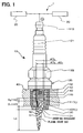
- a plasma ignition system 1 of the first embodiment includes a high voltage power having a discharge power source 20 and a plasma generation power source 30, and a plasma ignition plug 10.
- the plasma ignition plug 10 includes a center electrode 110, a cylindrical insulating member 120, which insulates and holds the center electrode 110, and an annular ground electrode 130, which covers the insulating member 120.
- a lower end portion of the center electrode 110 is formed into a shaft shape having a diameter of ⁇ D1.
- a leading end side of the center electrode 110 is formed from a high melting point material such as Fe (iron) or Ni (nickel), and a center-electrode axis 112 including a highly conductive metallic material such as Cu (copper) or a ferrous material is formed in the center electrode 110.
- a high melting point material such as Fe (iron) or Ni (nickel)
- a center-electrode axis 112 including a highly conductive metallic material such as Cu (copper) or a ferrous material is formed in the center electrode 110.
- the insulating member 120 is formed from, for example, highly-pure alumina, which is excellent in heat resistance, mechanical strength, dielectric strength at high temperature, and heat conductivity.
- the cylindrical discharge space 140 extending downward from a leading end surface of the center electrode 110 and having an inner diameter D1 and length G1 is formed on a leading end side of the insulating member 120.
- a center-electrode locking part which catches the housing 135 via a packing member for maintaining airtightness between the insulating member 120 and a housing 135, is formed in a halfway area of the insulating member 120.
- An insulating member head portion which insulates the center electrode 110 from the housing 135 and prevents high voltage from escaping to other areas than the center electrode 110, is formed on a rear end side of the insulating member 120.
- a leading end portion of the housing 135 covers an outer circumference of the insulating member 120, and an annular ground electrode 130, a leading end of which is crooked inward, is formed at the leading end portion of the housing 135.
- a housing thread part 132 for fixing the plasma ignition plug 10 to a wall surface (engine block 40) of an internal combustion engine (not shown) such that the ground electrode 130 is exposed to the inside of the engine and for putting the ground electrode 130 and the engine block 40 into a electrically grounded state is formed on an outer peripheral part of a halfway area of the housing 135.
- a housing hexagon head part 133 for fastening the housing thread part 132 is formed on an outer peripheral part of a rear end side of the housing 135.
- the ground electrode 130 has a ground electrode opening 131, which communicates with the inside of the insulating member 120 and is opposed to the discharge space 140.
- An opening diameter ⁇ D1 of a lower end of the recess portion 111 of the center electrode 110 is generally the same as an inner diameter ⁇ D2 of the insulating member 120, which defines the discharge space 140.
- a relationship between the recess portion opening diameter ( ⁇ D1) and the insulating member inner diameter ( ⁇ D2) may satisfy D2 ⁇ D1, or the recess portion 111 and the insulating member 120 may be formed such that a difference in level is not caused between an inner surface of the recess portion 111 and an inner surface of the insulating member 120 due to a difference between the recess portion opening diameter ( ⁇ D1) and the insulating member inner diameter ( ⁇ D2).
- volume of the recess portion 111 at its portion close to the discharge path is maximized, the supplied energy is most efficiently utilized for putting the gas in the discharge space 140 and the recess portion 111 into the plasma state.
- a relationship between an outer diameter ⁇ D3 of the center electrode 110 at its portion serving as an inner circumferential wall of the recess portion 111 and the inner diameter ⁇ D2 of the insulating member 120 defining the discharge space 140 is set to satisfy D2 ⁇ D3 ⁇ 2xD2.
- the electric field density at a portion of the recess portion 111 serving as its vertical wall becomes high and consequently, the discharge voltage is made even lower.
- a relationship among a distance G1 from a lower end surface of the center electrode 110 to a surface of the ground electrode 120 at a boundary between the ground electrode 130 and a lower end portion of the insulating member 120, the depth G2 of the recess portion 111, volume V1 of the discharge space 140, and the volume V2 of the recess portion 111 is set to satisfy G2 ⁇ G1 and V1 ⁇ V1 +V2 ⁇ 2xV1.
- the recess portion 111 When the recess portion 111 is enlarged too much, an amount of the gas that is put into the plasma state becomes smaller than the total volume Vt of the volume V1 of the discharge space 140 and the volume V2 of the recess portion 111, since an amount of gas that is able to be ionized by a constant discharge voltage is limited. Accordingly, the volume V1 and the volume V2 have their optimum values. More specifically, by forming the recess portion 111 to satisfy the above-prescribed ranges, the gas in the discharge space 140 and the gas in the recess portion 111 are most efficiently put into the plasma state. As a result, the plasma ignition system 1, which is extremely excellent in durability and excellent in ignition stability of the engine, is realized.
- polarities of the discharge power source 20 and the plasma generation power source 30 are set such that the center electrode 110-side serves as a positive pole and the ground electrode 130-side serves as a negative pole.
- the discharge power source 20 includes a first battery 21, an ignition key 22, an ignition coil 23, an igniter having a transistor, and an electronic control unit (ECU) 25.
- the discharge power source 20 is connected to the plasma ignition plug 10 through a first rectifying device 26. A positive pole side of the first battery 21 is grounded.
- the plasma generation power source 30 includes a second battery 31, a resistance 32, and a plasma generation capacitor 33.
- the plasma generation power source 30 is connected to the plasma ignition plug 10 through a second rectifying device 34.
- a negative pole side of the second battery 31 is grounded.
- a negative and low primary voltage is applied to a primary coil 231 of the ignition coil 23 from the first battery 21 in response to an ignition signal from the ECU 25.
- the primary voltage is cut off by switching of an ignition coil drive circuit 24, a magnetic field in the ignition coil 23 changes and accordingly, a positive secondary voltage ranging from 10 to 30kV is induced in a secondary coil 232 of the ignition coil 23 due to a self-induction effect.
- the plasma generation capacitor 33 is charged by the second battery 31.
- the applied secondary voltage is larger than a discharge voltage proportional to a discharge distance 141 between the center electrode 110 and the ground electrode 130, electric discharge is started between both the electrodes and thereby gas in the discharge space 140 is put into a plasma state in a small region.
- the gas in the plasma state has conductivity and causes discharge of electric charge stored between both poles of the plasma generation capacitor 33. Accordingly, the gas in the discharge space 140 is further put into the plasma state and the above region is expanded.
- the gas in the plasma state has high temperature and pressure and is injected into a combustion chamber of the engine. Meanwhile, not only the gas in the discharge space 140 but also gas in the recess portion 111 is put in the plasma state of high temperature and pressure. Therefore, a plasma injection length Lp becomes very long.
- a collision angle of the positive ion 50 is shallow and thereby collision force of the positive ion 50 is mitigated because the opening 131 is disposed in a direction generally perpendicular to an injection direction of the gas in the plasma state.
- the ground electrode 130-side easily releases heat to the engine block 40 and is thereby easily cooled despite the collision with the high-temperature positive ion 50, so that the ground electrode 130 is resistant to its consumption caused by cathode sputtering.
- the positive ion 50 does not collide with a surface of the center electrode 110 serving as a positive pole because the positive ion 50 is repelled by the surface due to electrostatic repulsion. Only an electron 51 having small mass collides with the surface of the center electrode 110 and accordingly erosion due to the cathode sputtering does not take place easily.
- a first comparative example is configured not to include a recess portion 111
- a second comparative example is configured such that an outer diameter ⁇ D3 of a center electrode 110 is equal to an inner diameter ⁇ D1 of an insulating member 120 and that an inner diameter ⁇ D2 of a recess portion 111 is smaller than the outer diameter ⁇ D3 of the center electrode 110.
- the first embodiment is configured such that the outer diameter ⁇ D3 of the center electrode 110 is larger than the inner diameter ⁇ D1 of the insulating member 120 and that the inner diameter ⁇ D2 of the recess portion 111 is equal to the inner diameter ⁇ D1 of the insulating member 120, and a second embodiment of the invention is configured such that the depth G2 of the recess portion 111 is larger than the first embodiment.
- Table 1 1st comparative example 2nd comparative example 1st embodiment 2nd embodiment Outer dia. of center electrode ⁇ D3 1.3mm 1.3mm 2.0mm 2.0mm Inner dia. of discharge space ⁇ D2 1.3mm 1.3mm 1.3mm 1.3mm Inner dia.
- an electric field density of a portion defining a vertical wall of the recess portion 111 is increased due to the existence of the recess portion 111, and thereby electricity is easily discharged.
- the inner diameter ⁇ D2 of the recess portion 111 is generally equal to the inner diameter ⁇ D1 of the insulating member 120, a distance between a corner portion of an opening at a lower end of the recess portion 111 and a creeping-discharge path formed to creep on a surface of an inner circumferential wall of the insulating member 120 is extremely small, and a discharge voltage V becomes even lower.
- FIG. 3 shows the result of measurement of the plasma injection length Lp with respect to the first comparative example, the second comparative example, the first embodiment, and the second embodiment. As shown in FIG. 3 , according to the invention, the plasma injection length Lp is most lengthened.
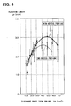
- FIG. 4 is a characteristic diagram illustrating the result of the measurement of the plasma injection length Lp when discharge space total volume Vt is changed in a more detailed manner to verify the effects of the invention.
- the plasma injection length Lp gradually becomes longer as the discharge space total volume Vt becomes larger. Nevertheless, when the discharge space total volume Vt becomes equal to or larger than certain volume, the plasma injection length Lp becomes conversely shorter. Also, the plasma injection length Lp becomes longer in the case where the recess portion 111 is formed than in the case where the recess portion 111 is not formed, despite the same discharge space total volume Vt.
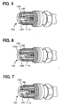
- FIGS. 5 to 10 is a partly cutaway perspective view illustrating a main portion of a plasma ignition plug 10 used for a plasma ignition system 1 according to embodiments of the invention.
- their basic configurations are the same as the first embodiment, and a shape of an inner circumferential wall of a recess portion 111 of the plasma ignition plug 10 or an inner circumferential wall of an insulating member 120 is different from the first embodiment.
- a minimum distance from a surface of an uppermost part of the ground electrode 130 to a surface of a lowermost part of the center electrode 110 is the discharge distance 141 and accordingly, the discharge voltage is constant.
- the electrons 51 are emitted to the space defined by the inner circumferential wall of the recess portion 111, as well as to the discharge space 140 defined by an inner circumferential wall of the insulating member 120. Accordingly, the volume of the gas, which is put into the plasma state, is increased without increasing the discharge voltage.
- the center electrode 110 serves as a positive pole.
- the positive ion 50 having large mass is repelled by the center electrode 110 due to the electrostatic repulsion, and only the electron 51 having small mass collides with the center electrode 110. Consequently, the center electrode 110 is not easily eroded due to the cathode sputtering. Therefore, according to the invention, the durability of the plasma ignition system 1 is improved, and an amount of the gas that is put into the plasma state is increased with respect to a constant discharge voltage, so that the ignitionability of the engine is improved.
- the ground electrode 130 serving as a negative pole can be eroded due to the cathode sputtering, a collision angle of the positive ion 50 with the ground electrode 130 is shallow, and thus the collision force of the positive ion 50 is eased, because the surface of the ground electrode 130 faces in a direction generally perpendicular to the injection direction of the gas in the plasma state.
- the ground electrode 130-side easily releases heat to the grounded part of the engine, the consumption of the electrodes is not easily caused by the cathode sputtering compared to when the center electrode 110 is used as a negative pole in a conventional manner.
- the durability of the plasma ignition system 1 that is excellent in ignition stability is further improved.
- a center-electrode recess portion 111a is formed in a shape of a half-ellipse spherical surface.
- the following advantageous effect is produced in addition to a similar effect to the first embodiment. That is, when the center-electrode recess portion 111 a is formed to have the same recess portion volume V2 as the first embodiment, a surface area of an inner circumferential wall of the center-electrode recess portion 111a is larger than the first embodiment. Accordingly, it is expected that a probability of occurrence of gas ionized by an electron released into the center-electrode recess portion 111 a is made high.
- a center-electrode recess portion 111 b is formed in a conical shape.
- a center-electrode recess portion 111 c is formed in a shape of a truncated cone.
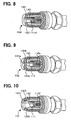
- a plasma ignition plug 10d according to a fifth embodiment of the invention is configured such that a wall surface of a center-electrode recess portion 111 d is partly notched and an insulating member is inserted therebetween so as to achieve multipolarity.
- an inner circumferential wall of an insulating member 120e is formed in a conical shape, in which an inner diameter of the insulating member 120e becomes smaller in a direction from a center-electrode 110e-side toward a ground electrode 130e-side.
- the gas in the plasma state having high temperature and pressure, which is generated in the discharge space 140 is injected to be squeezed out through the narrow ground electrode opening 131e, the plasma injection length Lp becomes even longer, and as a result, the ignition stability is expected to be improved in the stratified combustion.
- an inner circumferential wall of an insulating member 120f is formed in a shape of a trumpet, in which an inner diameter of the insulating member 120f becomes larger in a direction from a center electrode 110f-side toward a ground electrode 130f-side.
- the invention is not limited to the above embodiments, and may be appropriately changed without departing from the scope of the invention.
- the plasma ignition system including a single plasma ignition plug is described.
- the invention may also be applied to a multiple cylinder engine including many ignition plugs.
- examples using the high voltage power having a plurality of power sources, that is, the discharge power source 20 and the plasma generation power source 30 are described.
- a power source for the application of high voltage and a power source for supply of a high current may constitute a single power source.
- a plasma ignition system (1) includes an ignition plug (10) attached to an engine and a high-voltage supply (20, 30).
- the plug includes a center electrode (110) serving as a positive pole, a ground electrode (130) serving as a negative pole, and an insulating member (120) insulating the center electrode from the ground electrode and defining a discharge space (140) therein. At least a part of a surface of the center electrode faces the space, and at least a part of a surface of the ground electrode faces the discharge space.
- the plug puts gas in the space into a plasma state and injects the gas into the engine as a result of application of high voltage and supply of a large current to the plug by the high-voltage supply.
- the center electrode has a recess portion (111) opposed to the space and recessed in a direction opposite to an injection direction.
Landscapes
- Spark Plugs (AREA)
- Ignition Installations For Internal Combustion Engines (AREA)
Claims (7)
- Système d'allumage à plasma (1) pour un moteur à combustion interne, comprenant :une bougie d'allumage (10) fixée sur le moteur ; etune alimentation à haute énergie (20, 30) qui alimente la bougie d'allumage (10) en énergie électrique, dans lequel la bougie d'allumage (10) comprend :une électrode centrale (110) ;une électrode de masse (130) ; etun élément isolant (120) qui isole l'électrode centrale (110) de l'électrode de masse (130) et définit un espace de décharge (140) dans celui-ci, dans lequel :l'électrode centrale (110) et l'électrode de masse (130) sont disposées de manière qu'au moins une partie d'une surface de l'électrode centrale (110) soit face à l'espace de décharge (140) et qu'au moins une partie d'une surface de l'électrode de masse (130) soit face à l'espace de décharge (140) ;la bougie d'allumage (10) est configurée pour libérer l'énergie électrique, qui est délivrée à la bougie d'allumage (10) par l'alimentation à haute énergie (20, 30), dans une chambre de combustion du moteur de manière à effectuer un allumage dans le moteur ;l'électrode centrale (110) est configurée pour servir comme un pôle positif ;l'électrode de masse (130) est configurée pour servir comme un pôle négatif ;l'électrode centrale (110) a une portion de cavité (111), qui est en regard de l'espace de décharge (140) et évidée dans une direction opposée à une direction d'injection dans laquelle le gaz est injecté dans le moteur ;l'élément isolant (120) a une portion de définition d'espace de décharge, qui définit l'espace de décharge (140); etcaractérisé en ce qu'une relation entre :un diamètre d'ouverture de portion de cavité (ϕD1), qui est un diamètre d'ouverture de la portion de cavité (111) au niveau d'une portion d'extrémité axiale de celle-ci faisant face à l'espace de décharge (140) ;un diamètre intérieur d'élément isolant (ϕD2), qui est un diamètre intérieur de la portion de définition d'espace de décharge d'une portion d'extrémité axiale de celle-ci sur un côté de l'électrode centrale (110) ; etun diamètre extérieur d'électrode centrale (ϕD3), qui est un diamètre extérieur de l'électrode centrale (110) au niveau de la portion de cavité (111) de celle-ci,satisfait les expressions suivantes :

et étant entendu que ϕD1 est le diamètre d'ouverture de portion de cavité ; ϕD2 est le diamètre intérieur d'élément isolant ; et ϕD3 est le diamètre extérieur d'électrode centrale.
 - Système d'allumage à plasma (1) selon la revendication 1, dans lequel :l'électrode centrale (110) est formée sous une forme d'un arbre ;l'élément isolant (120) est formé sous une forme cylindrique ;l'élément isolant (120) couvre une périphérie de l'électrode centrale (110) et s'étend ultérieurement dans la direction d'injection par rapport à l'électrode centrale (110) de manière à définir l'espace de décharge (140) ;l'électrode de masse (130) est formée sous une forme cylindrique ;l'électrode de masse (130) couvre une périphérie de l'élément isolant (120) et s'étend ultérieurement dans la direction d'injection par rapport à l'élément isolant (120) pour être formée en une portion d'ouverture (131) ; etla portion d'ouverture (131) fait face à l'espace de décharge (140) et communique avec l'espace de décharge (140).
- Système d'allumage à plasma (1) selon la revendication 2, dans lequel une paroi circonférentielle intérieure de l'élément isolant (120) qui définit l'espace de décharge (140) est formée sous une forme d'un cône généralement circulaire, dont un diamètre diminue dans la direction d'injection.
- Système d'allumage à plasma (1) selon la revendication 2, dans lequel une paroi circonférentielle intérieure de l'élément isolant (120) qui définit l'espace de décharge (140) est formée sous une forme d'un cône généralement circulaire, dont un diamètre augmente dans la direction d'injection.
- Système d'allumage à plasma (1) selon l'une quelconque des revendications 1 à 4, dans lequel :une relation entre le diamètre extérieur d'électrode centrale (ϕD3), qui est un diamètre extérieur de l'électrode centrale (110) au niveau de la portion de cavité (111) de celle-ci, et le diamètre intérieur d'élément isolant (ϕD2), qui est un diamètre intérieur de la portion de définition d'espace de décharge, satisfait l'expression suivante :

étant entendu que ϕD2 est le diamètre intérieur d'élément isolant et ϕD3 est le diamètre extérieur d'électrode centrale. - Système d'allumage à plasma (1) selon l'une quelconque des revendications 1 à 5, dans lequel une relation entre une distance de décharge (G1), qui est une distance d'une extrémité axiale de l'électrode centrale (110) qui fait face à l'espace de décharge (140) à une surface de l'électrode de masse (130) au niveau d'une frontière entre l'électrode de masse (130) et une extrémité axiale de l'élément isolant (120) dans la direction d'injection, une profondeur de portion de cavité (G2), qui est une profondeur de la portion de cavité (111), un volume d'espace de décharge (V1), qui est un volume de l'espace de décharge (140), et un volume de portion de cavité (V2), qui est un volume de la portion de cavité (111), satisfait les expressions suivantes :

et
étant entendu que : G1 est la distance de décharge ; G2 est la profondeur de portion de cavité ; V1 est le volume d'espace de décharge ; et V2 est le volume de portion de cavité. - Système d'allumage à plasma (1) selon l'une quelconque des revendications 1 à 6, dans lequel :l'alimentation à haute énergie (20, 30) comprend une alimentation haute tension (20, 30) qui applique une haute tension à la bougie d'allumage (10) et délivre un courant élevé à la bougie d'allumage (10) ; etla bougie d'allumage (10) est configurée pour mettre un gaz dans l'espace de décharge (140) dans un état de plasma à haute température et pression et pour injecter le gaz dans le moteur comme conséquence de l'application de la haute tension à la bougie d'allumage (10) et de la fourniture du courant élevé à la bougie d'allumage (10) par l'alimentation haute tension (20, 30).
Applications Claiming Priority (1)
| Application Number | Priority Date | Filing Date | Title |
|---|---|---|---|
| JP2007185670A JP4424384B2 (ja) | 2007-07-17 | 2007-07-17 | プラズマ式点火装置 |
Publications (3)
| Publication Number | Publication Date |
|---|---|
| EP2017930A2 EP2017930A2 (fr) | 2009-01-21 |
| EP2017930A3 EP2017930A3 (fr) | 2012-10-31 |
| EP2017930B1 true EP2017930B1 (fr) | 2014-03-12 |
Family
ID=39791030
Family Applications (1)
| Application Number | Title | Priority Date | Filing Date |
|---|---|---|---|
| EP08160493.6A Ceased EP2017930B1 (fr) | 2007-07-17 | 2008-07-16 | Système d'ignition à plasma |
Country Status (3)
| Country | Link |
|---|---|
| US (1) | US7948158B2 (fr) |
| EP (1) | EP2017930B1 (fr) |
| JP (1) | JP4424384B2 (fr) |
Families Citing this family (6)
| Publication number | Priority date | Publication date | Assignee | Title |
|---|---|---|---|---|
| BRPI0601626C1 (pt) * | 2006-05-08 | 2009-11-24 | Vivaldo Mazon | sistema de ignição contìnua para motor a combustão interna por meio de plasma |
| JP5715705B2 (ja) | 2010-10-28 | 2015-05-13 | フェデラル−モーグル・イグニション・カンパニーFederal−Mogul Ignition Company | 非熱プラズマ点火アークの抑制 |
| JP6572868B2 (ja) * | 2016-11-04 | 2019-09-11 | 株式会社豊田中央研究所 | 内燃機関の点火装置 |
| JP6709151B2 (ja) * | 2016-12-15 | 2020-06-10 | 株式会社デンソー | 点火制御システム及び点火制御装置 |
| CN114421284B (zh) * | 2022-03-30 | 2022-07-22 | 中国空气动力研究与发展中心计算空气动力研究所 | 一种气流冷却式多电极高能点火器 |
| CN114704416B (zh) * | 2022-04-12 | 2023-04-28 | 山东大学 | 一种多通道放电大面积分布式点火系统及方法 |
Family Cites Families (7)
| Publication number | Priority date | Publication date | Assignee | Title |
|---|---|---|---|---|
| US3581141A (en) | 1969-04-07 | 1971-05-25 | Ethyl Corp | Surface gap spark plug |
| JPS5635793U (fr) | 1979-08-27 | 1981-04-07 | ||
| JPS5635793A (en) | 1979-08-31 | 1981-04-08 | Mitsubishi Metal Corp | Electrolytic formation of verdigris on surface of copper or copper alloy |
| JPS5729089A (en) | 1980-07-29 | 1982-02-16 | Fujitsu Ltd | Method of indicating and controlling project system display unit |
| JP4483660B2 (ja) * | 2005-04-05 | 2010-06-16 | 株式会社デンソー | 内燃機関用点火装置 |
| JP2007134127A (ja) | 2005-11-09 | 2007-05-31 | Denso Corp | 点火プラグ及び点火装置 |
| JP4778301B2 (ja) | 2005-11-22 | 2011-09-21 | 日本特殊陶業株式会社 | プラズマジェット点火プラグおよびその点火装置 |
-
2007
- 2007-07-17 JP JP2007185670A patent/JP4424384B2/ja not_active Expired - Fee Related
-
2008
- 2008-07-16 EP EP08160493.6A patent/EP2017930B1/fr not_active Ceased
- 2008-07-17 US US12/175,117 patent/US7948158B2/en not_active Expired - Fee Related
Also Published As
| Publication number | Publication date |
|---|---|
| US20090021133A1 (en) | 2009-01-22 |
| EP2017930A3 (fr) | 2012-10-31 |
| JP4424384B2 (ja) | 2010-03-03 |
| EP2017930A2 (fr) | 2009-01-21 |
| US7948158B2 (en) | 2011-05-24 |
| JP2009026489A (ja) | 2009-02-05 |
Similar Documents
| Publication | Publication Date | Title |
|---|---|---|
| US20080141967A1 (en) | Plasma ignition device | |
| EP1837966B1 (fr) | Bougie d'allumage par jet de plasma et système d'allumage | |
| EP2017930B1 (fr) | Système d'ignition à plasma | |
| KR101446725B1 (ko) | 복합 스파크 플러그 | |
| US4396855A (en) | Plasma jet ignition plug with cavity in insulator discharge end | |
| US6380664B1 (en) | Spark plug having an internal conductor configuration | |
| EP1192354B1 (fr) | Systeme d'allumage bimodal avec allumeur a deplacement de l'etincelle | |
| US4337408A (en) | Plasma jet ignition plug | |
| US4388549A (en) | Plasma plug | |
| EP2365594B1 (fr) | Bougie d'allumage par jet de plasma et système d'ignition | |
| CN103262370B (zh) | 具有特定形状的绝缘体的电晕点火器 | |
| US7741761B2 (en) | Radiofrequency plasma spark plug | |
| CN103444024A (zh) | 具有可控的电晕形成位置的电晕点火器 | |
| US6329743B1 (en) | Current peaking sparkplug | |
| US4308488A (en) | Plasma jet ignition system | |
| EP0560603B1 (fr) | Dispositif de détection de ratés d'allumage pour un moteur à combustion interne | |
| JP4760780B2 (ja) | プラズマ式点火装置 | |
| JP2009097500A (ja) | プラズマ式点火装置 | |
| JP4777463B2 (ja) | プラズマジェット点火プラグ | |
| US20080284304A1 (en) | Spark plug for internal combustion engine | |
| GB2063363A (en) | Spark plug for internal combustion engine | |
| JP2008186743A (ja) | プラズマ式点火装置 | |
| JP2009146636A (ja) | 点火装置 | |
| US20120212131A1 (en) | Plasma jet spark plug and ignition system | |
| JP7202002B2 (ja) | 点火プラグ |
Legal Events
| Date | Code | Title | Description |
|---|---|---|---|
| PUAI | Public reference made under article 153(3) epc to a published international application that has entered the european phase |
Free format text: ORIGINAL CODE: 0009012 |
|
| AK | Designated contracting states |
Kind code of ref document: A2 Designated state(s): AT BE BG CH CY CZ DE DK EE ES FI FR GB GR HR HU IE IS IT LI LT LU LV MC MT NL NO PL PT RO SE SI SK TR |
|
| AX | Request for extension of the european patent |
Extension state: AL BA MK RS |
|
| PUAL | Search report despatched |
Free format text: ORIGINAL CODE: 0009013 |
|
| AK | Designated contracting states |
Kind code of ref document: A3 Designated state(s): AT BE BG CH CY CZ DE DK EE ES FI FR GB GR HR HU IE IS IT LI LT LU LV MC MT NL NO PL PT RO SE SI SK TR |
|
| AX | Request for extension of the european patent |
Extension state: AL BA MK RS |
|
| RIC1 | Information provided on ipc code assigned before grant |
Ipc: H01T 13/50 20060101AFI20120926BHEP Ipc: F02P 9/00 20060101ALI20120926BHEP |
|
| 17P | Request for examination filed |
Effective date: 20130301 |
|
| AKX | Designation fees paid |
Designated state(s): DE FR |
|
| GRAP | Despatch of communication of intention to grant a patent |
Free format text: ORIGINAL CODE: EPIDOSNIGR1 |
|
| INTG | Intention to grant announced |
Effective date: 20130925 |
|
| GRAS | Grant fee paid |
Free format text: ORIGINAL CODE: EPIDOSNIGR3 |
|
| GRAA | (expected) grant |
Free format text: ORIGINAL CODE: 0009210 |
|
| AK | Designated contracting states |
Kind code of ref document: B1 Designated state(s): DE FR |
|
| REG | Reference to a national code |
Ref country code: DE Ref legal event code: R096 Ref document number: 602008030752 Country of ref document: DE Effective date: 20140424 |
|
| REG | Reference to a national code |
Ref country code: DE Ref legal event code: R097 Ref document number: 602008030752 Country of ref document: DE |
|
| PLBE | No opposition filed within time limit |
Free format text: ORIGINAL CODE: 0009261 |
|
| STAA | Information on the status of an ep patent application or granted ep patent |
Free format text: STATUS: NO OPPOSITION FILED WITHIN TIME LIMIT |
|
| REG | Reference to a national code |
Ref country code: DE Ref legal event code: R084 Ref document number: 602008030752 Country of ref document: DE |
|
| 26N | No opposition filed |
Effective date: 20141215 |
|
| REG | Reference to a national code |
Ref country code: DE Ref legal event code: R084 Ref document number: 602008030752 Country of ref document: DE Effective date: 20150203 |
|
| REG | Reference to a national code |
Ref country code: DE Ref legal event code: R097 Ref document number: 602008030752 Country of ref document: DE Effective date: 20141215 |
|
| REG | Reference to a national code |
Ref country code: FR Ref legal event code: PLFP Year of fee payment: 8 |
|
| REG | Reference to a national code |
Ref country code: FR Ref legal event code: PLFP Year of fee payment: 9 |
|
| REG | Reference to a national code |
Ref country code: FR Ref legal event code: PLFP Year of fee payment: 10 |
|
| REG | Reference to a national code |
Ref country code: FR Ref legal event code: PLFP Year of fee payment: 11 |
|
| PGFP | Annual fee paid to national office [announced via postgrant information from national office to epo] |
Ref country code: DE Payment date: 20200721 Year of fee payment: 13 Ref country code: FR Payment date: 20200722 Year of fee payment: 13 |
|
| REG | Reference to a national code |
Ref country code: DE Ref legal event code: R119 Ref document number: 602008030752 Country of ref document: DE |
|
| PG25 | Lapsed in a contracting state [announced via postgrant information from national office to epo] |
Ref country code: DE Free format text: LAPSE BECAUSE OF NON-PAYMENT OF DUE FEES Effective date: 20220201 |
|
| PG25 | Lapsed in a contracting state [announced via postgrant information from national office to epo] |
Ref country code: FR Free format text: LAPSE BECAUSE OF NON-PAYMENT OF DUE FEES Effective date: 20210731 |