EP2017936B1 - Système d'éolienne et son procédé de fonctionnement - Google Patents
Système d'éolienne et son procédé de fonctionnement Download PDFInfo
- Publication number
- EP2017936B1 EP2017936B1 EP07380213A EP07380213A EP2017936B1 EP 2017936 B1 EP2017936 B1 EP 2017936B1 EP 07380213 A EP07380213 A EP 07380213A EP 07380213 A EP07380213 A EP 07380213A EP 2017936 B1 EP2017936 B1 EP 2017936B1
- Authority
- EP
- European Patent Office
- Prior art keywords
- power
- current
- active
- reactive
- reference signal
- Prior art date
- Legal status (The legal status is an assumption and is not a legal conclusion. Google has not performed a legal analysis and makes no representation as to the accuracy of the status listed.)
- Active
Links
Images
Classifications
-
- F—MECHANICAL ENGINEERING; LIGHTING; HEATING; WEAPONS; BLASTING
- F03—MACHINES OR ENGINES FOR LIQUIDS; WIND, SPRING, OR WEIGHT MOTORS; PRODUCING MECHANICAL POWER OR A REACTIVE PROPULSIVE THRUST, NOT OTHERWISE PROVIDED FOR
- F03D—WIND MOTORS
- F03D7/00—Controlling wind motors
- F03D7/02—Controlling wind motors the wind motors having rotation axis substantially parallel to the air flow entering the rotor
- F03D7/028—Controlling wind motors the wind motors having rotation axis substantially parallel to the air flow entering the rotor controlling wind motor output power
- F03D7/0284—Controlling wind motors the wind motors having rotation axis substantially parallel to the air flow entering the rotor controlling wind motor output power in relation to the state of the electric grid
-
- F—MECHANICAL ENGINEERING; LIGHTING; HEATING; WEAPONS; BLASTING
- F03—MACHINES OR ENGINES FOR LIQUIDS; WIND, SPRING, OR WEIGHT MOTORS; PRODUCING MECHANICAL POWER OR A REACTIVE PROPULSIVE THRUST, NOT OTHERWISE PROVIDED FOR
- F03D—WIND MOTORS
- F03D7/00—Controlling wind motors
- F03D7/02—Controlling wind motors the wind motors having rotation axis substantially parallel to the air flow entering the rotor
- F03D7/0272—Controlling wind motors the wind motors having rotation axis substantially parallel to the air flow entering the rotor by measures acting on the electrical generator
-
- F—MECHANICAL ENGINEERING; LIGHTING; HEATING; WEAPONS; BLASTING
- F03—MACHINES OR ENGINES FOR LIQUIDS; WIND, SPRING, OR WEIGHT MOTORS; PRODUCING MECHANICAL POWER OR A REACTIVE PROPULSIVE THRUST, NOT OTHERWISE PROVIDED FOR
- F03D—WIND MOTORS
- F03D9/00—Adaptations of wind motors for special use; Combinations of wind motors with apparatus driven thereby; Wind motors specially adapted for installation in particular locations
- F03D9/20—Wind motors characterised by the driven apparatus
- F03D9/25—Wind motors characterised by the driven apparatus the apparatus being an electrical generator
- F03D9/255—Wind motors characterised by the driven apparatus the apparatus being an electrical generator connected to electrical distribution networks; Arrangements therefor
-
- H—ELECTRICITY
- H02—GENERATION; CONVERSION OR DISTRIBUTION OF ELECTRIC POWER
- H02J—ELECTRIC POWER NETWORKS; CIRCUIT ARRANGEMENTS OR SYSTEMS FOR SUPPLYING OR DISTRIBUTING ELECTRIC POWER; SYSTEMS FOR STORING ELECTRIC ENERGY
- H02J3/00—Circuit arrangements for AC mains or AC distribution networks
- H02J3/38—Arrangements for feeding a single network from two or more generators or sources in parallel; Arrangements for feeding already energised networks from additional generators or sources in parallel
- H02J3/381—Dispersed generators
-
- H—ELECTRICITY
- H02—GENERATION; CONVERSION OR DISTRIBUTION OF ELECTRIC POWER
- H02J—ELECTRIC POWER NETWORKS; CIRCUIT ARRANGEMENTS OR SYSTEMS FOR SUPPLYING OR DISTRIBUTING ELECTRIC POWER; SYSTEMS FOR STORING ELECTRIC ENERGY
- H02J3/00—Circuit arrangements for AC mains or AC distribution networks
- H02J3/38—Arrangements for feeding a single network from two or more generators or sources in parallel; Arrangements for feeding already energised networks from additional generators or sources in parallel
- H02J3/46—Controlling the sharing of generated power between the generators, sources or networks
- H02J3/50—Controlling the sharing of reactive power
-
- F—MECHANICAL ENGINEERING; LIGHTING; HEATING; WEAPONS; BLASTING
- F05—INDEXING SCHEMES RELATING TO ENGINES OR PUMPS IN VARIOUS SUBCLASSES OF CLASSES F01-F04
- F05B—INDEXING SCHEME RELATING TO WIND, SPRING, WEIGHT, INERTIA OR LIKE MOTORS, TO MACHINES OR ENGINES FOR LIQUIDS COVERED BY SUBCLASSES F03B, F03D AND F03G
- F05B2270/00—Control
- F05B2270/30—Control parameters, e.g. input parameters
- F05B2270/337—Electrical grid status parameters, e.g. voltage, frequency or power demand
-
- H—ELECTRICITY
- H02—GENERATION; CONVERSION OR DISTRIBUTION OF ELECTRIC POWER
- H02J—ELECTRIC POWER NETWORKS; CIRCUIT ARRANGEMENTS OR SYSTEMS FOR SUPPLYING OR DISTRIBUTING ELECTRIC POWER; SYSTEMS FOR STORING ELECTRIC ENERGY
- H02J2101/00—Supply or distribution of decentralised, dispersed or local electric power generation
- H02J2101/20—Dispersed power generation using renewable energy sources
- H02J2101/28—Wind energy
-
- Y—GENERAL TAGGING OF NEW TECHNOLOGICAL DEVELOPMENTS; GENERAL TAGGING OF CROSS-SECTIONAL TECHNOLOGIES SPANNING OVER SEVERAL SECTIONS OF THE IPC; TECHNICAL SUBJECTS COVERED BY FORMER USPC CROSS-REFERENCE ART COLLECTIONS [XRACs] AND DIGESTS
- Y02—TECHNOLOGIES OR APPLICATIONS FOR MITIGATION OR ADAPTATION AGAINST CLIMATE CHANGE
- Y02E—REDUCTION OF GREENHOUSE GAS [GHG] EMISSIONS, RELATED TO ENERGY GENERATION, TRANSMISSION OR DISTRIBUTION
- Y02E10/00—Energy generation through renewable energy sources
- Y02E10/70—Wind energy
- Y02E10/72—Wind turbines with rotation axis in wind direction
-
- Y—GENERAL TAGGING OF NEW TECHNOLOGICAL DEVELOPMENTS; GENERAL TAGGING OF CROSS-SECTIONAL TECHNOLOGIES SPANNING OVER SEVERAL SECTIONS OF THE IPC; TECHNICAL SUBJECTS COVERED BY FORMER USPC CROSS-REFERENCE ART COLLECTIONS [XRACs] AND DIGESTS
- Y02—TECHNOLOGIES OR APPLICATIONS FOR MITIGATION OR ADAPTATION AGAINST CLIMATE CHANGE
- Y02E—REDUCTION OF GREENHOUSE GAS [GHG] EMISSIONS, RELATED TO ENERGY GENERATION, TRANSMISSION OR DISTRIBUTION
- Y02E10/00—Energy generation through renewable energy sources
- Y02E10/70—Wind energy
- Y02E10/76—Power conversion electric or electronic aspects
Definitions
- the present invention relates to the field of wind energy systems and devices, and more specifically to the control of the way power generated by such systems and devices is supplied to a network or grid for distribution of the power.
- Wind energy systems include one or more wind power generators or turbines arranged to produce electrical energy by rotation induced by the wind.
- This electrical energy generated by one or more of these generators (for example, by several generators forming part of or constituting a so-called “wind farm"), is supplied to a grid or network for distribution of the energy.
- a large number of electrical power generators are connected to the same grid, and normally several power consumers are also connected to the grid.
- regulation of the way that wind power is injected and supplied to the grid has become increasingly important.
- a large number of patents, patent applications and other documents relate to how to control the supply of wind power to the network.
- the active power when operating in a mode with substantially zero reactive power, the active power is to be kept substantially constant. Now, this is impossible during, for example, a start-up phase.
- the start-up phase is not considered, keeping the active power constant is just a common way of regulating the power input to the grid: normally, a wind turbine is intended to produce its nominal active power output, which is then fed into the grid.
- the control method and system disclosed in US-B-6906431 could be considered to imply any contribution over this conventional prior art way of operating (or intending to operate, as a 100% constant power output is impossible in practice, due to the tolerances inherent in any real-world components and control system) a wind turbine or wind farm. The same applies, mutatis mutandis, to the operation of the wind turbine substantially without generation of active power and constant generation of reactive power.
- a further problem is that when operating a wind power system (such as a wind turbine or generator, or a wind farm comprising several wind turbines) with constant generation of power and injection of said power into the network, a decrease in the voltage will imply an increase in the current, if the power is to be kept constant.
- a wind power system such as a wind turbine or generator, or a wind farm comprising several wind turbines
- a decrease in the voltage will imply an increase in the current, if the power is to be kept constant.
- this in turn, basically requires that the components involved (conductors, transformers, etc.) are designed to withstand substantially higher currents than those that are normally present, which in turn implies additional costs,
- WO-A-2007/006565 discusses another way of controlling the power fed to the network from a wind power generator or a wind park.
- a current is supplied that is higher than the nominal current. In this way, more power can be supplied to the network.
- the idea behind the system disclosed in WO-A-2007/006565 is based on the fact that the components involved with the transfer of the generated power to the network are dimensioned in accordance with the nominal performance of the generator, not considering the fact that there are substantial variations in the voltage.
- the disclosed system is alleged to manage to increase the supply of power to the grid while not damaging the components due to excessively high current.
- a problem involved with the system disclosed in WO-A-2007/006565 is that it can give rise to an increased output of power that actually can damage the mechanical parts of the generator, due to, for example, an excessive torque.
- WO-A-2005/031160 discusses, inter alia, drawbacks involved with the system of DE-C-10059018 , corresponding to the prior art reference US-B-6906431 cited above, and proposes a way to achieve an adequate network support by supply of reactive power, while not exceeding the maximum current that the components of the wind power installation can support, and while assuring that a minimum amount of active power is kept available for security reasons, in order to keep the rotor speed of the wind turbine within certain limits.
- a first aspect of the invention relates to a wind power system, comprising an installation for generating electrical power from wind by means of at least one power generating turbine arranged to be rotated by wind (that is, the installation can basically comprise one wind turbine or an entire wind farm or part thereof), and a control system, said control system including a power controller for controlling the supply of electrical power (such as active and reactive power) from said wind power system (including the generating installation/turbine and the control system) to a network or grid for distribution of electrical power to a plurality of consumers.
- a power controller for controlling the supply of electrical power (such as active and reactive power) from said wind power system (including the generating installation/turbine and the control system) to a network or grid for distribution of electrical power to a plurality of consumers.
- the power controller comprises means for controlling a current (total current) supplied to or towards said network by said wind power system in accordance with at least one input parameter (for example, input parameters indicative of a desired amount of active power and reactive power to be supplied to the grid, or input parameters indicative of active power and phase angle -such as a desired cos ( ⁇ ) value or another indicator of the phase difference between current and voltage-).
- input parameter for example, input parameters indicative of a desired amount of active power and reactive power to be supplied to the grid, or input parameters indicative of active power and phase angle -such as a desired cos ( ⁇ ) value or another indicator of the phase difference between current and voltage-).
- the wind power system can, for example, comprise said installation connected to the network through a full converter, or a doubly-fed arrangement in which, for example, the installation can comprise one or more doubly-fed induction generators, such as a doubly-fed asynchronous machine.
- the power controller can be arranged to operate on a converter, be it a full converter or a converter connecting the rotor windings to the grid while the stator windings are connected substantially directly to the grid, bypassing the converter.
- the installation can also be any other kind of installation, such as a direct connected asynchronous generator, etc.
- the invention makes it possible to use the full current capability of the system (instead of looking only at the power), thus making it possible to increase the reactive power that can be supplied to the grid.
- the power controller is configured to keep the magnitude of the total current fed to the grid below a pre-set maximum magnitude (Imax), thereby preventing (or, at least, reducing) the risk for overcurrents in situations such as when there is a sudden voltage drop on the grid.
- the control system is arranged to establish, in view of a measured network voltage, a maximum amount of reactive power (Qmax) that can be supplied towards said network (considering the amount of active power that is currently supplied towards the grid, or that should be allowed to be fed towards the grid if required), said maximum amount of reactive power being selected so that said total current will not exceed said pre-set maximum magnitude (Imax).
- this current limitation restriction can be a restriction that prevails over the desired supply of active and reactive power, that is, if the desired active and reactive powers cannot be supplied without exceeding this current limit, the active power and/or the reactive power that is actually injected into the grid can be lower than the "desired" active and reactive powers (or the amount of active power and/or the phase angle can be modified with respect to the corresponding "desired” values).
- the current limitations were normally calculated on the basis of the power limitations of the system.
- advantage is taken of the full capability of the thermal design.
- the invention makes it possible to increase the reactive power that, under the prevailing conditions, can be supplied to the network.
- the power controller can be configured to operate the installation so that the wind power system supplies a predetermined amount of active power and a predetermined amount of reactive power towards the network in accordance with an active power reference signal or value and a reactive power reference signal or value (or a phase angle -or cos ( ⁇ )- reference signal or value), and the power controller can further be arranged to control the current and to adapt the active power and reactive power (or the phase angle/cos ( ⁇ ) so that the total current does not exceed said pre-set maximum magnitude (Imax).
- control system can be configured to increase the current supplied by the wind power system when there is a drop in the voltage at an output end of the wind power system, so as to continue to supply, as far as possible, said predetermined amounts of active power and reactive power, with the condition that the current may not exceed said pre-set maximum magnitude.
- the system can be arranged so as to give preference to the supply of active power or to the supply of reactive power in a situation in which it is not possible to supply the pre-established (or desired) amounts of said active power and reactive power without letting the total current exceed said pre-set maximum magnitude (Imax). That is, and under the prevailing condition that the total current does not exceed said pre-established limit, the system can supply, as far as possible, the desired amounts of active and reactive power and when this is no longer possible without increasing the total current beyond the relevant limit, the active power or the reactive power is first reduced, in accordance with established or pre-programmed preference criteria.
- the power controller can comprise a control loop for active power and a control loop for reactive power, wherein the control loop for active power can include means for generating an active current reference signal and wherein the control loop for reactive power can include means for generating a reactive current reference signal, wherein said control system further comprises means for limiting said active current reference signal and reactive current reference signal so as to prevent the total current from exceeding said pre-set maximum magnitude.
- Said power controller can be arranged to limit said active current reference signal and reactive current reference signal in accordance with at least one preference indicator stored in the system, so that preference is given to the limitation either of said active current reference signal or said reactive current reference signal.
- the power controller can be pre-programmed to conditionally or unconditionally give preference to the production of active power by giving preference to the limitation of the reactive current reference signal, thus as far as possible avoiding a reduction or limitation of the active current reference signal.
- the system is arranged so as to prevent the active power from increasing beyond a pre-determined level, thus allowing for a reduction of the apparent power when the phase angle between voltage and current decreases below a certain level, so as to prevent an excessive torque on mechanical components of the system.
- Another aspect of the invention relates to a method of operating a wind power system, substantially as defined in the corresponding independent claim. What has been stated above with reference to the system is also applicable to the method of the invention, mutatis mutandis.
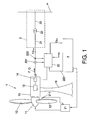
- Figure 1 schematically illustrates the structure of a system for wind power generation, including a wind turbine 1 with a rotor 11 with blades 12, the rotor being arranged so that it is made to rotate by the wind, thus producing the corresponding rotation, sometimes through a gearbox (not illustrated), of a generator 13 (namely, of a rotor part of said generator, said generator further comprising a stator part).
- the generator 13 produces an output AC voltage and can be connected to an electrical converter 14; currently, many different converter designs and arrangements are well known in this field and there is no need to further discuss them here; examples of converter arrangements that can be used within the framework of the present invention include full power converter arrangements (such as the one disclosed in US-A-5083039 ) and doubly-fed induction generator arrangements such as those using back-to-back power converters (such as the one disclosed in US-A-6137187 ), as well as systems such as the one disclosed in US-A-2003/0151259 ; the content of these documents is incorporated herein by reference.
- the gearbox, the generator 13 and the electrical converter 14 can all be arranged within a housing or "nacelle" 15, which is normally mounted on a tower 16.
- nacelle a housing or "nacelle" 15
- other arrangements are possible within the scope of the present invention.
- the electrical converter 14 converts the AC voltage at the output of the generator 13 into a DC voltage, which is subsequently converted into an AC voltage (and current) at an output end of the converter 14, which is connected to the grid or network 4 for distribution of the power generated by the wind turbine to the consumers.
- This connection takes place through a supply line 3, which can comprise (as illustrated in figure 1 ) components such as a low voltage line 31, a transformer 32 and a high voltage line 33.
- a supply line 3 which can comprise (as illustrated in figure 1 ) components such as a low voltage line 31, a transformer 32 and a high voltage line 33.
- the entire power to the grid passes through the converter.
- a part of the power passes through the converter and another part is supplied to the grid without passing through the converter, for example by a connection between the stator and the grid that by-passes the power converter, such as illustrated in, for example, figures 1 and 3 of US-A-2003/0151259 . All this is conventional and it is not considered necessary to describe further herein.
- the system for wind power generation comprises a general control system, which can also be fully or partly arranged within the housing 15, although it can also be external to the housing.
- this control system comprises a main controller 2, provided with the relevant software for the overall control of the system based on pre-stored information and on information provided by different sensors and, for example, on information or instructions from an external operator or operation software.
- This main controller 2 controls the operation of a pitch regulator 21, which is in charge of setting the pitch of the blades 12 of the rotor 11 on the basis of instructions received from the main controller and on information received from sensors 211 at the rotor.
- a power controller 22 that receives inputs from one or more current sensors 221 and voltage sensors 222.
- the power controller 22 operates the electrical converter 14 so as to provide the correct output power (active power P and reactive power Q) towards the grid, based on the current and voltage information provided by the respective current sensor 221 and voltage sensor 222, and on a power reference signal 223 provided by the main controller 2.
- the power controller can provide the relevant control signals to the converter 14 so as to keep the active and reactive power at the output end of said converter in line (as far as possible) with the power reference 223 received from the main controller.
- the current supplied to the grid is a critical factor, as an excessive current can cause heating and damage to the grid and to components of the supply line 3.
- a maximum current Imax is (pre)established, that should not be exceeded. If, for example, the voltage U drops on the supply line (for example, due to a short-circuit in the grid), to continue providing the same amount of active and reactive power would imply increasing the current, which could cause damage to components of the system.
- this problem has maybe been less relevant as the generator, traditionally, has been disconnected from the grid when there was a voltage drop on the grid. However, this is no longer the case: in fact, there is a trend among at least some network operators to actually require the generator to continue connected to the grid also throughout the duration of a grid failure, although sometimes without supplying power to the grid.
- the power controller 22 is arranged to operate on the converter so that, on the one hand, the active power P and the reactive power Q are, so far as possible, in line with what is determined by the power reference 223, but under the condition that the amplitude or magnitude of the total current (including the current component I P in phase with the voltage and the current component I Q that is out of phase by ⁇ /2 radians - 90 degrees- with regard to the voltage) does not exceed a pre-established maximum current magnitude (Imax).
- the power controller When the magnitude of the total current approaches said maximum current magnitude, the power controller operates the converter to limit I P and/or I Q (and thus, at a fixed voltage, the corresponding active power P and/or reactive power Q) so as to keep the total current within the relevant limits.
- the power controller 22 can, based on the measured current and voltage values and on the basis of the amount of active power that should be supplied (or available for supply) to the network, calculate a maximum amount of reactive power (Qmax) that can be supplied to the network, and provide the corresponding information to, for example, the main controller, which can use this information for calculating the power reference 223.
- the power controller 22 can be configured to give priority to the active power or to the reactive power, so as to reduce only one of them or one to a greater extent than the other one. For example, by reducing the angle between current and voltage, at a certain voltage drop the active power can be kept substantially constant and the total current can be kept under the corresponding maximum value, whereas less reactive power is supplied to the network 4, or vice versa.
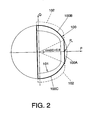
- Figure 2 is a diagram illustrating the power output to the grid from a system according to a preferred embodiment of the invention, wherein the horizontal axis represents the amount of active power (P) and the vertical axis the amount of reactive power (Q) supplied to the grid.
- the curve 100 represents the operation at nominal voltage U N (which in a typical system of this kind can be, for example, 690V at the output end of the converter 14).
- phase difference ⁇ between current and voltage (which can be conventionally controlled by the converter 14; for example, one way of controlling it is by controlling the active and reactive power, which thus gives a resulting phase angle ⁇ ), for a constant current amplitude and voltage amplitude, it is possible to move along the curved portion (100B, 100C) of the curve 100, varying the relation between the active power and the reactive power as desired.
- the mechanical system has been designed, in what regards its torque resistance, for example, to support a torque corresponding to this nominal power (with a corresponding safety margin). That is, it is not desired that the torque exceed the one corresponding to this nominal active power.
- the control system is programmed so that if cos ( ⁇ ) increases above the relevant value (for example, in figure 2 , if the angle ⁇ decreases towards zero and cos ( ⁇ ) thus increases from 0.9 towards 1), the active power is controlled (for example, by current control) not to exceed the nominal active power. This is represented by the vertical straight portion 100A of the curve 100.
- S will not be held constant but will be reduced when the angle ⁇ decreases towards zero, that is, when the reactive component is reduced towards zero, thus avoiding an excessive active power that could give rise to an excessive torque and to a corresponding risk of damage or wear on the mechanical part of the system, such as the drive train components (for example, the gearbox, main shaft, generator, etc.).
- the system has been designed to work at the nominal voltage, and the current limit is set so that the power output can be kept constant by increasing the current when the voltage decreases within certain limits (that is, by a certain maximum amount or percentage), and by decreasing the current when the voltage increases.
- the system can be designed for a voltage to be the nominal voltage U N ⁇ X%, such as U N ⁇ 10%, for example, 690V ⁇ 69V. That is, voltage fluctuations by ⁇ 10% can then be "accepted" by the system, which has been designed accordingly.
- the maximum current Imax can be set to be the nominal current I N * (1/0.9) ⁇ I N *1.11.
- the curve 101 schematically illustrates an operational curve in the case that the voltage decreases with, for example, twice the allowed amount, that is, in the example given above, by 20% instead of by the expected maximum variation of ⁇ 10%.
- Imax the allowed amount
- the apparent power is reduced to avoid potentially destructive overcurrents.
- the curve 102 represent an extended operating area obtained by means of the present invention, compared to the alternative prior art approach based on a constant apparent power S.
- Imax has been chosen so as to allow operation along the curve 100 at the lower end of the "expected" voltage range (for example, U N +10%), when the voltage is higher than the minimum voltage (of, for example, U N -10%), for example, at a voltage of U N or U N +10%, it is possible to increase the apparent power beyond the curve 100.
- the active power P is still to be limited to P N (for example, to maintain the torque within the pre-established limits on the basis of which the system was designed), but a higher (inductive or capacitive) reactive power Q can be generated and injected into the grid, which improves the flexibility of the system in what regards the reactive power support that it can provide to the grid.
- the power controller 22 can, based on the actual measured network voltage, the maximum magnitude Imax of the current and the active power P that is supplied or should be "available" for supply, establish a maximum reactive power Qmax, that will limit the corresponding power reference signals 223 sent to the power controller from the main controller.
- the maximum reactive power that can be supplied will depend on the measured voltage and on the active power that the system should be able to provide, and will be (further) limited by said maximum magnitude Imax of the current.
- the system does not only reduce the risk for problems and damages due to overcurrents (overheating) that could arise if the apparent power S was to kept constant (also at voltages lower than the ones "tolerated” by the design of the system), but also makes it possible to increase the reactive power that can be injected into the grid, thus enhancing the grid support capability of the system.
- the negative active power illustrated in figure 2 could correspond to internal losses in the generator and converter when the generator is substantially not driven by the wind and when thus no active power is produced by the system, which could nevertheless continue to be connected to the grid, consuming some active power to compensate for those losses, while injecting reactive power into the grid, for the purpose of supporting the grid.
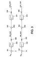
- Figure 3 schematically illustrates a part of what could be the power controller 22 of figure 1 . Basically, it comprises two control loops, one for the active power and one for the reactive power.
- the active power loop comprises a summation operator 301 for subtracting a first reference signal P REF corresponding to the "desired active power" (which can be limited so as to prevent the active power from increasing beyond a limit such as the nominal power P N limit discussed above with reference to figure 2 ) to be supplied to the grid, as established by the general control system (and, for example, communicated to the power controller as part of the power reference signal 223 provided by the main controller 2, as described above with reference to figure 1 ), with a measured active power P.
- a first reference signal P REF corresponding to the "desired active power" (which can be limited so as to prevent the active power from increasing beyond a limit such as the nominal power P N limit discussed above with reference to figure 2 ) to be supplied to the grid, as established by the general control system (and, for example, communicated to the power controller as part of the power reference signal 223 provided by the main controller 2, as described above with reference to figure 1 ), with a measured active power P.
- the difference is supplied to an active power PID controller 302, which produces an active current reference (IRQ_REF) which is supplied to summation operator 303 where it is compared to the measured active current (IRQ), whereafter a corresponding difference signal is supplied to the active current PID controller 304, producing an output reference voltage (URQ_REF) which is used to control the converter (for example, it can be supplied to control the pulse width modulation of a conventional converter system).
- IRQ_REF active current reference
- UTRQ_REF output reference voltage
- the reactive power loop comprises a summation operator 401 for comparing a first reference signal Q REF corresponding to the "desired reactive power" (for example, corresponding to part of the power reference signal 223 provided by the main controller 2, as described above with reference to figure 1 ) to be supplied to the grid, with a measured reactive power Q.
- the difference is supplied to a reactive power PID controller 402, which produces a reactive current reference (IRD_REF) which is supplied to a summation operator 403 where it is compared to the measured reactive current (IRD), whereafter a corresponding difference signal is supplied to the reactive current PID controller 304, producing an output reference voltage (URD_REF) which is also used to control the converter (for example, by pulse width modulation).
- the power control system further comprises an active current limiter 305 and a reactive current limiter 405, arranged to guarantee that the total current shall not exceed a certain threshold, by limiting the reference currents (the output signals from the active 302 and reactive 402 power PID controllers) accordingly.
- these current limiters 305/405 it is possible to prevent the total current from exceeding a certain threshold.
- the value of IRQ_REF 2 + IRD_REF Q 2 shall not exceed a certain threshold, corresponding to the maximum magnitude (Imax) of the total current.
- the two current limiters can be coordinated so that preference is given to the active or to the reactive current, depending on, for example, whether preference is to be given to active power or to reactive power to be supplied to the grid.
- the preference can, for example, be set by setting a parameter giving a higher priority either to the reactive or to the active power generation.
- the limit can be set so as to achieve the production of nominal active power and the rest of the "available" current can be used for the supply of reactive power, to the extent that it is desired in order to, for example, provide reactive power support to the network.
- the "available" current for reactive power I Q-available can at any moment be determined by the formula I Q - AVAILABLE + Imax 2 + I P 2 where Imax is the above-mentioned maximum current magnitude, and I P is the active current provided to the grid.
- a further set of limiters 306/406 can be provided at the output of the current PID controllers 304/404, to limit the voltage reference to the converter system to avoid overmodulation of the converter system, thus avoiding higher harmonics.
Landscapes
- Engineering & Computer Science (AREA)
- Power Engineering (AREA)
- Life Sciences & Earth Sciences (AREA)
- Sustainable Development (AREA)
- Sustainable Energy (AREA)
- Chemical & Material Sciences (AREA)
- Combustion & Propulsion (AREA)
- Mechanical Engineering (AREA)
- General Engineering & Computer Science (AREA)
- Control Of Eletrric Generators (AREA)
- Wind Motors (AREA)
- Supply And Distribution Of Alternating Current (AREA)
Claims (16)
- Système d'énergie éolienne, comprenant une installation (1) pour la production d'énergie électrique à partir du vent grâce à au moins une turbine productrice d'énergie, conçue pour tourner sous l'effet de l'action du vent; un système de contrôle (2, 21, 22), doté d'un contrôleur de puissance (22) destiné à gérer l'alimentation en énergie électrique provenant du système d'énergie éolienne d'un réseau (4), pour sa distribution à de multiples clients, où le contrôleur de puissance est doté de moyens pour le contrôle d'un courant alimentant ledit réseau provenant du système d'énergie éolienne, conformément à au moins un paramètre d'entrée (223),
Dans lequel
le contrôleur de puissance (22) est configuré de sorte à maintenir l'amplitude du courant total fourni au réseau en dessous d'un niveau prédéterminé (Imax),
dans lequel le système de contrôle est prévu pour déterminer, eu égard à la tension mesurée du réseau et à la puissance active fournie au réseau, une quantité maximum de puissance réactive (Qmax) pouvant être fournie au réseau, laquelle quantité de puissance réactive maximum étant déterminée afin de ne pas dépasser l'amplitude maximum prédéterminée (Imax),
Le système se caractérise par sa capacité à éviter que la puissance active ne dépasse un niveau prédéterminé (PN), le système de contrôle est configuré pour permettre une diminution de la puissance apparente lorsque l'angle de phase entre la tension et le courant chute sous un certain niveau, afin d'éviter un couple trop important sur les éléments mécaniques du système. - Système d'énergie éolienne selon la revendication 1, dans lequel le courant total est déterminé par la formule

dans lequel I est l'amplitude du courant total, Ip l'amplitude d'une composante du courant en phase avec la tension et IQ est l'amplitude d'une composante du courant avec une différence de phase de ± π/2 radians eu égard à la tension. - Système d'énergie éolienne selon les revendications 1 ou 2, dans lequel le contrôleur de puissance est configuré pour faire fonctionner le système d'énergie éolienne de façon à fournir une quantité de puissance active (P) et de puissance réactive (Q) prédéterminée au réseau, conformément à un signal de puissance active de référence et à un signal de puissance réactive de référence, où le contrôleur de puissance est également prévu pour contrôler le courant fourni par le système d'énergie éolienne et adapter la puissance active (P) et la puissance réactive (Q) pour que le courant total ne dépasse pas une amplitude maximum (Imax) prédéterminée.
- Système d'énergie éolienne selon les revendications 1 ou 2, dans lequel le contrôleur de puissance est configuré pour faire fonctionner le système d'énergie éolienne de façon à fournir une quantité de puissance active (P) et de puissance réactive (Q) prédéterminée au réseau, conformément à un signal d'angle de phase de référence et un signal de puissance réactive de référence, où le contrôleur de puissance est également prévu pour contrôler le courant fourni par le système d'énergie éolienne et adapter la puissance active (P) et l'angle de phase pour que le courant total ne dépasse pas une amplitude maximum (Imax) prédéterminée.
- Système d'énergie éolienne selon les revendications 3 ou 4, dans lequel le système de contrôle est configuré pour augmenter le courant fourni par le système d'énergie éolienne en cas de chute de tension sur une sortie de ce système, de façon à maintenir la fourniture, dans la mesure du possible, des quantités de puissance active et réactive, à condition que le courant ne dépasse pas une amplitude maximum (Imax) prédéterminée.
- Système d'énergie éolienne selon les revendications 3 à 5, prévu pour donner la préférence à l'alimentation en puissance active (P) ou en puissance réactive (Q) dans le cas où il s'avérerait impossible de fournir les quantités de puissance active et de puissance réactive prédéterminées, sans que le courant total franchisse le seuil d'amplitude maximum (Imax) prédéterminée.
- Système d'énergie éolienne selon l'une des revendications précédentes, dans lequel le contrôleur de puissance (22) inclut une boucle de régulation pour la puissance active et une autre pour la puissance réactive, dans lequel, la boucle de contrôle pour la puissance active comprend des moyens (302) de produire un signal de courant actif de référence (IRQ_REF) et la boucle de contrôle pour la puissance réactive comprend des moyens (402) de produire un signal de courant réactif de référence (IRD_REF), dans lequel le système de contrôle comprend également des moyens (305, 405) de limitation du signal de courant actif de référence et du signal de courant réactif de référence visant à éviter que le courant total ne dépasse l'amplitude maximum (Imax) prédéterminée.
- Système d'énergie éolienne selon la revendication 7, dans lequel le contrôleur de puissance (22) est prévu pour limiter le signal de courant actif et le signal de courant réactif de référence, selon au moins un indicateur de préférence stocké dans le système, où la préférence est ainsi donnée à la limitation, soit à celle du signal de courant actif de référence, soit à celle du signal de courant réactif de référence.
- Méthode pour l'exploitation d'un système d'énergie éolienne comprenant une installation (1) pour la production d'énergie électrique à partir du vent grâce à au moins une turbine productrice d'énergie prévue pour tourner sous l'effet de l'action du vent de façon à fournir du courant à un réseau (4) pour la distribution d'énergie électrique à de multiples clients,
la méthode comprend plusieurs étapes
la première consiste à maintenir l'amplitude du courant total fourni au réseau sous une amplitude maximum (Imax) prédéterminée,
la seconde vise à établir, selon une tension de réseau mesurée et selon une puissance active fournie au réseau, une quantité de puissance réactive (Qmax) maximum, pouvant être fournie au réseau en question, laquelle quantité maximum de puissance réactive est établie de façon à ce que le courant total ne dépasse pas ladite amplitude maximum (Imax) prédéterminée,
Elle est caractérisée par la capacité à éviter l'augmentation de puissance active au-delà d'un niveau prédéterminé (PN) et permettre une diminution de la puissance apparente lorsque l'angle de phase entre la tension et le courant chute sous un certain niveau, afin d'éviter un couple trop important sur les éléments mécaniques du système. - Méthode selon la revendication 9, dans laquelle le courant total est déterminé par la formule

dans laquelle I est l'amplitude du courant total, Ip l'amplitude de la composante du courant en phase avec la tension, et IQ l'amplitude de la composante du courant avec une différence de phase de ± π/2 radians eu égard à la tension. - Méthode selon les revendications 9 ou 10, dans laquelle le système d'énergie éolienne fonctionne pour fournir une quantité prédéterminée de puissance active (P) et de puissance réactive(Q) au réseau conformément à un signal de puissance active de référence et un signal de puissance réactive de référence, et comprenant une étape de contrôle du courant et d'adaptation de la puissance active (P) et de la puissance réactive (Q) de façon à ce que le courant total ne dépasse pas une amplitude maximum (Imax) prédéterminée.
- Méthode selon les revendications 9 ou 10, dans laquelle le système d'énergie éolienne fonctionne pour fournir une quantité prédéterminée de puissance active (P) de puissance réactive (Q) au réseau, conformément à un signal de puissance active de référence et à un signal d'angle de phase de référence, et comprenant également une étape de contrôle du courant et d'adaptation de la puissance active (P) et de l'angle de phase de façon à ce que le courant total ne dépasse pas une amplitude maximum (Imax) prédéterminée.
- Méthode selon les revendications 11 ou 12, comprenant une étape d'augmentation du courant fourni par le système d'énergie éolienne en cas de chute de la tension sur une sortie de ce système, de façon à maintenir la fourniture, dans la mesure du possible, des quantités prédéterminées de puissance active et de puissance réactive, à condition que le courant ne dépasse pas une amplitude maximum (Imax) prédéterminée.
- Méthode selon les revendications 10 à 13, comprenant une étape consistant à donner la préférence à la fourniture de puissance active (P) ou de puissance réactive (Q) lorsqu'il s'avère impossible de fournir les quantités prédéterminées de puissance active ou réactive sans que le courant ne dépasse l'amplitude maximum (Imax) prédéterminée.
- Méthode selon les revendications 9 à 14, comprenant des étapes visant à produire (302), dans une boucle de contrôle de la puissance active, un signal de courant actif de référence (IRQ_REF)et, dans une boucle de contrôle de puissance réactive, un signal de courant réactif de référence, tout en limitant (305, 405) lesdits signaux de courant actif et réactif de référence, afin d'éviter que le courant total fourni au réseau ne dépasse l'amplitude maximum (Imax) prédéterminée.
- Méthode selon la revendication 15, comprenant une étape de limitation du signal de courant actif de référence et du signal de courant réactif de référence conformément à au moins un indicateur de préférence, afin que la préférence soit ainsi donnée à la limitation, soit à celle du signal de courant actif de référence, soit celle du signal de courant réactif de référence.
Priority Applications (6)
| Application Number | Priority Date | Filing Date | Title |
|---|---|---|---|
| DE602007009966T DE602007009966D1 (de) | 2007-07-16 | 2007-07-16 | Windkraftsystem und Betriebsverfahren dafür |
| ES07380213T ES2355660T3 (es) | 2007-07-16 | 2007-07-16 | Sistema de energía eólica y procedimiento para hacerlo funcionar. |
| AT07380213T ATE485616T1 (de) | 2007-07-16 | 2007-07-16 | Windkraftsystem und betriebsverfahren dafür |
| EP07380213A EP2017936B1 (fr) | 2007-07-16 | 2007-07-16 | Système d'éolienne et son procédé de fonctionnement |
| US12/144,750 US8008793B2 (en) | 2007-07-16 | 2008-06-24 | Wind power system and method of operating it |
| CN200810132396XA CN101350528B (zh) | 2007-07-16 | 2008-07-16 | 风力系统及其运行方法 |
Applications Claiming Priority (1)
| Application Number | Priority Date | Filing Date | Title |
|---|---|---|---|
| EP07380213A EP2017936B1 (fr) | 2007-07-16 | 2007-07-16 | Système d'éolienne et son procédé de fonctionnement |
Publications (2)
| Publication Number | Publication Date |
|---|---|
| EP2017936A1 EP2017936A1 (fr) | 2009-01-21 |
| EP2017936B1 true EP2017936B1 (fr) | 2010-10-20 |
Family
ID=39032120
Family Applications (1)
| Application Number | Title | Priority Date | Filing Date |
|---|---|---|---|
| EP07380213A Active EP2017936B1 (fr) | 2007-07-16 | 2007-07-16 | Système d'éolienne et son procédé de fonctionnement |
Country Status (6)
| Country | Link |
|---|---|
| US (1) | US8008793B2 (fr) |
| EP (1) | EP2017936B1 (fr) |
| CN (1) | CN101350528B (fr) |
| AT (1) | ATE485616T1 (fr) |
| DE (1) | DE602007009966D1 (fr) |
| ES (1) | ES2355660T3 (fr) |
Families Citing this family (45)
| Publication number | Priority date | Publication date | Assignee | Title |
|---|---|---|---|---|
| DE602006003994D1 (de) * | 2006-02-03 | 2009-01-15 | Siemens Ag | Verfahren zur Glättung von Wechselstrom aus einer Reihe von Energieerzeugungseinheiten sowie Windkraftanlage mit mehreren Windmühlen mit variabler Rotationsgeschwindigkeit |
| US7642666B2 (en) * | 2006-11-02 | 2010-01-05 | Hitachi, Ltd. | Wind power generation apparatus, wind power generation system and power system control apparatus |
| WO2008137836A1 (fr) * | 2007-05-04 | 2008-11-13 | The University Of Alabama | Commande de convertisseur d'éoliennes à vitesse variable |
| US8108155B2 (en) * | 2008-07-11 | 2012-01-31 | Vestas Wind Systems A/S | System for monitoring a restoration factor of a wind turbine population |
| CA2714887C (fr) * | 2009-05-01 | 2012-10-02 | Mitsubishi Heavy Industries, Ltd. | Appareil generateur et methode de commande connexe |
| JP2011015493A (ja) * | 2009-06-30 | 2011-01-20 | Fuji Electric Holdings Co Ltd | 分散型電源装置 |
| AU2010268928B2 (en) * | 2009-07-09 | 2014-11-20 | Inw Beteiligungs Gmbh | Hydrostatic drive of a wind turbine |
| DE102009033272B4 (de) * | 2009-07-09 | 2011-04-28 | MPP GbR in Gesellschaft Herma-Christiane Meuser und Renate Pleikis (vertretungsberechtigter Gesellschafter: Peter Meuser, 17036 Neubrandenburg) | Hydrostatischer Antrieb einer Windenergieanlage |
| US8228697B2 (en) * | 2009-07-20 | 2012-07-24 | General Electric Company | Systems, methods, and apparatus for operating a power converter |
| US8310074B2 (en) * | 2009-10-30 | 2012-11-13 | General Electric Company | Method and apparatus for generating power in a wind turbine |
| US9236742B2 (en) * | 2010-02-25 | 2016-01-12 | Vestas Wind Systems A/S | Method and control arrangement for controlling a reactive power source |
| GB2480620A (en) * | 2010-05-25 | 2011-11-30 | Energy2Trade Oy | Reactive Power Management |
| US9391554B2 (en) * | 2010-08-25 | 2016-07-12 | University Of Alabama | Control of a permanent magnet synchronous generator wind turbine |
| US9382898B2 (en) | 2010-11-10 | 2016-07-05 | Vestas Wind Systems A/S | Wind turbine power production using positive and negative sequence current component parameters generated based on operational mode |
| US8704390B2 (en) * | 2010-12-07 | 2014-04-22 | Vestas Wind Systems A/S | Dynamic adjustment of power plant output based on electrical grid characteristics |
| US8957535B2 (en) | 2011-01-17 | 2015-02-17 | Vestas Wind Systems A/S | Fault tolerant wind turbine converter |
| JP5627529B2 (ja) * | 2011-04-01 | 2014-11-19 | 三菱重工業株式会社 | 風力発電装置の制御装置、風力発電装置、ウインドファーム、及び風力発電装置の制御方法 |
| FR2973960B1 (fr) * | 2011-04-05 | 2013-05-24 | Converteam Technology Ltd | Chaine d'entrainement comprenant une machine electrique doublement alimentee et un convertisseur continu-alternatif commande suivant une loi limitant la puissance active delivree |
| US20130077367A1 (en) * | 2011-09-23 | 2013-03-28 | Huibin Zhu | Systems and methods for use in grid fault event control |
| ES2562655T3 (es) * | 2011-09-30 | 2016-03-07 | Vestas Wind Systems A/S | Control de retroceso rápido que incluye pérdidas de planta |
| US9252596B2 (en) | 2011-11-28 | 2016-02-02 | General Electric Company | System and method for reactive power compensation in power networks |
| ES2428407B1 (es) * | 2012-04-17 | 2014-09-16 | Gamesa Innovation & Technology S.L | Sistema y procedimiento para configurar, poner en servicio y controlar el funcionamiento de una central eólica |
| US20140152111A1 (en) * | 2012-11-30 | 2014-06-05 | General Electric Company | System and method for controlling a power generation system |
| WO2014194914A1 (fr) * | 2013-06-03 | 2014-12-11 | Vestas Wind Systems A/S | Unité de commande de parc éolien |
| WO2015086021A1 (fr) * | 2013-12-11 | 2015-06-18 | Vestas Wind Systems A/S | Centrale éolienne et procédé d'augmentation de la capacité de puissance réactive d'une centrale éolienne |
| WO2015180727A1 (fr) * | 2014-05-30 | 2015-12-03 | Vestas Wind Systems A/S | Centrale éolienne présentant des pertes réduites |
| US9780709B2 (en) * | 2014-09-03 | 2017-10-03 | General Electric Company | System and method for optimizing wind turbine operation |
| WO2016055069A1 (fr) * | 2014-10-07 | 2016-04-14 | Vestas Wind Systems A/S | Support de puissance réactive à partir d'installations d'éoliennes |
| CN107110119B (zh) * | 2014-11-24 | 2020-08-04 | 维斯塔斯风力系统集团公司 | 风力涡轮发电机的过额定值运转控制 |
| US9970417B2 (en) * | 2016-04-14 | 2018-05-15 | General Electric Company | Wind converter control for weak grid |
| WO2017202428A1 (fr) | 2016-05-25 | 2017-11-30 | Vestas Wind Systems A/S | Actionnement d'un générateur à turbine éolienne pendant un évènement de réseau anormal |
| WO2017202429A1 (fr) * | 2016-05-25 | 2017-11-30 | Vestas Wind Systems A/S | Équilibrage d'un courant réactif entre un stator dfig et un onduleur côté réseau |
| CN106340900A (zh) * | 2016-09-26 | 2017-01-18 | 国网上海市电力公司 | 分布式能源并网及无功补偿复合控制系统 |
| US10707789B2 (en) * | 2017-05-12 | 2020-07-07 | General Electric Company | Adaptive current damping module for improved power converter control in wind turbine systems |
| EP3462559A1 (fr) | 2017-09-28 | 2019-04-03 | Vestas Wind Systems A/S | Procédé d'alimentation continue en cas de panne pour minimiser les impacts sur la charge |
| CN109672228A (zh) * | 2017-10-17 | 2019-04-23 | 中车株洲电力机车研究所有限公司 | 一种风电机组无功功率控制方法 |
| DE102017011235A1 (de) * | 2017-12-06 | 2019-06-06 | Senvion Gmbh | Windpark mit autarker Phasenwinkelregelung |
| US11434871B2 (en) * | 2018-01-25 | 2022-09-06 | Vestas Wind Systems A/S | Black start restoration |
| CN109474028B (zh) * | 2018-12-04 | 2021-11-23 | 三峡大学 | 基于电网友好型dfig控制策略下系统稳定性优化控制方法 |
| JP2020124034A (ja) * | 2019-01-30 | 2020-08-13 | 東海旅客鉄道株式会社 | 電力変換制御装置 |
| EP3872947A1 (fr) * | 2020-02-25 | 2021-09-01 | Wobben Properties GmbH | Procédé d'alimentation électrique au moyen d'un système d'énergie éolienne |
| US11342748B2 (en) * | 2020-09-09 | 2022-05-24 | General Electric Technology Gmbh | Dynamic voltage and reactive power controller for non-synchronous power generation plants |
| US12123397B2 (en) | 2020-12-18 | 2024-10-22 | Vestas Wind Systems A/S | Dynamic control of reactive power limits of wind power plant |
| US11870267B2 (en) | 2021-11-29 | 2024-01-09 | General Electric Company | System and method for constraining grid-induced power deviations from grid-forming inverter-based resources |
| US11843252B2 (en) | 2021-11-30 | 2023-12-12 | General Electric Company | System and method for damping sub-synchronous control interactions in a grid-forming inverter-based resource |
Family Cites Families (12)
| Publication number | Priority date | Publication date | Assignee | Title |
|---|---|---|---|---|
| US5798633A (en) * | 1996-07-26 | 1998-08-25 | General Electric Company | Battery energy storage power conditioning system |
| DE10059018C2 (de) | 2000-11-28 | 2002-10-24 | Aloys Wobben | Windenergieanlage bzw. Windpark bestehend aus einer Vielzahl von Windenergieanlagen |
| US6693409B2 (en) * | 2001-07-23 | 2004-02-17 | Northern Power Systems, Inc. | Control system for a power converter and method of controlling operation of a power converter |
| ES2627818T3 (es) * | 2001-09-28 | 2017-07-31 | Wobben Properties Gmbh | Procedimiento para el funcionamiento de un parque eólico |
| US7020590B2 (en) * | 2001-12-28 | 2006-03-28 | Intel Corporation | Simulation of di/dt-induced power supply voltage variation |
| AU2003206633B2 (en) * | 2002-01-29 | 2006-11-02 | Vestas Wind Systems A/S | Circuit to be used in a wind power plant |
| GB0207396D0 (en) * | 2002-03-28 | 2002-05-08 | Bg Intellectual Pty Ltd | A power distribution/generation system |
| DE10344392A1 (de) * | 2003-09-25 | 2005-06-02 | Repower Systems Ag | Windenergieanlage mit einem Blindleistungsmodul zur Netzstützung und Verfahren dazu |
| JP3918837B2 (ja) * | 2004-08-06 | 2007-05-23 | 株式会社日立製作所 | 風力発電装置 |
| EP1768223B1 (fr) * | 2005-09-27 | 2021-10-20 | Siemens Gamesa Renewable Energy Innovation & Technology, S.L. | Procédé de mise en oeuvre d'un système convertisseur |
| US7253537B2 (en) * | 2005-12-08 | 2007-08-07 | General Electric Company | System and method of operating double fed induction generators |
| ES2345645B1 (es) * | 2008-06-09 | 2011-07-13 | GAMESA INNOVATION & TECHNOLOGY, S.L. | Instalacion de energia eolica y procedimiento de modificacion del paso de pala en una instalacion de energia eolica. |
-
2007
- 2007-07-16 DE DE602007009966T patent/DE602007009966D1/de active Active
- 2007-07-16 AT AT07380213T patent/ATE485616T1/de not_active IP Right Cessation
- 2007-07-16 ES ES07380213T patent/ES2355660T3/es active Active
- 2007-07-16 EP EP07380213A patent/EP2017936B1/fr active Active
-
2008
- 2008-06-24 US US12/144,750 patent/US8008793B2/en not_active Expired - Fee Related
- 2008-07-16 CN CN200810132396XA patent/CN101350528B/zh not_active Expired - Fee Related
Also Published As
| Publication number | Publication date |
|---|---|
| US8008793B2 (en) | 2011-08-30 |
| CN101350528A (zh) | 2009-01-21 |
| EP2017936A1 (fr) | 2009-01-21 |
| ATE485616T1 (de) | 2010-11-15 |
| US20090021013A1 (en) | 2009-01-22 |
| DE602007009966D1 (de) | 2010-12-02 |
| CN101350528B (zh) | 2013-05-29 |
| ES2355660T3 (es) | 2011-03-29 |
Similar Documents
| Publication | Publication Date | Title |
|---|---|---|
| US8008793B2 (en) | Wind power system and method of operating it | |
| CA2716157C (fr) | Eolienne a regulation du convertisseur | |
| US8264094B2 (en) | High voltage direct current link transmission system for variable speed wind turbine | |
| AU2007270844B2 (en) | High voltage direct current link transmission system for variable speed wind turbine | |
| CA2315003C (fr) | Procede pour actionner une eolienne et eolienne correspondante | |
| CA2721104C (fr) | Installation eolienne avec dispositif de protection du raccordement | |
| US10704534B2 (en) | Fault ride through method for load impact minimization | |
| US9124134B2 (en) | Method for avoiding voltage instability in an electrical grid of an offshore wind park | |
| JP4604111B2 (ja) | 風力発電装置および風力発電装置群 | |
| US10968889B2 (en) | Wind turbine control | |
| EP3004634B1 (fr) | Unité de commande de parc éolien | |
| EP3764503B2 (fr) | Commande et fonctionnement de convertisseur de puissance | |
| CN113217276B (zh) | 控制风力涡轮机的方法 | |
| KR20160037238A (ko) | 풍력 발전 설비를 제어하기 위한 방법 | |
| CN115467779A (zh) | 操作风力涡轮机的方法、对应的风力涡轮机以及风电场 |
Legal Events
| Date | Code | Title | Description |
|---|---|---|---|
| PUAI | Public reference made under article 153(3) epc to a published international application that has entered the european phase |
Free format text: ORIGINAL CODE: 0009012 |
|
| AK | Designated contracting states |
Kind code of ref document: A1 Designated state(s): AT BE BG CH CY CZ DE DK EE ES FI FR GB GR HU IE IS IT LI LT LU LV MC MT NL PL PT RO SE SI SK TR |
|
| AX | Request for extension of the european patent |
Extension state: AL BA HR MK RS |
|
| 17P | Request for examination filed |
Effective date: 20090303 |
|
| 17Q | First examination report despatched |
Effective date: 20090529 |
|
| AKX | Designation fees paid |
Designated state(s): AT BE BG CH CY CZ DE DK EE ES FI FR GB GR HU IE IS IT LI LT LU LV MC MT NL PL PT RO SE SI SK TR |
|
| GRAP | Despatch of communication of intention to grant a patent |
Free format text: ORIGINAL CODE: EPIDOSNIGR1 |
|
| GRAS | Grant fee paid |
Free format text: ORIGINAL CODE: EPIDOSNIGR3 |
|
| GRAA | (expected) grant |
Free format text: ORIGINAL CODE: 0009210 |
|
| AK | Designated contracting states |
Kind code of ref document: B1 Designated state(s): AT BE BG CH CY CZ DE DK EE ES FI FR GB GR HU IE IS IT LI LT LU LV MC MT NL PL PT RO SE SI SK TR |
|
| REG | Reference to a national code |
Ref country code: GB Ref legal event code: FG4D |
|
| REG | Reference to a national code |
Ref country code: CH Ref legal event code: EP |
|
| REG | Reference to a national code |
Ref country code: IE Ref legal event code: FG4D |
|
| REF | Corresponds to: |
Ref document number: 602007009966 Country of ref document: DE Date of ref document: 20101202 Kind code of ref document: P |
|
| REG | Reference to a national code |
Ref country code: RO Ref legal event code: EPE |
|
| REG | Reference to a national code |
Ref country code: NL Ref legal event code: VDEP Effective date: 20101020 |
|
| LTIE | Lt: invalidation of european patent or patent extension |
Effective date: 20101020 |
|
| REG | Reference to a national code |
Ref country code: ES Ref legal event code: FG2A Ref document number: 2355660 Country of ref document: ES Kind code of ref document: T3 Effective date: 20110329 |
|
| PG25 | Lapsed in a contracting state [announced via postgrant information from national office to epo] |
Ref country code: LT Free format text: LAPSE BECAUSE OF FAILURE TO SUBMIT A TRANSLATION OF THE DESCRIPTION OR TO PAY THE FEE WITHIN THE PRESCRIBED TIME-LIMIT Effective date: 20101020 |
|
| PG25 | Lapsed in a contracting state [announced via postgrant information from national office to epo] |
Ref country code: SE Free format text: LAPSE BECAUSE OF FAILURE TO SUBMIT A TRANSLATION OF THE DESCRIPTION OR TO PAY THE FEE WITHIN THE PRESCRIBED TIME-LIMIT Effective date: 20101020 Ref country code: LV Free format text: LAPSE BECAUSE OF FAILURE TO SUBMIT A TRANSLATION OF THE DESCRIPTION OR TO PAY THE FEE WITHIN THE PRESCRIBED TIME-LIMIT Effective date: 20101020 Ref country code: SI Free format text: LAPSE BECAUSE OF FAILURE TO SUBMIT A TRANSLATION OF THE DESCRIPTION OR TO PAY THE FEE WITHIN THE PRESCRIBED TIME-LIMIT Effective date: 20101020 Ref country code: FI Free format text: LAPSE BECAUSE OF FAILURE TO SUBMIT A TRANSLATION OF THE DESCRIPTION OR TO PAY THE FEE WITHIN THE PRESCRIBED TIME-LIMIT Effective date: 20101020 Ref country code: PT Free format text: LAPSE BECAUSE OF FAILURE TO SUBMIT A TRANSLATION OF THE DESCRIPTION OR TO PAY THE FEE WITHIN THE PRESCRIBED TIME-LIMIT Effective date: 20110221 Ref country code: AT Free format text: LAPSE BECAUSE OF FAILURE TO SUBMIT A TRANSLATION OF THE DESCRIPTION OR TO PAY THE FEE WITHIN THE PRESCRIBED TIME-LIMIT Effective date: 20101020 Ref country code: NL Free format text: LAPSE BECAUSE OF FAILURE TO SUBMIT A TRANSLATION OF THE DESCRIPTION OR TO PAY THE FEE WITHIN THE PRESCRIBED TIME-LIMIT Effective date: 20101020 Ref country code: BG Free format text: LAPSE BECAUSE OF FAILURE TO SUBMIT A TRANSLATION OF THE DESCRIPTION OR TO PAY THE FEE WITHIN THE PRESCRIBED TIME-LIMIT Effective date: 20110120 Ref country code: IS Free format text: LAPSE BECAUSE OF FAILURE TO SUBMIT A TRANSLATION OF THE DESCRIPTION OR TO PAY THE FEE WITHIN THE PRESCRIBED TIME-LIMIT Effective date: 20110220 |
|
| PG25 | Lapsed in a contracting state [announced via postgrant information from national office to epo] |
Ref country code: BE Free format text: LAPSE BECAUSE OF FAILURE TO SUBMIT A TRANSLATION OF THE DESCRIPTION OR TO PAY THE FEE WITHIN THE PRESCRIBED TIME-LIMIT Effective date: 20101020 Ref country code: GR Free format text: LAPSE BECAUSE OF FAILURE TO SUBMIT A TRANSLATION OF THE DESCRIPTION OR TO PAY THE FEE WITHIN THE PRESCRIBED TIME-LIMIT Effective date: 20110121 |
|
| PG25 | Lapsed in a contracting state [announced via postgrant information from national office to epo] |
Ref country code: EE Free format text: LAPSE BECAUSE OF FAILURE TO SUBMIT A TRANSLATION OF THE DESCRIPTION OR TO PAY THE FEE WITHIN THE PRESCRIBED TIME-LIMIT Effective date: 20101020 Ref country code: CZ Free format text: LAPSE BECAUSE OF FAILURE TO SUBMIT A TRANSLATION OF THE DESCRIPTION OR TO PAY THE FEE WITHIN THE PRESCRIBED TIME-LIMIT Effective date: 20101020 |
|
| PLBE | No opposition filed within time limit |
Free format text: ORIGINAL CODE: 0009261 |
|
| STAA | Information on the status of an ep patent application or granted ep patent |
Free format text: STATUS: NO OPPOSITION FILED WITHIN TIME LIMIT |
|
| PG25 | Lapsed in a contracting state [announced via postgrant information from national office to epo] |
Ref country code: PL Free format text: LAPSE BECAUSE OF FAILURE TO SUBMIT A TRANSLATION OF THE DESCRIPTION OR TO PAY THE FEE WITHIN THE PRESCRIBED TIME-LIMIT Effective date: 20101020 Ref country code: SK Free format text: LAPSE BECAUSE OF FAILURE TO SUBMIT A TRANSLATION OF THE DESCRIPTION OR TO PAY THE FEE WITHIN THE PRESCRIBED TIME-LIMIT Effective date: 20101020 Ref country code: DK Free format text: LAPSE BECAUSE OF FAILURE TO SUBMIT A TRANSLATION OF THE DESCRIPTION OR TO PAY THE FEE WITHIN THE PRESCRIBED TIME-LIMIT Effective date: 20101020 |
|
| 26N | No opposition filed |
Effective date: 20110721 |
|
| REG | Reference to a national code |
Ref country code: DE Ref legal event code: R097 Ref document number: 602007009966 Country of ref document: DE Effective date: 20110721 |
|
| PG25 | Lapsed in a contracting state [announced via postgrant information from national office to epo] |
Ref country code: MT Free format text: LAPSE BECAUSE OF FAILURE TO SUBMIT A TRANSLATION OF THE DESCRIPTION OR TO PAY THE FEE WITHIN THE PRESCRIBED TIME-LIMIT Effective date: 20101020 |
|
| PG25 | Lapsed in a contracting state [announced via postgrant information from national office to epo] |
Ref country code: MC Free format text: LAPSE BECAUSE OF NON-PAYMENT OF DUE FEES Effective date: 20110731 |
|
| REG | Reference to a national code |
Ref country code: CH Ref legal event code: PL |
|
| REG | Reference to a national code |
Ref country code: FR Ref legal event code: ST Effective date: 20120330 |
|
| REG | Reference to a national code |
Ref country code: IE Ref legal event code: MM4A |
|
| PG25 | Lapsed in a contracting state [announced via postgrant information from national office to epo] |
Ref country code: DE Free format text: LAPSE BECAUSE OF NON-PAYMENT OF DUE FEES Effective date: 20120201 Ref country code: LI Free format text: LAPSE BECAUSE OF NON-PAYMENT OF DUE FEES Effective date: 20110731 Ref country code: FR Free format text: LAPSE BECAUSE OF NON-PAYMENT OF DUE FEES Effective date: 20110801 Ref country code: CH Free format text: LAPSE BECAUSE OF NON-PAYMENT OF DUE FEES Effective date: 20110731 |
|
| REG | Reference to a national code |
Ref country code: DE Ref legal event code: R119 Ref document number: 602007009966 Country of ref document: DE Effective date: 20120201 |
|
| PG25 | Lapsed in a contracting state [announced via postgrant information from national office to epo] |
Ref country code: IE Free format text: LAPSE BECAUSE OF NON-PAYMENT OF DUE FEES Effective date: 20110716 |
|
| PG25 | Lapsed in a contracting state [announced via postgrant information from national office to epo] |
Ref country code: LU Free format text: LAPSE BECAUSE OF NON-PAYMENT OF DUE FEES Effective date: 20110716 Ref country code: CY Free format text: LAPSE BECAUSE OF EXPIRATION OF PROTECTION Effective date: 20101020 |
|
| PG25 | Lapsed in a contracting state [announced via postgrant information from national office to epo] |
Ref country code: HU Free format text: LAPSE BECAUSE OF FAILURE TO SUBMIT A TRANSLATION OF THE DESCRIPTION OR TO PAY THE FEE WITHIN THE PRESCRIBED TIME-LIMIT Effective date: 20101020 |
|
| PGFP | Annual fee paid to national office [announced via postgrant information from national office to epo] |
Ref country code: TR Payment date: 20220707 Year of fee payment: 16 Ref country code: RO Payment date: 20220712 Year of fee payment: 16 Ref country code: IT Payment date: 20220729 Year of fee payment: 16 Ref country code: GB Payment date: 20220725 Year of fee payment: 16 Ref country code: ES Payment date: 20220819 Year of fee payment: 16 |
|
| GBPC | Gb: european patent ceased through non-payment of renewal fee |
Effective date: 20230716 |
|
| PG25 | Lapsed in a contracting state [announced via postgrant information from national office to epo] |
Ref country code: RO Free format text: LAPSE BECAUSE OF NON-PAYMENT OF DUE FEES Effective date: 20230716 Ref country code: GB Free format text: LAPSE BECAUSE OF NON-PAYMENT OF DUE FEES Effective date: 20230716 |
|
| PG25 | Lapsed in a contracting state [announced via postgrant information from national office to epo] |
Ref country code: IT Free format text: LAPSE BECAUSE OF NON-PAYMENT OF DUE FEES Effective date: 20230716 |
|
| REG | Reference to a national code |
Ref country code: ES Ref legal event code: FD2A Effective date: 20240830 |
|
| PG25 | Lapsed in a contracting state [announced via postgrant information from national office to epo] |
Ref country code: ES Free format text: LAPSE BECAUSE OF NON-PAYMENT OF DUE FEES Effective date: 20230717 |
|
| PG25 | Lapsed in a contracting state [announced via postgrant information from national office to epo] |
Ref country code: ES Free format text: LAPSE BECAUSE OF NON-PAYMENT OF DUE FEES Effective date: 20230717 |