EP2017941A2 - Régulateur de tension pour magnéto-génératrices avec connexion configurable des enroulements de phase - Google Patents
Régulateur de tension pour magnéto-génératrices avec connexion configurable des enroulements de phase Download PDFInfo
- Publication number
- EP2017941A2 EP2017941A2 EP08011115A EP08011115A EP2017941A2 EP 2017941 A2 EP2017941 A2 EP 2017941A2 EP 08011115 A EP08011115 A EP 08011115A EP 08011115 A EP08011115 A EP 08011115A EP 2017941 A2 EP2017941 A2 EP 2017941A2
- Authority
- EP
- European Patent Office
- Prior art keywords
- voltage
- circuit
- phase
- battery
- voltage regulator
- Prior art date
- Legal status (The legal status is an assumption and is not a legal conclusion. Google has not performed a legal analysis and makes no representation as to the accuracy of the status listed.)
- Granted
Links
Images


Classifications
-
- H—ELECTRICITY
- H02—GENERATION; CONVERSION OR DISTRIBUTION OF ELECTRIC POWER
- H02P—CONTROL OR REGULATION OF ELECTRIC MOTORS, ELECTRIC GENERATORS OR DYNAMO-ELECTRIC CONVERTERS; CONTROLLING TRANSFORMERS, REACTORS OR CHOKE COILS
- H02P9/00—Arrangements for controlling electric generators for the purpose of obtaining a desired output
- H02P9/08—Control of generator circuit during starting or stopping of driving means, e.g. for initiating excitation
-
- H—ELECTRICITY
- H02—GENERATION; CONVERSION OR DISTRIBUTION OF ELECTRIC POWER
- H02J—ELECTRIC POWER NETWORKS; CIRCUIT ARRANGEMENTS OR SYSTEMS FOR SUPPLYING OR DISTRIBUTING ELECTRIC POWER; SYSTEMS FOR STORING ELECTRIC ENERGY
- H02J7/00—Circuit arrangements for charging or discharging batteries or for supplying loads from batteries
- H02J7/14—Circuit arrangements for charging or discharging batteries or for supplying loads from batteries for charging batteries from dynamo-electric generators driven at varying speed, e.g. on vehicle
- H02J7/1469—Regulation of the charging current or voltage otherwise than by variation of field
- H02J7/1484—Regulation of the charging current or voltage otherwise than by variation of field by commutation of the output windings of the generator
-
- H—ELECTRICITY
- H02—GENERATION; CONVERSION OR DISTRIBUTION OF ELECTRIC POWER
- H02P—CONTROL OR REGULATION OF ELECTRIC MOTORS, ELECTRIC GENERATORS OR DYNAMO-ELECTRIC CONVERTERS; CONTROLLING TRANSFORMERS, REACTORS OR CHOKE COILS
- H02P9/00—Arrangements for controlling electric generators for the purpose of obtaining a desired output
- H02P9/48—Arrangements for obtaining a constant output value at varying speed of the generator, e.g. on vehicle
Definitions
- This invention refers to a voltage regulator for magnetogenerators of the type having a variable winding configuration, normally used in charging batteries for powering electrical loads, for which a sufficient quantity of energy is required both at low and high number of revolutions of the magnetogenerator, to maintain the voltage of the battery at a constant rated value, regardless of the power required by the electrical load to which the battery is connected.
- magnetogenerators provided with a plurality of windings capable of supplying a high output power, while maintaining weights and overall dimensions comparatively limited.
- a first object of the invention is to provide a voltage regulator for magnetogenerators of the type having a configurable connection of the field windings, which makes use of considerably simplified electronics, and offers the possibility of eliminating the use of processors or logic control units, thereby reducing the overall dimensions, maintaining comparatively low costs for the voltage regulator and for the entire voltage generating system.
- a still further object of the invention is to provide the assembly of a voltage magnetogenerator and a voltage regulator for charging a battery, whereby it is possible to supply the battery with the necessary electric power, both at low and high number of revolutions of the generator, characterised by a low variation of the torque, and capable of automatically controlling the connection configurations of the field windings, both upon the variation of the charging voltage of the battery, and upon the variation of the number of revolutions of the voltage generator, or of its phase frequency.
- a still further object is to provide a magnetogenerator and voltage regulator assembly capable of automatically changing the configuration of the connection of the field windings, thereby making the problems related to the heat dissipation, less critical.
- a voltage regulator for a magnetogenerator with a configurable connection of the phase windings according to claim 1
- a voltage regulator comprising an electronic control circuit for controlling the charging voltage of a battery, according to claim 2.
- a voltage regulator suitable to receive A.C. power from a voltage magnetogenerator, and to supply D.C. power to a battery
- the voltage generator comprises a plurality of phase windings each having first and second connecting terminals, and in which the voltage regulator is conformed to change the connection of the phase windings between a first and a second configuration, in relation to the charging voltage for the battery, and/or the frequency of the same voltage generator; characterised by comprising:
- Figures 1 and 2 represent the diagram of an electronic voltage regulator according to the invention, by means of which it is possible to automatically control different connection configurations of the phase windings of a voltage magnetogenerator, for converting an A.C. into a D.C power supplied to a battery, while maintaining the voltage of the same battery to a substantially constant rated value upon variation of the number of revolutions of the generator.
- the voltage regulator is connected to an A.C. voltage magnetogenerator 1, for example consisting of a three-phase alternator of the permanent magnets type.
- the voltage generator 1 comprises a rotor 2 and a stator having three phase windings, 3A, 3B and 3C, whose connection can be changed automatically, between a star and a delta configuration, in relation to the number of revolutions of the rotor 2 and the charging voltage VB of a battery 5 powered by the magnetogenerator 1.
- the voltage regulator comprises a plurality of pairs of semi-bridge rectifiers 4 each having diodes D1, D2 connected between a terminal of a respective phase winding 3A, 3B, 3C of the voltage generator 1, the ground, and a first power supply terminal of the battery 5, for example the positive terminal, as shown.
- the terminals of each of each phase winding 3A, 3B, 3C are connected to the positive terminal of the battery 5 by a pair of semi-bridge rectifiers provided by a first and a second semi-bridge rectifier 4.1 and 4.2, in phase opposition with one another, to alternately conduct during the positive and the negative half waves of the phase voltage.
- first terminal is connectable to earth by an electronic short-circuiting switch consisting, for example, of a thyristor 6, for controlling the rated charging voltage of the battery 5 as explained further on.
- an electronic short-circuiting switch consisting, for example, of a thyristor 6, for controlling the rated charging voltage of the battery 5 as explained further on.
- the voltage regulator 1 also comprises a control switch circuit for changing the connection configurations of the phase windings 3A, 3B, 3C of the voltage generator; in the case of the three-phase generator of figure 1 , the control circuit for the winding configurations comprises three switching devices 8, each provided by two electronic switches connected in anti-parallel, for example consisting of a pairs of thyristors T1 and T2, T3 and T4, T5 and T6; the switching devices 8 in each circuit are connected each another according to a looped configuration, in such a way that the connection P common to two adjacent switching devices 8 is in turn connected to the second terminal of a respective phase winding 3A, 3B and 3C of the voltage generator 1.
- the control circuit for the winding configurations comprises three switching devices 8, each provided by two electronic switches connected in anti-parallel, for example consisting of a pairs of thyristors T1 and T2, T3 and T4, T5 and T6; the switching devices 8 in each circuit are connected each another according to a looped configuration,
- the voltage regulator comprises also a phase frequency detecting circuit 9 for detecting a phase voltage frequency of the generator, and a pilot circuit 10 for controlling the switching devices 8, shown in detail in figure 2 .
- the frequency detecting circuit 9 is connected to a phase winding of the voltage generator 1, for example the winding 3C, and to the pilot circuit 10 which is activated by the circuit 9 for detecting the voltage frequency upon passing a pre-established threshold value of the same frequency to change the connection of the windings 3A, 3B and 3C between a star configuration and a delta configuration, as will be explained further on.
- the second terminal of each phase winding 3A, 3B and 3C is connected to two switching devices 8 for changing the configurations of the windings; this means that the anodes of T1, T3 and T5 are connected respectively with the cathodes of T2, T4 and T6, just as the anodes of T2, T4 and T6 are connected with the cathodes of T1, T3 and T5.
- the three pairs of electronic switching devices 8 are consequently arranged in such a way that a single pair of switches 8 is connected in anti-parallel between the second terminals of two different phase windings.
- each switching device 8 by means of a respective resistor R10.1 and R10.2, have their control electrode piloted in current by a single PNP transistor Q4 of the pilot circuit 10; depending on the voltage difference between anode and cathode imposed by the voltage generator 1, each of the thyristors T1-T6 is switched ON, determining the star connection of the three phase windings 3A, 3B and 3C.
- each electronic switch consisting of the thyristors T1-T6 of the circuit for changing the winding configurations, remains switched ON for half the cycle of the phase voltage, while a single pair of switches changes its state each sixth of a cycle.
- the transistor Q4 of the pilot circuit 10 by means of a voltage divider R11, R12, is controlled by two NPN transistors Q5 and Q6, each having the collector and emitter terminals connected respectively between the base of Q4 and the ground of the voltage regulator. If one of the two transistors Q5 and Q6 conducts, then Q4 is switched ON; otherwise if both the transistors Q5 and Q6 are switched OFF, Q4 will also be switched OFF.
- the transistor Q5 of the pilot circuit 10 has the bare connected to the voltage divider R13, R14, in turn piloted by the circuit 9 for detecting the voltage frequency of one of the phases of the voltage generator; the other transistor Q6 on the contrary is piloted by the circuit 9 through the voltage divider R22, R23, connected to a circuit 7 for detecting and measuring the charging voltage of the battery 5.
- the circuit 9 receives at the inlet side the frequency of any one of the phases of the voltage generator 1, for example the phase of the winding 3C which, by the voltage divider R15, R16 ( figure 2 ) causes the switching, at the same phase frequency, of the NPN transistor Q7 which during the negative half-waves is protected by the diode D3.
- circuit 9 can enable or disenable the conduction of Q5 at a given threshold value of the phase frequency of the voltage generator, upon exceeding which the switching from star to delta connection, or vice versa, between the phase windings 3A, 3B and 3C will take place.
- the frequency threshold at which Q5 goes into conduction or interdiction is obtained by selecting R19 in such a way that at the terminals of the capacitor C3 there is a voltage lower than the Vbe-on of Q9.
- the voltage measuring circuit 7 comprises a PNP transistor Q1 whose collector and emitter are connected respectively to the battery 5 by the resistor R3, and to the Zener Z3; the base of Q1 is also biased by a voltage divider R1, R2 connected to ground by a Zener Z1.
- each phase winding 3A, 3B, 3C is connected to the anode of an electronic switch 6, for example a shunt thyristor with the cathode connected to the ground, which has the function of short-circuiting to ground the respective phase winding when the voltage of the battery 5 detected by the circuit 7 exceeds a pre-established rated value VN.
- an electronic switch 6 for example a shunt thyristor with the cathode connected to the ground, which has the function of short-circuiting to ground the respective phase winding when the voltage of the battery 5 detected by the circuit 7 exceeds a pre-established rated value VN.
- the short-circuiting switch 6 of each phase winding whose control electrode is connected to the collector of a PNP transistor Q3 having the emitter connected to the respective phase winding, forming part of control circuits 11 for controlling the ON and OFF states of the winding short-circuiting electronic switches 6.
- the base of Q3 is biased by a voltage divider R7, R8 connected to the collector/emitter circuit of an NPN transistor Q2, having the collector connected to ground, forming part of a main control circuit 12 for activating/deactivating the winding short-circuiting control circuits 11.
- the base of Q2 is biased by a voltage divider R5, R6 connected, by the Zener Z2, to the circuit 7 for detecting and measuring the voltage of the battery 5.
- the transistor Q2 becomes biased to conduct thanks to the voltage divider R5, R6; in this way the transistors Q3 of the individual circuits 11 also become biased by the respective resistors R7 and R8. Therefore, a current will flow on the resistor R9 capable of switching ON the respective short-circuiting switch 6 which will connect to ground the respective one of the three phase windings 3A, 3B and 3C of the voltage magnetogenerator 1. Consequently, it will result in a battery voltage VB restricted to a value never exceeding the rated value VR.
- the phase windings 3A, 3B and 3C have a delta configuration; as soon as the battery 5 reaches the rated value, the current of the generator is switched to ground. As mentioned previously, this gives rise to a greater power dissipation to ground by the voltage generator 1 and by the short-circuiting switches 6; therefore it is essential to reduce this current to a minimum. For this purpose it is advisable to choose the voltage value of Z3 slightly lower than that of Z2, typically 0.6 volt, so as to ensure the changing from delta to star configuration just before the regulation, which can thus occur with considerably reduced currents.
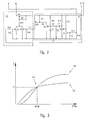
- Figure 3 of the drawings shows two typical graph of the current I of the battery, both in the case of star connection, and in the case of delta connection upon variation of the number of revolutions per minute, RPM, of the rotor 2 of the voltage generator 1.
- the graph ST shows the flow of I in the case of a star connection
- the graph TR shows the flow of I in the case of a delta connection. It can be seen that the current I, at low revolution numbers, below the threshold value RPM', assumes lower values when the phase windings are delta connected TR, compared to the star connection ST; the opposite occurs at revolution numbers higher than RPM'.
- Figure 3 also shows the point P1 relating to a revolution number corresponding to the threshold value RPM', for which the voltage generator 1 supplies a current I' for powering the battery 5 quantitatively independent of the type of connection of phase windings; point P is consequently the time at which occurs the change between the delta and star connection, and vice versa.
- Figure 4 shows the graph in respect to time of the voltage VB of the battery 5 in the event of the number of revolutions RPM of the rotor 2 being lower than RPM' of figure 3
- figure 5 shows the graph over time t of the voltage VB in the event of the number of revolutions RPM being higher than RPM'.
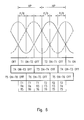
- figure 6 shows the procedure with which the electronic switches T1-T6, which allow the selective star and delta connections of the phase windings 3A, 3B and 3C of the voltage generator 1, are piloted in conduction (ON), or in interdiction (OFF), by the voltage regulator.
- a terminal of each of the three phase windings 3A, 3B and 3C of the generator 1 is connected to the positive terminal of the battery 5 by a pair of semi-bridge rectifiers 4.1, 4.2, and is selectively connectable to ground by a short-circuiting switch 6 controlled by the electronic control circuit 11.
- the voltage regulator comprises three switching devices 8 each consisting of a first and second thyristor T which have their respective anodes and cathodes connected in anti-parallel with one another, and connected to the terminals not short-circuitable to ground of two different phase windings; the control electrodes of the thyristors T of the three switching devices 8 are piloted separately by the electronic circuits 9 and 10 which carry out both the measurement of the voltage frequency of one phase of the generator 1, for example the frequencies of the phase winding 3.6, and the changing of the connection configuration.
- the switches 6 for short-circuiting to ground the phase windings are activated as soon as the battery rated value VR is exceeded; in addition, in order to decrease the current which flows in the phase windings of the generator, and in the switching devices 8, the short-circuiting switches 6 do not enter into conduction when the phase windings are delta connected, but only after the control circuit 10 has forced the star connection.
- a voltage regulator for permanent magnet generators is provided, with windings connection selectively configurable in two different conditions, of such kind as to supply the maximum current required to maintain the voltage VB for charging a battery constant, regardless of the requests for power thereby preventing, upon reaching the battery regulating voltage VR, excessive currents from flowing in the phase windings of the voltage generator 1 and in the switching devices 8 for changing the connection configuration.
Landscapes
- Engineering & Computer Science (AREA)
- Power Engineering (AREA)
- Control Of Eletrric Generators (AREA)
- Coils Of Transformers For General Uses (AREA)
Applications Claiming Priority (1)
| Application Number | Priority Date | Filing Date | Title |
|---|---|---|---|
| IT001432A ITMI20071432A1 (it) | 2007-07-17 | 2007-07-17 | Regolatore di tensione per magnetogeneratori a connessione configurabile degli avvolgimenti di fase |
Publications (3)
| Publication Number | Publication Date |
|---|---|
| EP2017941A2 true EP2017941A2 (fr) | 2009-01-21 |
| EP2017941A3 EP2017941A3 (fr) | 2011-11-23 |
| EP2017941B1 EP2017941B1 (fr) | 2015-08-05 |
Family
ID=39924914
Family Applications (1)
| Application Number | Title | Priority Date | Filing Date |
|---|---|---|---|
| EP08011115.6A Active EP2017941B1 (fr) | 2007-07-17 | 2008-06-19 | Régulateur de tension pour magnéto-génératrices avec connexion configurable des enroulements de phase |
Country Status (7)
| Country | Link |
|---|---|
| US (1) | US7948218B2 (fr) |
| EP (1) | EP2017941B1 (fr) |
| KR (1) | KR101105894B1 (fr) |
| CN (1) | CN101350534B (fr) |
| CA (1) | CA2635577C (fr) |
| IT (1) | ITMI20071432A1 (fr) |
| TW (1) | TWI404327B (fr) |
Cited By (1)
| Publication number | Priority date | Publication date | Assignee | Title |
|---|---|---|---|---|
| DE102017222826A1 (de) * | 2017-12-15 | 2019-06-19 | Robert Bosch Gmbh | Vorrichtung zur Laderegelung für einen elektrischen Speicher in einem Kraftfahrzeug |
Families Citing this family (8)
| Publication number | Priority date | Publication date | Assignee | Title |
|---|---|---|---|---|
| US8922165B2 (en) * | 2012-05-14 | 2014-12-30 | Freescale Semiconductor, Inc. | Cell balance configuration for pin count reduction |
| EP2728712A1 (fr) * | 2012-10-31 | 2014-05-07 | Openhydro IP Limited | Générateur de puissance pour turbine hydraulique |
| CN104836203A (zh) * | 2014-02-12 | 2015-08-12 | 北京佩特来电器有限公司 | 一种用于机动车的交流发电机及其自我保护方法 |
| FR3028108A1 (fr) | 2014-10-31 | 2016-05-06 | Sarkis Armoudian | Unite de production electrique autonome autoregulee fournissant un courant continu, et son utilisation dans une borne autonome d'alimentation electrique d'une antenne-relais. |
| US10644513B2 (en) | 2016-06-08 | 2020-05-05 | Hamilton Sundstrand Corporation | High voltage power generating system |
| JP6825961B2 (ja) * | 2017-03-30 | 2021-02-03 | 本田技研工業株式会社 | エンジン発電機 |
| US11424612B2 (en) | 2019-04-15 | 2022-08-23 | Ge Aviation Systems Llc | Method and apparatus for over voltage protection of a power system |
| CN114142777B (zh) * | 2021-12-02 | 2023-10-10 | 珠海格力电器股份有限公司 | 多相发电机的控制系统、方法及存储介质 |
Citations (1)
| Publication number | Priority date | Publication date | Assignee | Title |
|---|---|---|---|---|
| US7026794B1 (en) | 2004-02-06 | 2006-04-11 | Brp Us Inc. | Dynamically controlled switching alternator system |
Family Cites Families (46)
| Publication number | Priority date | Publication date | Assignee | Title |
|---|---|---|---|---|
| DE1763303A1 (de) * | 1968-05-02 | 1970-08-13 | Bosch Gmbh Robert | Spannungsregler fuer einen permanentmagnetisch erregten Wechselstromgenerator |
| BE795399A (fr) * | 1972-02-18 | 1973-05-29 | Jeumont Schneider | Systeme de commutation statique pour effectuer instantanement divers branchements de deux machines a courant continu |
| DE2426956A1 (de) * | 1974-06-04 | 1976-01-02 | Bosch Gmbh Robert | Wechselstromgenerator |
| US4045718A (en) * | 1975-04-02 | 1977-08-30 | Maremont Corporation | Multiple winding multiple voltage alternator electrical supply system |
| US4058759A (en) * | 1975-11-19 | 1977-11-15 | Xerox Corporation | Power supply for computer peripheral device |
| US4175249A (en) * | 1978-06-19 | 1979-11-20 | The United States Of America As Represented By The Administrator Of The National Aeronautics And Space Administration | Self-reconfiguring solar cell system |
| US4236050A (en) * | 1978-06-30 | 1980-11-25 | Mca Discovision, Inc. | System for recovering information from a movable information storage medium having a pilot signal with an aligned phase angle in adjacent tracks |
| US4313191A (en) * | 1978-06-30 | 1982-01-26 | Discovision Associates | Recording medium having a pilot signal with an aligned phase angle in adjacent tracks |
| US4374323A (en) * | 1978-06-30 | 1983-02-15 | Discovision Associates | Focusing apparatus for use in a system for recovering information from an optically-readable storage medium |
| US4353089A (en) * | 1978-06-30 | 1982-10-05 | Discovision Associates | Apparatus for correcting the time base of information recovered from a movable information storage medium |
| US4338557A (en) * | 1979-08-14 | 1982-07-06 | Wanlass Cravens Lamar | Variable speed electric machine having controlled magnetic flux density |
| US4339704A (en) * | 1980-07-07 | 1982-07-13 | General Electric Company | Series parallel transition for power supply |
| DE3041201A1 (de) * | 1980-11-03 | 1982-06-09 | Robert Bosch Gmbh, 7000 Stuttgart | Verfahren und vorrichtung zur besseren ausnutzung der stromabgabe, insbesondere von drehstormgeneratoren bei kraftfahrzeugen |
| FR2605471B1 (fr) * | 1986-05-23 | 1991-05-17 | Ducellier & Cie | Perfectionnement a un dispositif d'alimentation electrique en regime temporaire des circuits auxiliaires d'un vehicule automobile |
| US4780659A (en) * | 1987-04-01 | 1988-10-25 | Sundstrand Corporation | High-power, high-voltage direct current power source |
| US5276603A (en) * | 1990-05-03 | 1994-01-04 | Crown International, Inc. | Sixteen level power supply with asynchronous controller |
| CN2153898Y (zh) * | 1992-12-13 | 1994-01-19 | 王自 | 具有保护功能的车用永磁发电机 |
| JPH06334208A (ja) * | 1993-05-19 | 1994-12-02 | Nec Corp | 太陽発電装置 |
| US5859525A (en) * | 1993-09-24 | 1999-01-12 | Minks Engineering, Inc. | Alternator rectification, regulation, and control circuit |
| US5625276A (en) * | 1994-09-14 | 1997-04-29 | Coleman Powermate, Inc. | Controller for permanent magnet generator |
| JP3303015B2 (ja) * | 1995-02-01 | 2002-07-15 | いすゞ自動車株式会社 | 磁石式発電機の電圧制御装置 |
| DE19519298A1 (de) * | 1995-05-26 | 1996-11-28 | Bosch Gmbh Robert | Vorrichtung zur Spannungsversorgung mit zwei Ausgangsspannungen |
| KR0178158B1 (ko) * | 1995-11-16 | 1999-05-15 | 정몽원 | 차량용 교류발전기 |
| US5737694A (en) * | 1995-11-30 | 1998-04-07 | Scientific-Atlanta, Inc. | Highly stable frequency synthesizer loop with feedforward |
| US5723972A (en) * | 1995-12-29 | 1998-03-03 | Bartol; Luis E. | Fail-safe common control of multiple alternators electrically connected in tandem parallel for producing high current |
| US6066941A (en) * | 1998-07-10 | 2000-05-23 | Outboard Marine Corporation | Switching alternator system |
| JP2001197787A (ja) * | 1999-11-05 | 2001-07-19 | Mitsubishi Heavy Ind Ltd | カーエアコンシステム用発電機の電機子巻線切替方式 |
| US6912142B2 (en) * | 2000-01-24 | 2005-06-28 | Massachusetts Institute Of Technology | Alternator control circuit and related techniques |
| US20020089866A1 (en) * | 2000-01-24 | 2002-07-11 | Keim Thomas A. | Alternator control circuit and related techniques |
| US6239996B1 (en) * | 2000-01-24 | 2001-05-29 | Massachusetts Institute Of Technology | Dual output alternator system |
| US6366060B1 (en) * | 2000-08-10 | 2002-04-02 | Delphi Technologies, Inc. | Mosfet control circuit for dual winding alternator |
| JP4229013B2 (ja) * | 2003-09-01 | 2009-02-25 | 株式会社デンソー | 交流発電機 |
| JP3879736B2 (ja) * | 2003-12-19 | 2007-02-14 | 日産自動車株式会社 | 4輪駆動車両の駆動制御装置 |
| US6914342B1 (en) * | 2004-02-06 | 2005-07-05 | Bombardier Recreational Products Inc. | Engine control unit enablement system |
| ITMI20041026A1 (it) * | 2004-05-24 | 2004-08-24 | Ducati Energia Spa | Regolatore di tensione a power mos per la ricarica di batterie |
| JP4232693B2 (ja) * | 2004-06-08 | 2009-03-04 | 株式会社デンソー | 車両用発電制御システム |
| US7116080B2 (en) * | 2004-07-07 | 2006-10-03 | Visteon Global Technologies, Inc. | Alternator rectifier with coil-sensor controlled MOSFETs |
| US7053590B2 (en) * | 2004-08-24 | 2006-05-30 | Elliott Energy Systems, Inc. | Power generating system including a high-frequency alternator, a rectifier module, and an auxiliary power supply |
| KR100677277B1 (ko) * | 2005-05-11 | 2007-02-02 | 엘지전자 주식회사 | 무전극 램프 시스템 |
| CN1949655B (zh) * | 2005-10-10 | 2010-05-12 | 贺雷 | 电动-发电复用控制方法及其系统 |
| FR2893782B1 (fr) * | 2005-11-23 | 2010-09-10 | Leroy Somer Moteurs | Dispositif de production d electricite pour alternateur a vitesse variable |
| US7348764B2 (en) * | 2006-07-13 | 2008-03-25 | Ocean Power Technologies, Inc. | Coil switching of an electric generator |
| US7977842B2 (en) * | 2006-10-05 | 2011-07-12 | Lin Panchien | Adaptive winding system and control method for electric machines |
| TWM325238U (en) * | 2006-12-29 | 2008-01-11 | Universal Scient Ind Co Ltd | Voltage regulator and voltage regulating system |
| US8115433B2 (en) * | 2008-09-23 | 2012-02-14 | GM Global Technology Operations LLC | Electrical system for pulse-width modulated control of a power inverter using phase-shifted carrier signals and related operating methods |
| US8269434B2 (en) * | 2008-09-23 | 2012-09-18 | GM Global Technology Operations LLC | Electrical system using phase-shifted carrier signals and related operating methods |
-
2007
- 2007-07-17 IT IT001432A patent/ITMI20071432A1/it unknown
-
2008
- 2008-06-19 EP EP08011115.6A patent/EP2017941B1/fr active Active
- 2008-06-23 CA CA2635577A patent/CA2635577C/fr active Active
- 2008-06-24 TW TW097123437A patent/TWI404327B/zh not_active IP Right Cessation
- 2008-07-08 US US12/168,931 patent/US7948218B2/en active Active
- 2008-07-09 KR KR1020080066367A patent/KR101105894B1/ko not_active Expired - Fee Related
- 2008-07-16 CN CN2008101336387A patent/CN101350534B/zh not_active Expired - Fee Related
Patent Citations (1)
| Publication number | Priority date | Publication date | Assignee | Title |
|---|---|---|---|---|
| US7026794B1 (en) | 2004-02-06 | 2006-04-11 | Brp Us Inc. | Dynamically controlled switching alternator system |
Cited By (1)
| Publication number | Priority date | Publication date | Assignee | Title |
|---|---|---|---|---|
| DE102017222826A1 (de) * | 2017-12-15 | 2019-06-19 | Robert Bosch Gmbh | Vorrichtung zur Laderegelung für einen elektrischen Speicher in einem Kraftfahrzeug |
Also Published As
| Publication number | Publication date |
|---|---|
| ITMI20071432A1 (it) | 2009-01-18 |
| CN101350534B (zh) | 2012-07-04 |
| CN101350534A (zh) | 2009-01-21 |
| CA2635577C (fr) | 2014-07-15 |
| CA2635577A1 (fr) | 2009-01-17 |
| US7948218B2 (en) | 2011-05-24 |
| TWI404327B (zh) | 2013-08-01 |
| EP2017941A3 (fr) | 2011-11-23 |
| TW200922112A (en) | 2009-05-16 |
| KR20090008129A (ko) | 2009-01-21 |
| US20090021224A1 (en) | 2009-01-22 |
| EP2017941B1 (fr) | 2015-08-05 |
| KR101105894B1 (ko) | 2012-01-17 |
Similar Documents
| Publication | Publication Date | Title |
|---|---|---|
| EP2017941B1 (fr) | Régulateur de tension pour magnéto-génératrices avec connexion configurable des enroulements de phase | |
| US6034511A (en) | Light weight rotor and stator with multiple coil windings in thermal contact | |
| JP3794391B2 (ja) | 発電装置 | |
| US7102331B2 (en) | Generator with dual cycloconverter for 120/240 VAC operation | |
| JPS62501188A (ja) | 可変速度一定周波数 | |
| JPH05252747A (ja) | 電圧調整装置 | |
| US9917544B2 (en) | Method and power converter unit for operating a generator | |
| JP2001231180A (ja) | バッテリ充電装置 | |
| US10763675B2 (en) | Power generator system | |
| US6066941A (en) | Switching alternator system | |
| US20140210426A1 (en) | Power generation control unit determining maximum excitation current of power generator mounted on vehicle | |
| JP4370068B2 (ja) | 特に路上走行車輛用の三相回路網による発電装置 | |
| EP2109213B1 (fr) | Procédé et système de contrôle pour l'alimentation sélective d'une charge électrique par un générateur électro-magnétique | |
| JP6695250B2 (ja) | 界磁巻線型同期電動機 | |
| EP2068421B1 (fr) | Régulateur de tension et ensemble générateur pour charger des batteries | |
| US20070285954A1 (en) | Regulator Control Circuit and Method | |
| JP3681050B2 (ja) | 磁石発電機を用いた電源装置 | |
| US6906480B2 (en) | Regulator control circuit and method | |
| Allen | Brushless excitation systems for synchronous machines | |
| JP2876738B2 (ja) | 直並列切換回転電機 | |
| JP3577174B2 (ja) | バッテリ充電装置 | |
| JPS63316645A (ja) | 車両用交流発電機の発電制御装置 | |
| JPS58154336A (ja) | 充電発電機制御装置 |
Legal Events
| Date | Code | Title | Description |
|---|---|---|---|
| PUAI | Public reference made under article 153(3) epc to a published international application that has entered the european phase |
Free format text: ORIGINAL CODE: 0009012 |
|
| AK | Designated contracting states |
Kind code of ref document: A2 Designated state(s): AT BE BG CH CY CZ DE DK EE ES FI FR GB GR HR HU IE IS IT LI LT LU LV MC MT NL NO PL PT RO SE SI SK TR |
|
| AX | Request for extension of the european patent |
Extension state: AL BA MK RS |
|
| PUAL | Search report despatched |
Free format text: ORIGINAL CODE: 0009013 |
|
| AK | Designated contracting states |
Kind code of ref document: A3 Designated state(s): AT BE BG CH CY CZ DE DK EE ES FI FR GB GR HR HU IE IS IT LI LT LU LV MC MT NL NO PL PT RO SE SI SK TR |
|
| AX | Request for extension of the european patent |
Extension state: AL BA MK RS |
|
| RIC1 | Information provided on ipc code assigned before grant |
Ipc: H02J 7/14 20060101AFI20111019BHEP Ipc: H02P 9/48 20060101ALI20111019BHEP |
|
| 17P | Request for examination filed |
Effective date: 20120522 |
|
| AKX | Designation fees paid |
Designated state(s): AT BE BG CH CY CZ DE DK EE ES FI FR GB GR HR HU IE IS IT LI LT LU LV MC MT NL NO PL PT RO SE SI SK TR |
|
| GRAP | Despatch of communication of intention to grant a patent |
Free format text: ORIGINAL CODE: EPIDOSNIGR1 |
|
| INTG | Intention to grant announced |
Effective date: 20150205 |
|
| GRAS | Grant fee paid |
Free format text: ORIGINAL CODE: EPIDOSNIGR3 |
|
| GRAA | (expected) grant |
Free format text: ORIGINAL CODE: 0009210 |
|
| AK | Designated contracting states |
Kind code of ref document: B1 Designated state(s): AT BE BG CH CY CZ DE DK EE ES FI FR GB GR HR HU IE IS IT LI LT LU LV MC MT NL NO PL PT RO SE SI SK TR |
|
| REG | Reference to a national code |
Ref country code: GB Ref legal event code: FG4D |
|
| REG | Reference to a national code |
Ref country code: CH Ref legal event code: EP |
|
| REG | Reference to a national code |
Ref country code: AT Ref legal event code: REF Ref document number: 741179 Country of ref document: AT Kind code of ref document: T Effective date: 20150815 |
|
| REG | Reference to a national code |
Ref country code: IE Ref legal event code: FG4D |
|
| REG | Reference to a national code |
Ref country code: DE Ref legal event code: R096 Ref document number: 602008039351 Country of ref document: DE |
|
| REG | Reference to a national code |
Ref country code: LT Ref legal event code: MG4D |
|
| REG | Reference to a national code |
Ref country code: NL Ref legal event code: MP Effective date: 20150805 |
|
| PG25 | Lapsed in a contracting state [announced via postgrant information from national office to epo] |
Ref country code: LT Free format text: LAPSE BECAUSE OF FAILURE TO SUBMIT A TRANSLATION OF THE DESCRIPTION OR TO PAY THE FEE WITHIN THE PRESCRIBED TIME-LIMIT Effective date: 20150805 Ref country code: GR Free format text: LAPSE BECAUSE OF FAILURE TO SUBMIT A TRANSLATION OF THE DESCRIPTION OR TO PAY THE FEE WITHIN THE PRESCRIBED TIME-LIMIT Effective date: 20151106 Ref country code: NO Free format text: LAPSE BECAUSE OF FAILURE TO SUBMIT A TRANSLATION OF THE DESCRIPTION OR TO PAY THE FEE WITHIN THE PRESCRIBED TIME-LIMIT Effective date: 20151105 Ref country code: LV Free format text: LAPSE BECAUSE OF FAILURE TO SUBMIT A TRANSLATION OF THE DESCRIPTION OR TO PAY THE FEE WITHIN THE PRESCRIBED TIME-LIMIT Effective date: 20150805 |
|
| PG25 | Lapsed in a contracting state [announced via postgrant information from national office to epo] |
Ref country code: PT Free format text: LAPSE BECAUSE OF FAILURE TO SUBMIT A TRANSLATION OF THE DESCRIPTION OR TO PAY THE FEE WITHIN THE PRESCRIBED TIME-LIMIT Effective date: 20151207 Ref country code: PL Free format text: LAPSE BECAUSE OF FAILURE TO SUBMIT A TRANSLATION OF THE DESCRIPTION OR TO PAY THE FEE WITHIN THE PRESCRIBED TIME-LIMIT Effective date: 20150805 Ref country code: SE Free format text: LAPSE BECAUSE OF FAILURE TO SUBMIT A TRANSLATION OF THE DESCRIPTION OR TO PAY THE FEE WITHIN THE PRESCRIBED TIME-LIMIT Effective date: 20150805 Ref country code: ES Free format text: LAPSE BECAUSE OF FAILURE TO SUBMIT A TRANSLATION OF THE DESCRIPTION OR TO PAY THE FEE WITHIN THE PRESCRIBED TIME-LIMIT Effective date: 20150805 Ref country code: IS Free format text: LAPSE BECAUSE OF FAILURE TO SUBMIT A TRANSLATION OF THE DESCRIPTION OR TO PAY THE FEE WITHIN THE PRESCRIBED TIME-LIMIT Effective date: 20151205 Ref country code: HR Free format text: LAPSE BECAUSE OF FAILURE TO SUBMIT A TRANSLATION OF THE DESCRIPTION OR TO PAY THE FEE WITHIN THE PRESCRIBED TIME-LIMIT Effective date: 20150805 |
|
| REG | Reference to a national code |
Ref country code: AT Ref legal event code: UEP Ref document number: 741179 Country of ref document: AT Kind code of ref document: T Effective date: 20150805 |
|
| PG25 | Lapsed in a contracting state [announced via postgrant information from national office to epo] |
Ref country code: NL Free format text: LAPSE BECAUSE OF FAILURE TO SUBMIT A TRANSLATION OF THE DESCRIPTION OR TO PAY THE FEE WITHIN THE PRESCRIBED TIME-LIMIT Effective date: 20150805 |
|
| PG25 | Lapsed in a contracting state [announced via postgrant information from national office to epo] |
Ref country code: EE Free format text: LAPSE BECAUSE OF FAILURE TO SUBMIT A TRANSLATION OF THE DESCRIPTION OR TO PAY THE FEE WITHIN THE PRESCRIBED TIME-LIMIT Effective date: 20150805 Ref country code: CZ Free format text: LAPSE BECAUSE OF FAILURE TO SUBMIT A TRANSLATION OF THE DESCRIPTION OR TO PAY THE FEE WITHIN THE PRESCRIBED TIME-LIMIT Effective date: 20150805 Ref country code: DK Free format text: LAPSE BECAUSE OF FAILURE TO SUBMIT A TRANSLATION OF THE DESCRIPTION OR TO PAY THE FEE WITHIN THE PRESCRIBED TIME-LIMIT Effective date: 20150805 Ref country code: SK Free format text: LAPSE BECAUSE OF FAILURE TO SUBMIT A TRANSLATION OF THE DESCRIPTION OR TO PAY THE FEE WITHIN THE PRESCRIBED TIME-LIMIT Effective date: 20150805 |
|
| REG | Reference to a national code |
Ref country code: DE Ref legal event code: R097 Ref document number: 602008039351 Country of ref document: DE |
|
| PG25 | Lapsed in a contracting state [announced via postgrant information from national office to epo] |
Ref country code: RO Free format text: LAPSE BECAUSE OF FAILURE TO SUBMIT A TRANSLATION OF THE DESCRIPTION OR TO PAY THE FEE WITHIN THE PRESCRIBED TIME-LIMIT Effective date: 20150805 |
|
| PLBE | No opposition filed within time limit |
Free format text: ORIGINAL CODE: 0009261 |
|
| STAA | Information on the status of an ep patent application or granted ep patent |
Free format text: STATUS: NO OPPOSITION FILED WITHIN TIME LIMIT |
|
| 26N | No opposition filed |
Effective date: 20160509 |
|
| PG25 | Lapsed in a contracting state [announced via postgrant information from national office to epo] |
Ref country code: SI Free format text: LAPSE BECAUSE OF FAILURE TO SUBMIT A TRANSLATION OF THE DESCRIPTION OR TO PAY THE FEE WITHIN THE PRESCRIBED TIME-LIMIT Effective date: 20150805 |
|
| PG25 | Lapsed in a contracting state [announced via postgrant information from national office to epo] |
Ref country code: BE Free format text: LAPSE BECAUSE OF FAILURE TO SUBMIT A TRANSLATION OF THE DESCRIPTION OR TO PAY THE FEE WITHIN THE PRESCRIBED TIME-LIMIT Effective date: 20150805 |
|
| REG | Reference to a national code |
Ref country code: DE Ref legal event code: R119 Ref document number: 602008039351 Country of ref document: DE |
|
| PG25 | Lapsed in a contracting state [announced via postgrant information from national office to epo] |
Ref country code: MC Free format text: LAPSE BECAUSE OF FAILURE TO SUBMIT A TRANSLATION OF THE DESCRIPTION OR TO PAY THE FEE WITHIN THE PRESCRIBED TIME-LIMIT Effective date: 20150805 |
|
| REG | Reference to a national code |
Ref country code: CH Ref legal event code: PL |
|
| GBPC | Gb: european patent ceased through non-payment of renewal fee |
Effective date: 20160619 |
|
| REG | Reference to a national code |
Ref country code: IE Ref legal event code: MM4A |
|
| REG | Reference to a national code |
Ref country code: FR Ref legal event code: ST Effective date: 20170228 |
|
| PG25 | Lapsed in a contracting state [announced via postgrant information from national office to epo] |
Ref country code: FR Free format text: LAPSE BECAUSE OF NON-PAYMENT OF DUE FEES Effective date: 20160630 Ref country code: CH Free format text: LAPSE BECAUSE OF NON-PAYMENT OF DUE FEES Effective date: 20160630 Ref country code: LI Free format text: LAPSE BECAUSE OF NON-PAYMENT OF DUE FEES Effective date: 20160630 Ref country code: DE Free format text: LAPSE BECAUSE OF NON-PAYMENT OF DUE FEES Effective date: 20170103 |
|
| PG25 | Lapsed in a contracting state [announced via postgrant information from national office to epo] |
Ref country code: IE Free format text: LAPSE BECAUSE OF NON-PAYMENT OF DUE FEES Effective date: 20160619 Ref country code: GB Free format text: LAPSE BECAUSE OF NON-PAYMENT OF DUE FEES Effective date: 20160619 |
|
| PG25 | Lapsed in a contracting state [announced via postgrant information from national office to epo] |
Ref country code: CY Free format text: LAPSE BECAUSE OF FAILURE TO SUBMIT A TRANSLATION OF THE DESCRIPTION OR TO PAY THE FEE WITHIN THE PRESCRIBED TIME-LIMIT Effective date: 20150805 Ref country code: HU Free format text: LAPSE BECAUSE OF FAILURE TO SUBMIT A TRANSLATION OF THE DESCRIPTION OR TO PAY THE FEE WITHIN THE PRESCRIBED TIME-LIMIT; INVALID AB INITIO Effective date: 20080619 |
|
| PG25 | Lapsed in a contracting state [announced via postgrant information from national office to epo] |
Ref country code: MT Free format text: LAPSE BECAUSE OF NON-PAYMENT OF DUE FEES Effective date: 20160630 Ref country code: TR Free format text: LAPSE BECAUSE OF FAILURE TO SUBMIT A TRANSLATION OF THE DESCRIPTION OR TO PAY THE FEE WITHIN THE PRESCRIBED TIME-LIMIT Effective date: 20150805 Ref country code: LU Free format text: LAPSE BECAUSE OF NON-PAYMENT OF DUE FEES Effective date: 20160619 |
|
| PG25 | Lapsed in a contracting state [announced via postgrant information from national office to epo] |
Ref country code: BG Free format text: LAPSE BECAUSE OF FAILURE TO SUBMIT A TRANSLATION OF THE DESCRIPTION OR TO PAY THE FEE WITHIN THE PRESCRIBED TIME-LIMIT Effective date: 20150805 |
|
| P01 | Opt-out of the competence of the unified patent court (upc) registered |
Effective date: 20230527 |
|
| PGFP | Annual fee paid to national office [announced via postgrant information from national office to epo] |
Ref country code: FI Payment date: 20250625 Year of fee payment: 18 |
|
| PGFP | Annual fee paid to national office [announced via postgrant information from national office to epo] |
Ref country code: AT Payment date: 20250603 Year of fee payment: 18 |
|
| PGFP | Annual fee paid to national office [announced via postgrant information from national office to epo] |
Ref country code: IT Payment date: 20250618 Year of fee payment: 18 |