EP2017977B1 - System und Verfahren zur Steuerung von Intermodulationsinterferenz - Google Patents
System und Verfahren zur Steuerung von Intermodulationsinterferenz Download PDFInfo
- Publication number
- EP2017977B1 EP2017977B1 EP08160815.0A EP08160815A EP2017977B1 EP 2017977 B1 EP2017977 B1 EP 2017977B1 EP 08160815 A EP08160815 A EP 08160815A EP 2017977 B1 EP2017977 B1 EP 2017977B1
- Authority
- EP
- European Patent Office
- Prior art keywords
- transmitters
- signal
- processing unit
- receive frequency
- product
- Prior art date
- Legal status (The legal status is an assumption and is not a legal conclusion. Google has not performed a legal analysis and makes no representation as to the accuracy of the status listed.)
- Not-in-force
Links
- 238000000034 method Methods 0.000 title claims description 36
- 238000012545 processing Methods 0.000 claims description 52
- 230000005540 biological transmission Effects 0.000 claims description 40
- 238000001228 spectrum Methods 0.000 claims description 21
- 230000000694 effects Effects 0.000 claims description 16
- 230000000644 propagated effect Effects 0.000 claims description 8
- 230000000977 initiatory effect Effects 0.000 claims 5
- 238000004891 communication Methods 0.000 description 12
- 230000003111 delayed effect Effects 0.000 description 4
- 238000001914 filtration Methods 0.000 description 3
- 239000002131 composite material Substances 0.000 description 2
- 230000001419 dependent effect Effects 0.000 description 2
- 238000010586 diagram Methods 0.000 description 2
- 238000005516 engineering process Methods 0.000 description 2
- 230000008054 signal transmission Effects 0.000 description 2
- 238000012360 testing method Methods 0.000 description 2
- 230000006978 adaptation Effects 0.000 description 1
- 230000002411 adverse Effects 0.000 description 1
- 230000032683 aging Effects 0.000 description 1
- 230000003321 amplification Effects 0.000 description 1
- 238000005260 corrosion Methods 0.000 description 1
- 230000007797 corrosion Effects 0.000 description 1
- 230000001934 delay Effects 0.000 description 1
- 230000018109 developmental process Effects 0.000 description 1
- 230000008030 elimination Effects 0.000 description 1
- 238000003379 elimination reaction Methods 0.000 description 1
- 238000009434 installation Methods 0.000 description 1
- 229910052741 iridium Inorganic materials 0.000 description 1
- GKOZUEZYRPOHIO-UHFFFAOYSA-N iridium atom Chemical compound [Ir] GKOZUEZYRPOHIO-UHFFFAOYSA-N 0.000 description 1
- 238000003199 nucleic acid amplification method Methods 0.000 description 1
- 230000003287 optical effect Effects 0.000 description 1
- 230000002265 prevention Effects 0.000 description 1
- 238000011897 real-time detection Methods 0.000 description 1
- 239000004065 semiconductor Substances 0.000 description 1
- 238000013519 translation Methods 0.000 description 1
Images


Classifications
-
- H—ELECTRICITY
- H04—ELECTRIC COMMUNICATION TECHNIQUE
- H04B—TRANSMISSION
- H04B7/00—Radio transmission systems, i.e. using radiation field
- H04B7/14—Relay systems
- H04B7/15—Active relay systems
- H04B7/185—Space-based or airborne stations; Stations for satellite systems
- H04B7/1851—Systems using a satellite or space-based relay
- H04B7/18517—Transmission equipment in earth stations
-
- H—ELECTRICITY
- H04—ELECTRIC COMMUNICATION TECHNIQUE
- H04B—TRANSMISSION
- H04B15/00—Suppression or limitation of noise or interference
- H04B15/02—Reducing interference from electric apparatus by means located at or near the interfering apparatus
Definitions
- Intermodulation is caused by non-linearities in the radio frequency (RF) path between the transmitter and the receiver in a communication system. These non-linearities may exist within the transmitter amplification and filtering chain, at the transmit antenna, along the propagation path between the transmitter and receiver, within the receiver antenna, or within the receiver downconversion chain.
- g k are the voltage gain coefficients corresponding to the k- th order non linearity.
- g 1 is the nominal linear voltage gain of the device.
- Intermodulation distortion occurs when two or more modulated or unmodulated RF carrier signals interact to create undesired signals on frequencies other than the original carrier signals.
- the value of k is odd.
- the value of k is referred to as the order of the intermodulation product.
- Inmarsat assigned channels to aeronautical services of any type that were specifically selected to assure that low-order intermodulation products from multi-carrier radios did not fall in the frequency bands of the receiver. Inmarsat has determined that continuing to provide this frequency management function has an adverse effect on its ability to satisfy the communication demands of its users. Therefore, Inmarsat has determined that it will no longer attempt to manage frequency assignments after 2009.
- legacy equipment provides transmit-path filtering to protect these bands.
- new Swift Broadband and some classes of Swift 64 channels will not benefit from such frequency management.
- Inmarsat has initiated a development program to produce a new, high-technology transmit-path filter that could be used to provide additional protection in new installations providing Swift Broadband and Swift 64.
- Such filtering does not, and can not protect any of the frequency bands mentioned above from intermodulation products generated after the filter. Therefore, sources of intermodulation products after the filter, such as transmit antenna intermodulation, continue to be of concern.
- EP1187435 discloses a related method of controlling intermodulation interference in a system including at least two transmitters and a receiver.
- the present invention provides a method as defined in claim 1.
- the method may include the features of any one or more of dependent claims 2 to 6.
- the present invention also provides a radio as defined in claim 7.
- the radio may include the features of any one or more of dependent claims 8 to 10.
- a method of controlling intermodulation (IM) interference comprises determining if an IM product spectrum overlaps the spectrum of an assigned receive frequency and determining when transmissions from at least two transmitters are to overlap in time. If the IM product spectrum overlaps the assigned receive frequency spectrum, it is determined if a signal is being propagated on the receive frequency when the transmissions from the at least two transmitters are to overlap in time. If a signal is not being propagated on the receive frequency, the at least two transmitters are allowed to transmit the overlapping transmissions; and if a signal is being propagated on the receive frequency, control steps are initiated to reduce the effects of IM interference.
- IM intermodulation
- Embodiments of the present invention enable a multi-carrier radio to reduce the effects of intermodulation interference.
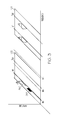
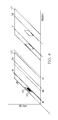
- embodiments of the present invention enable a processing unit to selectively take steps to reduce the effects of intermodulation interference when necessary. That is, in some embodiments, the processing unit only takes control steps when an intermodulation product actually poses a risk to proper reception of signals. Therefore, processing time and power are conserved when intermodulation products are either not generated or do not otherwise interfere with proper reception of signals. It should be noted that, for simplicity, only the frequency offsets given by the equation in page 1 line 19 are illustrated in Figures 2 , 3 , and 4 . That is, no bandwidth expansion effects are illustrated.
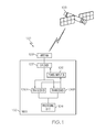
- FIG. 1 is a block diagram of a system 100 according to one embodiment of the present invention.
- System 100 includes a radio 102 in communication with satellite 108.
- Radio 102 is located on an aircraft in this embodiment.
- Radio 102 can be used on sea craft or any other appropriate vehicle or stationary system.
- Radio 102 is a multi-carrier transceiver radio which includes a processing unit 104 and at least two transceivers 106A and 106B. Although only two transceivers 106A and 106B are shown in this example, it is to be understood that any appropriate number of transceivers can be used in other embodiments.
- physically separate transmitters and receivers can be used in place of one or both transceivers 106A and 106B in other embodiments.
- the modulated outputs of transceivers 106A and 106B are combined in a single power amplifier 105.
- a diplexer filter 107 is used to filter the composite transmitted waveform consisting of the multiplicity of desired signals (two in this example) and any intermodulation products produced by the amplifier 105.
- the diplexer filter 107 also separates the intended transmitted signal from the desired received signals. However, filter 107 may be ineffective in providing sufficient protection against the transmitted intermodulation products.
- the composite transmitted signal is passed through an antenna 109 to the satellite 108.
- the desired received signal (or signals) are received through the antenna 109, passed to the diplexer 107, and thence to the receive ports of transcievers 106A and 106B.
- radio 102 and satellite 108 are described in relation to Inmarsat data service communications (such as Inmarsat-Aero H, Inmarsat-Aero H+, Inmarsat Aero I" etc.), embodiments of the present invention are not to be so limited.
- the system and method described herein can be implemented in a system using other communication protocols susceptible to intermodulation interference, as well as a system that desires to eliminate intermodulation to an independent service in closely proximate spectrum.
- Transceivers 106A and 106B each transmit a signal to satellite 108 on an assigned transmit frequency. Similarly, each of transceivers 106A and 106B receive a signal from satellite 108 over an assigned receive frequency.
- Fig. 2 depicts a graph showing exemplary transmit and receive frequencies for transceivers 106A and 106B.
- transceiver 106A transmits on transmit frequency f AT and transceiver 106B transmits on transmit frequency f BT each in transmit frequency band 101.
- transmit frequency band 101 comprises the frequencies 1626.5 Mhz - 1660.5 Mhz.
- transceiver 106A receives signals on receive frequency f AR and transceiver 106B receives signals on receiver frequency f BR .
- receive band 103 comprises the frequencies 1525 Mhz - 1559 Mhz.
- intermodulation frequency IM7 falls on the receive frequency f AR corresponding to transceiver 106A.
- Processing unit 104 is configured to control the transmission of signals via transceivers 106A and 106B in order to limit the effects of intermodulation distortion.
- a transmit schedule such as time division multiple access (TDMA)
- TDMA time division multiple access
- Each transceiver 106A and 106B has its own independent transmit schedule since each is transmitting on a separate frequency.
- Processing unit 104 analyzes each of the transmit schedules to determine when the transceivers 106A and 106B are scheduled transmission times that overlap.
- a transmit schedule is not used and each transceiver 106A and 106B transmits once it has data ready to transmit and its respective channel is clear.
- processing unit 104 controls when each of transceivers 106A and 106B is allowed to transmit based in part on the activity of the other transceiver. For example, when transceiver 106A is ready to transmit, processing unit 104 determines if the transceiver 106B is also ready to transmit or is already transmitting prior to allowing transceiver 106A to transmit. If transceiver 106B is not transmitting or is not ready to transmit, processing unit 104 allows transmission from transceiver 106A to proceed.
- processing unit 104 determines if a signal is being received on a receive frequency which is potentially affected by intermodulation products, such as frequency f AR in Fig. 2 . For example, if the receive signals are sent to radio 102 on a set time schedule, processing unit 104 analyzes the time schedule for the receive frequency in question to determine if a receive signal is scheduled to be received. In other embodiments, processing unit 104 causes the transceiver associated with the receive frequency to listen for a set period of time to determine if a signal is being received on the receive frequency.
- processing unit 104 causes one of transceivers 106A and 106B to delay transmitting its signal. For example, in some embodiments, processing unit 104 causes the transceiver with the lower priority signal to delay transmission of the signal. The delayed signal is then transmitted at a later time (in the next available time slot, for example). If both signals have the same priority and are intended to begin transmission at the same moment, the signal with the longer transmit time is delayed, in some embodiments. Delaying the signal with the longer transmit time results in shorter delays. In other embodiments, when both signals have the same priority, one signal is chosen at random to be delayed. However, if one signal is already being transmitted, the "first to transmit" is allowed to continue and the "second to transmit” is delayed regardless of the priority of the respective signals.
- processing unit 104 instructs transceiver 106A to drop the signal being received.
- the determination to drop a signal being received or which transceiver to delay is based, in some embodiments, on the international and national standards for priority, precedence, and preemption of safety communications known to one of ordinary skill in the art. For example, if the signals to be transmitted over each of transceivers 106A and 106B are time critical safety communications, processing unit 104 allows the signals to be transmitted and drops the signal being received.
- processing unit 104 is configured, in some embodiments, to modify the strength of signals transmitted from one or both of transceivers 106A and 106B to control the effects of intermodulation interference.
- processing unit 104 is configured to cause transceivers 106A and 106B to intentionally generate and measure the amplitude or power of intermodulation products falling within the receive band.
- the intentional intermodulation products can be generated and measured as part of system self-test actions. Such tests establish the intermodulation performance of the installed equipment, including any aging or corrosion effects.
- Processing unit 104 then compares the measured amplitude of intermodulation products with a threshold. If the amplitude is below the threshold, the intermodulation product will not cause interference with received signals.
- the transmission power (signal strength) is set by the communications protocol itself and can not be independently adjusted. In such embodiments, individual adjustment of the signal strength is not an option.
- Processing unit 104 includes or functions with software programs, firmware or other computer readable instructions for carrying out various methods, process tasks, calculations, and control functions, used in controlling intermodulation interference. These instructions are typically tangibly embodied on any appropriate medium used for storage of computer readable instructions or data structures. Such computer readable media includes any available media that can be accessed by a general purpose or special purpose computer or processing unit, or any programmable logic device.
- Suitable computer readable media comprise, for example, non-volatile memory devices including semiconductor memory devices such as EPROM, EEPROM, or flash memory devices; magnetic disks such as internal hard disks or removable disks (e.g., floppy disks); magnetooptical disks; CDs, DVDs, or other optical storage disks; nonvolatile ROM, RAM, and other like media. Any of the foregoing may be supplemented by, or incorporated in, specially-designed application-specific integrated circuits (ASICs).
- ASICs application-specific integrated circuits
- FIG. 5 is a flow chart showing a method 500 of controlling intermodulation interference according to one embodiment of the present invention.
- Method 500 can be implemented in computer readable media used by a processing unit such as processing unit 104 described above.
- the processing unit determines if there are two or more transmitters (such as transceivers 106A and 106B) in the radio such as radio 102. If only one transmitter is present, method 500 ends at 514.
- transmitters such as transceivers 106A and 106B
- method 500 continues at 504 where the processing unit determines if an intermodulation (IM) product frequency falls on one of the assigned receive frequencies.
- IM product frequencies and appropriate spectra can be calculated using equations known to one of ordinary skill in the art.
- the IM product frequencies for varying combinations of transmission frequencies can be stored in a look-up table and retrieved based on the assigned transmission frequencies. If none of the intermodulation product frequencies is such that the intermodulation product spectrum overlaps the desired signal spectrum on one of the assigned receive frequencies, method 500 ends at 514.
- the check at 504 also avoids unnecessary processing since interference will not occur if the intermodulation product spectra does not overlap the desired signal spectrum on any associated receive frequencies.
- the intermodulation products may be produced but they will not cause interference so no action needs to be taken.
- the processing unit flags the frequency for real-time detection and method 500 continues at 506 where the processing unit determines if the amplitude of the intermodulation product is greater than a predetermined threshold.
- the amplitude of the intermodulation product is determined by intentionally generating intermodulation products and measuring the amplitude of the IM product on the flagged frequencies.
- the threshold is determined such that an IM amplitude below the threshold will not interfere with a received signal and an IM amplitude equal to or greater than the threshold will interfere with a received signal. Therefore, if the IM amplitude is lower than the threshold, method 500 ends at 514. If the IM amplitude is equal to or greater than the threshold, method 500 continues at 508.
- the processing unit determines when two transmitters are transmitting simultaneously.
- the term "simultaneously" is defined as overlapping in time but not necessarily starting and ending at the same moment in time.
- the processing unit determines when transmissions from at least two transmitters are to overlap in time even if the transmissions do not start and end at the same time.
- the processing unit analyzes a transmit schedule for each transmitter to determine when transmissions from the two transmitters are scheduled to overlap. For example, each time a transmitter is ready to transmit the processing unit analyzes the transmit schedule to determine if the transmission is going to overlap a transmission from the other transmitter. In other embodiments, transmit schedules are not used. In such embodiments, each time one of the two transmitters is ready to transmit ,the processing unit determines, before permitting the transmission to proceed, if the other transmitter is already transmitting.
- method 500 ends at 514. However, if transmissions from the two transmitters are going to overlap, the processing unit determines if a signal is being received on the flagged receive frequency at 510. In one embodiment, the processing unit determines if a signal is being received by listening on the flagged frequency for a predetermined amount of time similar to carrier sense multiple access (CSMA) techniques known to one of skill in the art. If no signal is being received on the flagged receive frequency, the IM product will not cause interference. Hence, method 500 ends at 514 if no signal is being received.
- CSMA carrier sense multiple access
- Control steps to minimize the effects of intermodulation interference include, but are not limited to, delaying transmission from one of the two transmitters, dropping the signal being received, and adjusting the power of the transmission from one or both of the transmitters to reduce the amplitude of the IM product below the pre-determined threshold.
- the processing unit determines which control steps to initiate based, at least in part, on the international and national standards for priority, precedence, and preemption. For example, if each signal being transmitted from the two transmitters is critical or has a high priority, the processing unit can determine to allow a lower priority receive signal to be dropped. However, in other circumstances, it is not desirable to allow the receive signal to be dropped. In such circumstances, the processing unit can determine to delay transmission from the transmitter with the lower priority signal until the transmitters next scheduled transmission slot.
- method 500 is discussed in relation to two transmitters transmitting simultaneously, it is to be understood that method 500 can be adapted for use with three or more transmitters transmitting overlapping transmissions.
- the processing unit can calculate the possible IM product frequencies based on all the possible combinations of transmit frequencies and then check the corresponding receive frequency when each combination of transmit frequencies are to overlap in time.
- method 500 is simplified by eliminating some decision steps, such as steps 504, 506, or 510, and passing directly to the associated "YES" path. Such simplifications might be appropriate for radio designs with advanced hardware performance that may be developed with future technology. The efficiency of the method 500 will be affected with each such elimination. For example, significant benefit can still be obtained if the step 510 is eliminated, although at the cost of occasionally delaying a transmitted signal when no received signal were present.
- the method 500 may also be applied to protect either transmit or receive signals in well-defined signals in bands closely proximate to the Inmarsat transmit band. Such bands could include the bands used by Iridium (receive at 1616-1626.5 MHz), Globalstar (transmit 1610-1621.5 MHz), or GPS L1 (receive 1565-1585 MHz).
- Iridium transmit at 1616-1626.5 MHz
- Globalstar transmit 1610-1621.5 MHz
- GPS L1 receiver 1565-1585 MHz
- a much simplified version of method 500, consisting of steps 504 and 512 can be used for protection of GPS and GLONASS signals.
Landscapes
- Engineering & Computer Science (AREA)
- Computer Networks & Wireless Communication (AREA)
- Signal Processing (AREA)
- Physics & Mathematics (AREA)
- Astronomy & Astrophysics (AREA)
- Aviation & Aerospace Engineering (AREA)
- General Physics & Mathematics (AREA)
- Mobile Radio Communication Systems (AREA)
- Noise Elimination (AREA)
Claims (10)
- Verfahren (500) zum Steuern von Intermodulations-(IM-) Interferenz, wobei das Verfahren aufweist:Bestimmen, wann Sendungen von zumindest zwei Sendern zeitlich überlappen werden (508), wobei jedem der zumindest zwei Sender eine separate Sendefrequenz zugeordnet ist; unddadurch gekennzeichnet, dass, wenn Sendungen von den zumindest zwei Sendern zeitlich überlappen werden (512):Bestimmen, ob ein IM-Produktspektrum, das durch die zumindest zwei Sender erzeugt wird, das Spektrum einer zugeordneten Empfangsfrequenz überlappt (504);wenn das IM-Produktspektrum das zugeordnete Empfangsfrequenzspektrum überlappt, Bestimmen, ob ein Signal auf der Empfangsfrequenz läuft, wenn die Sendungen von den zumindest zwei Sendern zeitlich überlappen werden (510);wenn kein Signal auf der Empfangsfrequenz läuft, Zulassen, dass die zumindest zwei Sender die überlappenden Sendungen senden (514); undwenn ein Signal auf der Empfangsfrequenz läuft,Einleiten von Steuerungsschritten zur Verringerungen der Wirkungen einer IM-Interferenz (512).
- Verfahren (500) nach Anspruch 1, wobei das Einleiten von Steuerungsschritten zumindest eines der Folgenden enthält:Verzögern einer Sendung von einem der zumindest zwei Sender (512);Einstellen der Sendeleistung von zumindest einem der zumindest zwei Sender (512); undZulassen, dass das empfangene Signal fallen gelassen wird (512).
- Verfahren (500) nach Anspruch 1, wobei das Einleiten von Steuerungsschritten ein Einleiten von Steuerungsschritten anhand von aeronautischen Prioritäts-, Präzedenz- und Vorzugsstandards enthält (512).
- Verfahren (500) nach Anspruch 1, wobei das Bestimmen, ob ein Signal auf der Empfangsfrequenz läuft, eines der Folgenden aufweist:Horchen auf ein Signal auf der zugeordneten Empfangsfrequenz für eine vorgegebene Zeitperiode (510); undAnalysieren eines Empfangszeitplans zur Bestimmung, wann ein Signal laut Zeitplan empfangen werden soll (510).
- Verfahren (500) nach Anspruch 1, wobei das Bestimmen, wann Sendungen von zumindest zwei Sendern zeitlich überlappen werden, eines der Folgenden enthält:Analysieren eines Sendezeitplans für jeden der zumindest zwei Sender (508); undjedes Mal, wenn einer der zumindest zwei Sender zum Senden bereit ist, Bestimmen, ob die Sendung mit einer Sendung von einem anderen der zumindest zwei Sender überlappen wird (508).
- Verfahren (500) nach Anspruch 1, des Weiteren aufweisend:Messen der Amplitude des IM-Produkts (506);Vergleichen der gemessenen IM-Produktamplitude mit einem vorgegebenen Schwellenwert (506);und Zulassen, dass die zumindest zwei Sender die Sendungen senden, die zeitlich überlappen, ohne Einleitung von Steuerungsschritten, wenn das gemessene IM-Produkt unter dem vorgegebenen Schwellenwert liegt (514).
- Mehrträgerfunk, aufweisend:mehrere Sender/Empfänger, wobei jedem Sender/Empfänger eine Sendefrequenz und eine Empfangsfrequenz zugeordnet ist; undeine Verarbeitungseinheit;dadurch gekennzeichnet, dass die Verarbeitungseinheit konfiguriert ist, ein Flag für jede zugeordnete Empfangsfrequenz zu setzen, für die die Verarbeitungseinheit bestimmt, dass ein Intermodulations- (IM-) Produktspektrum, das von zumindest zwei der mehreren Sender/Empfänger generiert wurde, mit dem entsprechenden zugeordneten Empfangsfrequenzspektrum überlappt;wobei die Verarbeitungseinheit zum Prüfen auf ein Signal an jeder mit Flag versehenen Empfangsfrequenz konfiguriert ist, wenn die Verarbeitungseinheit bestimmt, dass die zumindest zwei Sender/Empfänger zeitlich überlappende Sendungen haben werden, wobei die Verarbeitungseinheit ferner zum Einleiten von Steuerungsschritten konfiguriert ist, um die Wirkungen der IM-Interferenz zu verringern, wenn ein Signal auf einer mit Flag versehenen Empfangsfrequenz erfasst wird, und zum Zulassen, dass die Sendungen der zumindest zwei Sender überlappen, wenn kein Signal auf einer mit Flag versehenen Empfangsfrequenz erfasst wird.
- Mehrträgerfunk nach Anspruch 7, wobei die Verarbeitungseinheit des Weiteren zum Einleiten zumindest eines von einer Sendungsverzögerung für zumindest einen der zumindest zwei Sender/Empfänger, die das entsprechende IM-Produkt generieren; einer Einstellung der Sendeleistung von zumindest einem der zumindest zwei Sender/Empfänger, die das entsprechende IM-Produkt generieren; und einem Fallenlassen des Signals, das auf der entsprechenden mit Flag versehenen Empfangsfrequenz erfasst wird, konfiguriert ist.
- Mehrträgerfunk nach Anspruch 7, wobei die Verarbeitungseinheit des Weiteren zum Bestimmen, ob eine Amplitude eines IM-Produkts, das von zumindest zwei der mehreren Sender/Empfänger generiert wird, größer als ein vorgegebener Schwellenwert ist, konfiguriert ist, wobei die Verarbeitungseinheit keine Steuerungsschritte einleitet, wenn die Amplitude des IM-Produkts, den Schwellenwert nicht überschreitet.
- Mehrträgerfunk nach Anspruch 7, wobei die Verarbeitungseinheit des Weiteren zum Einleiten von Steuerungsschritten anhand von aeronautischen Prioritäts-, Präzedenz- und Vorzugsstandards konfiguriert ist.
Applications Claiming Priority (1)
| Application Number | Priority Date | Filing Date | Title |
|---|---|---|---|
| US11/780,877 US7983635B2 (en) | 2007-07-20 | 2007-07-20 | System and method for controlling intermodulation interference |
Publications (3)
| Publication Number | Publication Date |
|---|---|
| EP2017977A2 EP2017977A2 (de) | 2009-01-21 |
| EP2017977A3 EP2017977A3 (de) | 2014-06-11 |
| EP2017977B1 true EP2017977B1 (de) | 2015-10-07 |
Family
ID=40039900
Family Applications (1)
| Application Number | Title | Priority Date | Filing Date |
|---|---|---|---|
| EP08160815.0A Not-in-force EP2017977B1 (de) | 2007-07-20 | 2008-07-21 | System und Verfahren zur Steuerung von Intermodulationsinterferenz |
Country Status (4)
| Country | Link |
|---|---|
| US (1) | US7983635B2 (de) |
| EP (1) | EP2017977B1 (de) |
| CA (1) | CA2637552A1 (de) |
| DK (1) | DK2017977T3 (de) |
Families Citing this family (17)
| Publication number | Priority date | Publication date | Assignee | Title |
|---|---|---|---|---|
| GB2478312B (en) * | 2010-03-02 | 2012-08-22 | Gkn Aerospace Services Ltd | Seamless acoustic liner |
| DE202012013601U1 (de) | 2011-09-15 | 2018-04-24 | Andrew Wireless Systems Gmbh | Konfigurationssubsystem für Telekommunikationssysteme |
| ES2572954T3 (es) | 2011-09-16 | 2016-06-03 | Andrew Wireless Systems Gmbh | Subsistema de detección de intermodulación integrado para sistemas de telecomunicaciones |
| WO2013131279A1 (zh) * | 2012-03-09 | 2013-09-12 | 华为技术有限公司 | 抵消多载波发射干扰的方法、装置、设备及系统 |
| US8744390B2 (en) * | 2012-03-29 | 2014-06-03 | Adc Telecommunications, Inc. | Systems and methods for adjusting system tests based on detected interference |
| US9894623B2 (en) | 2012-09-14 | 2018-02-13 | Andrew Wireless Systems Gmbh | Uplink path integrity detection in distributed antenna systems |
| CN103226168B (zh) * | 2013-04-07 | 2015-05-20 | 南京纳特通信电子有限公司 | 一种pim+s参数测试仪 |
| US10102755B1 (en) | 2013-10-07 | 2018-10-16 | Satcom Direct, Inc. | Method and system for aircraft positioning—automated tracking using onboard global voice and high-speed data |
| US9565618B1 (en) | 2013-10-09 | 2017-02-07 | Satcom Direct, Inc. | Air to ground management of multiple communication paths |
| US9553658B1 (en) * | 2013-10-09 | 2017-01-24 | Satcom Direct, Inc. | Router for aircraft communications with simultaneous satellite connections |
| US9306654B2 (en) * | 2014-01-10 | 2016-04-05 | Qualcomm Incorporated | Opportunistic active interference cancellation using RX diversity antenna |
| US10049508B2 (en) | 2014-02-27 | 2018-08-14 | Satcom Direct, Inc. | Automated flight operations system |
| US9554275B1 (en) | 2014-10-19 | 2017-01-24 | Satcom Direct, Inc. | Voice and SMS communication from a mobile device over IP network and satellite or other communication network |
| US10993147B1 (en) | 2015-02-25 | 2021-04-27 | Satcom Direct, Inc. | Out-of-band bandwidth RSVP manager |
| US10615885B2 (en) * | 2016-11-28 | 2020-04-07 | Johns Manville | Self-adhesive membrane for mitigating passive intermodulation |
| JP6577615B2 (ja) * | 2018-03-02 | 2019-09-18 | 日本電信電話株式会社 | 電力増幅器の調整方法および調整システム |
| US20220210854A1 (en) * | 2020-12-30 | 2022-06-30 | Google Llc | Fixed Broadband Wireless Access CPE with Embedded IoT Gateways |
Family Cites Families (16)
| Publication number | Priority date | Publication date | Assignee | Title |
|---|---|---|---|---|
| US5006855A (en) | 1986-08-20 | 1991-04-09 | The Mitre Corporation | Ranging and processing system for mobile surveillance and data link |
| US5835857A (en) | 1990-03-19 | 1998-11-10 | Celsat America, Inc. | Position determination for reducing unauthorized use of a communication system |
| US5119040A (en) * | 1991-01-04 | 1992-06-02 | Motorola, Inc. | Method and apparatus for optimizing the performance of a power amplifier circuit |
| US5375146A (en) | 1993-05-06 | 1994-12-20 | Comsat Corporation | Digital frequency conversion and tuning scheme for microwave radio receivers and transmitters |
| US5481592A (en) | 1994-10-05 | 1996-01-02 | At&T Corp. | System for automatically completing calls to mobile telephone subscribers |
| US5663957A (en) | 1995-07-12 | 1997-09-02 | Ericsson Inc. | Dual mode satellite/cellular terminal |
| US5915020A (en) | 1995-11-21 | 1999-06-22 | Hughes Electronics Corporation | Portable satellite earth station |
| US5875391A (en) * | 1996-07-25 | 1999-02-23 | Unisite, Inc. | Method of and apparatus for performing antenna cosite analysis |
| US6072792A (en) * | 1997-07-03 | 2000-06-06 | Telefonaktiebolaget Lm Ericsson | Power control apparatus, and an associated method, for TDMA transmitter |
| US6639938B1 (en) * | 1999-09-23 | 2003-10-28 | Northrop Grumman Corporation | Method for dynamically routing frequency hopping signals in a multiple carrier communications system |
| AU2001269964A1 (en) | 2000-06-19 | 2002-01-02 | Innovative Communications Technologies, Inc. | System and method for inmarsat capacity expansion and control |
| JP3560149B2 (ja) * | 2000-09-12 | 2004-09-02 | 日本電気株式会社 | 携帯電話、GPS、Bluetooth一体型複合端末及びその制御方法 |
| US7017331B2 (en) * | 2002-12-07 | 2006-03-28 | Anderson Jack H | Jet nozzle mixer |
| US6944427B2 (en) * | 2003-01-31 | 2005-09-13 | Motorola, Inc. | Reduced crossmodulation operation of a multimode communication device |
| US7667643B2 (en) * | 2005-11-02 | 2010-02-23 | Comtech Mobile Datacom Corporation | Miniaturized satellite transceiver |
| US7634232B2 (en) * | 2006-03-22 | 2009-12-15 | Intel Corporation | Device, system and method of coexistence mode switching among transceivers |
-
2007
- 2007-07-20 US US11/780,877 patent/US7983635B2/en not_active Expired - Fee Related
-
2008
- 2008-07-15 CA CA002637552A patent/CA2637552A1/en not_active Abandoned
- 2008-07-21 DK DK08160815.0T patent/DK2017977T3/en active
- 2008-07-21 EP EP08160815.0A patent/EP2017977B1/de not_active Not-in-force
Also Published As
| Publication number | Publication date |
|---|---|
| EP2017977A2 (de) | 2009-01-21 |
| US20090023403A1 (en) | 2009-01-22 |
| US7983635B2 (en) | 2011-07-19 |
| CA2637552A1 (en) | 2009-01-20 |
| DK2017977T3 (en) | 2015-12-07 |
| EP2017977A3 (de) | 2014-06-11 |
Similar Documents
| Publication | Publication Date | Title |
|---|---|---|
| EP2017977B1 (de) | System und Verfahren zur Steuerung von Intermodulationsinterferenz | |
| EP0929164B1 (de) | Verfahren und Vorrichtung zur Festlegung eines Arbeitspunktes eines nichtlinearen Verstärkers in einem Übertragungskanal | |
| EP2853048B1 (de) | Erkennung von intermodulationsprodukten | |
| CN116368736A (zh) | 用于动态rf频带分配的方法和系统 | |
| US8861661B2 (en) | Interference wave suppressing apparatus, relay apparatus, relay system, and interference wave suppressing method | |
| JP4197869B2 (ja) | 通信チャネルの機器の特性を決定するための方法及び装置 | |
| EP2713522A1 (de) | Digitale Nachverzerrungskompensation in Telekommunikationssystemen | |
| US20030236067A1 (en) | Repeater with digital channelizer | |
| US20080176513A1 (en) | Adaptive echo cancellation for an on-frequency RF repeater using a weighted power spectrum | |
| US20210227205A1 (en) | Method and apparatus for controlling a gain of an amplifier of a cable modem | |
| US9215019B2 (en) | Method and apparatus for interference cancellation in hybrid satellite-terrestrial network | |
| EP0930734B1 (de) | Verfahren und Apparat zur Bestimmung der Kennwerte von Komponenten eines Kommunikationskanals unter Last | |
| EP2928100A1 (de) | Vorrichtung und Verfahren zur Neutralisation der Auswirkung von Störsignalen auf einen Satelliten | |
| Kharchenko et al. | Modelling of ‘Satellite-to-Aircraft’link for self-separation | |
| JP2954181B1 (ja) | 単一周波数放送波中継装置 | |
| Haindl et al. | LDACS1 conformance and compatibility assessment | |
| US9065716B1 (en) | Cross-band broadcasting | |
| US10164816B2 (en) | Device and method for transmitting data | |
| Schraml et al. | Blind estimation of the HPA operating point in multicarrier satellite transponders | |
| Nguyen et al. | Radio interference modeling and prediction for satellite operation applications | |
| Bentum et al. | Assessment of RFI measurements for LOFAR | |
| JP2006128913A (ja) | 無線基地局試験装置及び無線基地局試験方法 | |
| Kraemer | EMC analysis of collocated UHF frequency hopping systems employing active noise cancellation | |
| JP2025098328A (ja) | 通信装置、人工衛星、通信方法及びプログラム | |
| Morioka et al. | Electromagnetic Compatibility Testing between LDACS and Surveillance Transponder |
Legal Events
| Date | Code | Title | Description |
|---|---|---|---|
| PUAI | Public reference made under article 153(3) epc to a published international application that has entered the european phase |
Free format text: ORIGINAL CODE: 0009012 |
|
| 17P | Request for examination filed |
Effective date: 20080721 |
|
| AK | Designated contracting states |
Kind code of ref document: A2 Designated state(s): AT BE BG CH CY CZ DE DK EE ES FI FR GB GR HR HU IE IS IT LI LT LU LV MC MT NL NO PL PT RO SE SI SK TR |
|
| AX | Request for extension of the european patent |
Extension state: AL BA MK RS |
|
| PUAL | Search report despatched |
Free format text: ORIGINAL CODE: 0009013 |
|
| AK | Designated contracting states |
Kind code of ref document: A3 Designated state(s): AT BE BG CH CY CZ DE DK EE ES FI FR GB GR HR HU IE IS IT LI LT LU LV MC MT NL NO PL PT RO SE SI SK TR |
|
| AX | Request for extension of the european patent |
Extension state: AL BA MK RS |
|
| RIC1 | Information provided on ipc code assigned before grant |
Ipc: H04B 1/04 20060101ALI20140507BHEP Ipc: H04B 15/02 20060101ALI20140507BHEP Ipc: H04B 7/185 20060101AFI20140507BHEP |
|
| 17Q | First examination report despatched |
Effective date: 20140526 |
|
| AKX | Designation fees paid |
Designated state(s): DE DK FR GB |
|
| AXX | Extension fees paid |
Extension state: BA Extension state: MK Extension state: RS Extension state: AL |
|
| GRAP | Despatch of communication of intention to grant a patent |
Free format text: ORIGINAL CODE: EPIDOSNIGR1 |
|
| INTG | Intention to grant announced |
Effective date: 20150527 |
|
| GRAS | Grant fee paid |
Free format text: ORIGINAL CODE: EPIDOSNIGR3 |
|
| GRAA | (expected) grant |
Free format text: ORIGINAL CODE: 0009210 |
|
| AK | Designated contracting states |
Kind code of ref document: B1 Designated state(s): DE DK FR GB |
|
| REG | Reference to a national code |
Ref country code: GB Ref legal event code: FG4D |
|
| REG | Reference to a national code |
Ref country code: DE Ref legal event code: R096 Ref document number: 602008040492 Country of ref document: DE |
|
| REG | Reference to a national code |
Ref country code: DK Ref legal event code: T3 Effective date: 20151201 |
|
| RAP2 | Party data changed (patent owner data changed or rights of a patent transferred) |
Owner name: HONEYWELL INTERNATIONAL INC. |
|
| REG | Reference to a national code |
Ref country code: FR Ref legal event code: PLFP Year of fee payment: 9 |
|
| REG | Reference to a national code |
Ref country code: DE Ref legal event code: R097 Ref document number: 602008040492 Country of ref document: DE |
|
| PLBE | No opposition filed within time limit |
Free format text: ORIGINAL CODE: 0009261 |
|
| STAA | Information on the status of an ep patent application or granted ep patent |
Free format text: STATUS: NO OPPOSITION FILED WITHIN TIME LIMIT |
|
| 26N | No opposition filed |
Effective date: 20160708 |
|
| REG | Reference to a national code |
Ref country code: FR Ref legal event code: PLFP Year of fee payment: 10 |
|
| PGFP | Annual fee paid to national office [announced via postgrant information from national office to epo] |
Ref country code: GB Payment date: 20170728 Year of fee payment: 10 Ref country code: FR Payment date: 20170727 Year of fee payment: 10 |
|
| PGFP | Annual fee paid to national office [announced via postgrant information from national office to epo] |
Ref country code: DK Payment date: 20170725 Year of fee payment: 10 |
|
| PGFP | Annual fee paid to national office [announced via postgrant information from national office to epo] |
Ref country code: DE Payment date: 20170929 Year of fee payment: 10 |
|
| REG | Reference to a national code |
Ref country code: DE Ref legal event code: R119 Ref document number: 602008040492 Country of ref document: DE |
|
| REG | Reference to a national code |
Ref country code: DK Ref legal event code: EBP Effective date: 20180731 |
|
| GBPC | Gb: european patent ceased through non-payment of renewal fee |
Effective date: 20180721 |
|
| PG25 | Lapsed in a contracting state [announced via postgrant information from national office to epo] |
Ref country code: DE Free format text: LAPSE BECAUSE OF NON-PAYMENT OF DUE FEES Effective date: 20190201 Ref country code: GB Free format text: LAPSE BECAUSE OF NON-PAYMENT OF DUE FEES Effective date: 20180721 Ref country code: FR Free format text: LAPSE BECAUSE OF NON-PAYMENT OF DUE FEES Effective date: 20180731 |
|
| PG25 | Lapsed in a contracting state [announced via postgrant information from national office to epo] |
Ref country code: DK Free format text: LAPSE BECAUSE OF NON-PAYMENT OF DUE FEES Effective date: 20180731 |
|
| P01 | Opt-out of the competence of the unified patent court (upc) registered |
Effective date: 20230525 |