EP2018061A1 - Procede et dispositif de transmission de donnees, et dispositif, systeme et procede de gestion d'environnement audiovisuel - Google Patents
Procede et dispositif de transmission de donnees, et dispositif, systeme et procede de gestion d'environnement audiovisuel Download PDFInfo
- Publication number
- EP2018061A1 EP2018061A1 EP07740894A EP07740894A EP2018061A1 EP 2018061 A1 EP2018061 A1 EP 2018061A1 EP 07740894 A EP07740894 A EP 07740894A EP 07740894 A EP07740894 A EP 07740894A EP 2018061 A1 EP2018061 A1 EP 2018061A1
- Authority
- EP
- European Patent Office
- Prior art keywords
- data
- scene
- scenes
- audio
- scene situation
- Prior art date
- Legal status (The legal status is an assumption and is not a legal conclusion. Google has not performed a legal analysis and makes no representation as to the accuracy of the status listed.)
- Withdrawn
Links
Images






Classifications
-
- H—ELECTRICITY
- H04—ELECTRIC COMMUNICATION TECHNIQUE
- H04N—PICTORIAL COMMUNICATION, e.g. TELEVISION
- H04N7/00—Television systems
- H04N7/16—Analogue secrecy systems; Analogue subscription systems
- H04N7/162—Authorising the user terminal, e.g. by paying; Registering the use of a subscription channel, e.g. billing
- H04N7/165—Centralised control of user terminal ; Registering at central
-
- H—ELECTRICITY
- H04—ELECTRIC COMMUNICATION TECHNIQUE
- H04N—PICTORIAL COMMUNICATION, e.g. TELEVISION
- H04N21/00—Selective content distribution, e.g. interactive television or video on demand [VOD]
- H04N21/20—Servers specifically adapted for the distribution of content, e.g. VOD servers; Operations thereof
- H04N21/23—Processing of content or additional data; Elementary server operations; Server middleware
- H04N21/235—Processing of additional data, e.g. scrambling of additional data or processing content descriptors
-
- H—ELECTRICITY
- H04—ELECTRIC COMMUNICATION TECHNIQUE
- H04N—PICTORIAL COMMUNICATION, e.g. TELEVISION
- H04N21/00—Selective content distribution, e.g. interactive television or video on demand [VOD]
- H04N21/40—Client devices specifically adapted for the reception of or interaction with content, e.g. set-top-box [STB]; Operations thereof
- H04N21/41—Structure of client; Structure of client peripherals
- H04N21/4104—Peripherals receiving signals from specially adapted client devices
- H04N21/4131—Peripherals receiving signals from specially adapted client devices home appliance, e.g. lighting, air conditioning system, metering devices
-
- H—ELECTRICITY
- H04—ELECTRIC COMMUNICATION TECHNIQUE
- H04N—PICTORIAL COMMUNICATION, e.g. TELEVISION
- H04N21/00—Selective content distribution, e.g. interactive television or video on demand [VOD]
- H04N21/40—Client devices specifically adapted for the reception of or interaction with content, e.g. set-top-box [STB]; Operations thereof
- H04N21/43—Processing of content or additional data, e.g. demultiplexing additional data from a digital video stream; Elementary client operations, e.g. monitoring of home network or synchronising decoder's clock; Client middleware
- H04N21/434—Disassembling of a multiplex stream, e.g. demultiplexing audio and video streams, extraction of additional data from a video stream; Remultiplexing of multiplex streams; Extraction or processing of SI; Disassembling of packetised elementary stream
- H04N21/4348—Demultiplexing of additional data and video streams
-
- H—ELECTRICITY
- H04—ELECTRIC COMMUNICATION TECHNIQUE
- H04N—PICTORIAL COMMUNICATION, e.g. TELEVISION
- H04N21/00—Selective content distribution, e.g. interactive television or video on demand [VOD]
- H04N21/40—Client devices specifically adapted for the reception of or interaction with content, e.g. set-top-box [STB]; Operations thereof
- H04N21/43—Processing of content or additional data, e.g. demultiplexing additional data from a digital video stream; Elementary client operations, e.g. monitoring of home network or synchronising decoder's clock; Client middleware
- H04N21/435—Processing of additional data, e.g. decrypting of additional data, reconstructing software from modules extracted from the transport stream
-
- H—ELECTRICITY
- H04—ELECTRIC COMMUNICATION TECHNIQUE
- H04N—PICTORIAL COMMUNICATION, e.g. TELEVISION
- H04N21/00—Selective content distribution, e.g. interactive television or video on demand [VOD]
- H04N21/40—Client devices specifically adapted for the reception of or interaction with content, e.g. set-top-box [STB]; Operations thereof
- H04N21/43—Processing of content or additional data, e.g. demultiplexing additional data from a digital video stream; Elementary client operations, e.g. monitoring of home network or synchronising decoder's clock; Client middleware
- H04N21/436—Interfacing a local distribution network, e.g. communicating with another STB or one or more peripheral devices inside the home
- H04N21/43615—Interfacing a Home Network, e.g. for connecting the client to a plurality of peripherals
-
- H—ELECTRICITY
- H04—ELECTRIC COMMUNICATION TECHNIQUE
- H04N—PICTORIAL COMMUNICATION, e.g. TELEVISION
- H04N21/00—Selective content distribution, e.g. interactive television or video on demand [VOD]
- H04N21/60—Network structure or processes for video distribution between server and client or between remote clients; Control signalling between clients, server and network components; Transmission of management data between server and client, e.g. sending from server to client commands for recording incoming content stream; Communication details between server and client
- H04N21/65—Transmission of management data between client and server
- H04N21/654—Transmission by server directed to the client
- H04N21/6543—Transmission by server directed to the client for forcing some client operations, e.g. recording
-
- H—ELECTRICITY
- H04—ELECTRIC COMMUNICATION TECHNIQUE
- H04N—PICTORIAL COMMUNICATION, e.g. TELEVISION
- H04N9/00—Details of colour television systems
- H04N9/64—Circuits for processing colour signals
- H04N9/73—Colour balance circuits, e.g. white balance circuits or colour temperature control
-
- H—ELECTRICITY
- H05—ELECTRIC TECHNIQUES NOT OTHERWISE PROVIDED FOR
- H05B—ELECTRIC HEATING; ELECTRIC LIGHT SOURCES NOT OTHERWISE PROVIDED FOR; CIRCUIT ARRANGEMENTS FOR ELECTRIC LIGHT SOURCES, IN GENERAL
- H05B47/00—Circuit arrangements for operating light sources in general, i.e. where the type of light source is not relevant
- H05B47/10—Controlling the light source
- H05B47/155—Coordinated control of two or more light sources
-
- H—ELECTRICITY
- H04—ELECTRIC COMMUNICATION TECHNIQUE
- H04N—PICTORIAL COMMUNICATION, e.g. TELEVISION
- H04N5/00—Details of television systems
- H04N5/44—Receiver circuitry for the reception of television signals according to analogue transmission standards
- H04N5/57—Control of contrast or brightness
- H04N5/58—Control of contrast or brightness in dependence upon ambient light
Definitions
- the present invention relates to a data transmission device, a data transmission method, an audio-visual environment control device, an audio-visual environment control system, and an audio-visual environment control method that when an image is displayed on an image display device, can control illuminating light around the image display device by adapting illuminating light to the atmosphere and scene setting of a shooting scene of the image.
- Techniques have been known that offer an audio-visual staging effect as to enhancing a scene of presence by adjusting illuminating light around the display device and projector to a displayed image, for example, when an image is displayed by an image display device, such as a television set, or an image is displayed by projecting using a projector.
- Japanese Laid-Open Patent Publication No. 02-158094 discloses light color variable illuminating apparatus that calculates a light-mixing illuminance ratio of three primary colors of a light source for each frame from a color signal (RGB) and a luminance signal (Y) of a displayed image on a color TV, and carries out light control by linking with the image.
- RGB color signal
- Y luminance signal
- the light color variable illuminating apparatus extracts the color signal (RGB) and luminance signal (Y) from the display image on the color TV, calculates a proper light control illuminance ratio of trichromatic light (red light, green light, blue light) used for the light source from the color signal and luminance signal, determines the illuminance of trichromatic light according to the calculated illuminance ratio, mixes trichromatic light, and outputs it as illuminating light.
- RGB color signal
- Y luminance signal
- Japanese Laid-Open Patent Publication No. 02-253503 discloses an image staging illuminating apparatus that divides a TV image into a plurality of portions, and controls illumination around a divided portion by detecting the average hue of the divided portion.
- the image staging illuminating apparatus has an illuminating means that illuminates the periphery of a place where a color TV is located, divides an image displayed on the color TV into a plurality of portions, detects the average hue of a divided portion of an image corresponding to a portion illuminated by the illuminating means, and controls the illuminating means based on the detected hue.
- Japanese Laid-Open Patent Publication No. 03-184203 discloses a method which controls illumination so that the chromaticity and luminance of the wall behind the image display device becomes identical with the average chromaticity and average luminance of a whole screen or a background other than the skin-colored portion, which is the remaining image that pixels representing skin colored portions, such as a person's face, are excluded from an image displayed on the screen of the image display device, not by obtaining the average chromaticity and average luminance of the whole screen of an image display device, but by obtaining the average chromaticity and average luminance of the background extracting only the RGB signals and luminance signals of pixels of the background.
- a scene of image is created as a sequence of image based on a series of scene settings in accordance with the intention of image producers (such as a scenario writer and a director), for example. Therefore, to enhance the feeling of being at a live performance and atmosphere at the time of viewing image, it is desirable to emit illumination light into a viewing space in accordance with a scene situation of the displayed image (scene setting situation of a story).
- the above described conventional audio-visual environment control device detects the characteristic quantity (color signal and luminance signal) for every frame (screen) of an image signal to be displayed, and controls illuminating light. Because of this, generation of illuminating light adapted to the condition of an image scene may become difficult, depending on the contents of a displayed image. For example, illuminating light of an improper color may be emitted on the periphery of a subject due to the effect of clothes the subject person wearing or of an artificial thing at the background of the subject. This makes impossible reproduction of the atmosphere of each scene or maintenance of a feeling of being at a live performance in each scene.
- the state of illumination light is varied depending on frame-by-frame changes in the luminance and the hue of image signals and, especially, in such a case that the degrees of changes in the luminance and the hue between frames are high, the illumination light is roughly varied and it is problematic that a viewer feels unpleasant due to flickers.
- the fluctuation of the illumination light depending on the frame-by-frame changes in the luminance and the hue during display of one scene having no change in the scene setting spoils the atmosphere of the scene by contraries and is not desirable.
- Fig. 1 is an explanatory view of an example of a problem of illumination control that is carried out according to the above conventional technique and shows some of a series of dynamic images.
- Fig. 1 depicts an image scene that is shot according to a shooting condition that is an outdoor under daylight in a sunny day. This scene consists of images that are taken by a series of camerawork with no switching of a camera. In this scene, images of a skier who is gliding down a slope toward the vicinity of the camera are taken. The skier's wear is red, and the sky is blue.
- the illumination light is controlled using the chromaticity and luminance of each frame, the illumination light is changed from bluish light to reddish light. That is, regardless of a series of scene situations under the sunlight of clear sky in the daytime, the illumination light is generated/applied without considering the scene situations and, therefore, the atmosphere of the scene is spoiled by contraries and a viewer feels unpleasant. If the color of the illumination light is changed in a sequence of scene with a single continuous scene setting (atmosphere), the atmosphere of the scene is also spoiled and a viewer feels unpleasant.
- Fig. 2 is an explanatory view of another example of a problem of illumination control that is carried out according to the above conventional technique.
- Fig. 2 depicts an image scene that is shot according to a shooting condition that is an outdoor in moonlight night. This scene consists of three shots (1, 2, 3) where different types of camerawork are performed.
- an image of a ghost is taken by long shooting by a camera.
- an image of the ghost is taken by a close-up shooting.
- the camera returns to the camera position in the shot 1.
- shots are taken by different types of camerawork, but are intended to make up a single segment of scene in which one atmosphere continues.
- the illumination light is generated/applied without considering the scene situations and, therefore, the atmosphere of the scene is spoiled by contraries and a viewer feels unpleasant. If the illumination light becomes dark and bright in a sequence of scene with a single continuous scene setting (atmosphere), the atmosphere of the scene is also spoiled and a viewer feels unpleasant.
- the present invention was conceived in view of the above problems and it is therefore the object of the present invention to provide a data transmission device, a data transmission method, an audio-visual environment control device, an audio-visual environment control system, and an audio-visual environment control method capable of implementing the optimum illumination control in an audio-visual environment depending on scene situations of displayed image.
- a first invention of the present application is a data transmission device for transmitting image data composed of one or more scenes, wherein the scene situation data indicative of scene setting situations of each of scenes of the image data is added to the image data and transmitted.
- a second invention of the present application is the data transmission device, wherein the scene situation data is added to the image data scene by scene.
- a third invention of the present application is the data transmission device, wherein the scene situation data is added to the image data shot by shot.
- a fourth invention of the present application is the data transmission device, wherein the scene situation data is added to the image data frame by frame.
- a fifth invention of the present application is the data transmission device, wherein the scene situation data at least contains data indicating seasons (set) in stories of scenes.
- a sixth invention of the present application is the data transmission device, wherein the scene situation data at least contains data indicating clock times (set) in stories of scenes.
- a seventh invention of the present application is the data transmission device, wherein the scene situation data at least contains data indicating places (set) in stories of scenes.
- An eighth invention of the present application is the data transmission device, wherein the scene situation data at least contains data indicating periods (set) in stories of scenes.
- a ninth invention of the present application is the data transmission device, wherein the scene situation data at least contains data indicating weathers (set) in stories of scenes.
- a tenth invention of the present application is the data transmission device, wherein the scene situation data at least contains data indicating regions (set) in stories of scenes.
- An eleventh invention of the present application is a data transmission device that transmits scene situation data indicating scene setting situations of each of scenes comprising image data on the reception of a transmission request from outside, wherein the scene situation data is transmitted together with data indicating a timing of start of each of scenes comprising the image data.
- a twelfth invention of the present application is the data transmission device, wherein the scene situation data at least contains data indicating seasons (set) in stories of scenes.
- a thirteenth invention of the present application is the data transmission device, wherein the scene situation data at least contains data indicating clock times (set) in stories of scenes.
- a fourteenth invention of the present application is the data transmission device, wherein the scene situation data at least contains data indicating places (set) in stories of scenes.
- a fifteenth invention of the present application is the data transmission device, wherein the scene situation data at least contains data indicating periods (set) in stories of scenes.
- a sixteenth invention of the present application is the data transmission device, wherein the scene situation data at least contains data indicating weathers (set) in stories of scenes.
- a seventeenth invention of the present application is the data transmission device, wherein the scene situation data at least contains data indicating regions (set) in stories of scenes.
- An eighteenth invention of the present application is an audio-visual environment control device comprising: a receiving means that receives image data to be displayed on a display device and scene situation data indicating scene setting situations of each of scenes comprising the image data; and a control means that controls illuminating light from an illuminating device arranged around the display device, based on the scene situation data.
- a nineteenth invention of the present application is the audio-visual environment control device, wherein the control means controls illuminating light from the illuminating device by switching illuminating light scene by scene in the image data.
- a twentieth invention of the present application is the audio-visual environment control device, wherein the control means controls illuminating light from the illuminating device using also a characteristic quantity of the image data, in addition to the scene situation data.
- a twenty-first invention of the present application is the audio-visual environment control device, wherein the scene situation data at least contains data indicating seasons (set) in stories of scenes.
- a twenty-second invention of the present application is the audio-visual environment control device, wherein the scene situation data at least contains data indicating clock times (set) in stories of scenes.
- a twenty-third invention of the present application is the audio-visual environment control device, wherein the scene situation data at least contains data indicating places (set) in stories of scenes.
- a twenty-fourth invention of the present application is the audio-visual environment control device, wherein the scene situation data at least contains data indicating periods (set) in stories of scenes.
- a twenty-fifth invention of the present application is the audio-visual environment control device, wherein the scene situation data at least contains data indicating weathers (set) in stories of scenes.
- a twenty-sixth invention of the present application is the audio-visual environment control device, wherein the scene situation data at least contains data indicating regions (set) in stories of scenes.
- a twenty-seventh invention of the present application is an audio-visual environment control system comprising the audio-visual environment control device, and an illuminating device that is controlled by the audio-visual environment control device in emission of audio-visual environment illuminating light.
- a twenty-eighth invention of the present application is a data transmission method for transmitting image data composed of one or more scenes, wherein scene situation data indicating scene setting situations of each of scenes of the image data is added to the image data and transmitted.
- a twenty-ninth invention of the present application is a data transmission method for transmitting scene situation data indicating scene setting situations of each of scenes comprising image data on the reception of a request from outside, wherein the scene situation data is transmitted together with data indicating a timing to start of each of scenes comprising the image data.
- a thirtieth invention of the present application is an audio-visual environment control method that receives image data to be displayed on a display device and scene situation data indicating scene setting situations of each of scenes comprising the image data and controls illuminating light from an illuminating device disposed around the display device based on the scene situation data.
- the optimum audio-visual environment is realized depending on image scene situations.
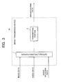
- Fig. 3 is a view of a schematic configuration of the essential parts of an image transmitting device (data transmission device) used in an audio-visual environment control system in a first embodiment of the present invention.
- the image transmission device 10 of the first embodiment includes a data multiplexing portion 1 that multiplexes image data, audio data, and scene situation data supplied as additional data by dividing each of them in a transport stream packet (TSP) format, and a transmitting portion 2 that modulates output data from the data multiplexing portion 1 after adding an error correction code, etc., to the output data and sends the modulated data to a transmission path as broadcasting data.
- TSP transport stream packet
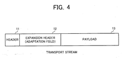
- Fig. 4 is an explanatory view of a schematic configuration of a transport stream packet (TSP) that is a packet format standardized by MPEG2 (Moving Picture Experts Group 2) Systems.
- TPS transport stream packet
- 11 denotes a header containing the description of data specified by MPEG2 including the data contents of the TPS
- 12 denotes an extension header (adaptation field) allowed to contain the description of data determined by a data sender
- 13 denotes a payload composed of image data, audio data, etc.
- the transport stream packet is configured so that image data and audio data are transmitted in the portion of the payload 13 and scene situation data, etc., as additional data is transmitted in the portion of the extension header (adaptation field) 12.
- Image data, audio data, and scene situation data may be transmitted in the form of different data streams by data multiplexing.
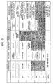
- the scene situation data indicating the scene setting situation of each scene of image data will be described in detail with reference to Fig. 5 .
- the scene situation data of this embodiment include season data representing seasons in stories of scenes, time data representing times in stories of scenes, place data representing places in stories of scenes, period data representing periods in stories of scenes, weather data representing weathers in stories of scenes, and region data representing regions in stories of scenes. All of these pieces of data enable estimation of characteristic illumination environments related to the scene settings of the scenes and are useful data for producing the atmosphere and the feeling of being at a live performance of the scenes with illumination light.
- the feeling of being at a live performance for outdoor scenes is improved by controlling audio-visual environment illumination (described later) to adapt it to the season in the story. That is, for example, although the color temperature of the sunlight in the daytime in spring, summer, and autumn is about 6000 K, the color temperature of the sunlight in winter may be increased to about 7000 K to represent coldness even in the daytime.
- the intensity of the sunlight is high in summer, slightly high in spring/autumn, and moderate in winter. Therefore, in this embodiment, the scene situation data include the season data that is the information expressed in two bits indicating which season the scene setting of each image scene belongs to, spring, summer, autumn, or winter.
- the intensity and the color temperature of natural light also vary depending on the time of day, the feeling of being at a live performance for outdoor scenes is improved by controlling the audio-visual environment illumination (described later) to adapt it to the clock times in the story. That is, for example, the color temperatures of the sunlight are about 2000 K in the early morning, about 3000 K in the morning, about 5000 K in the forenoon, about 6000 K at noon, about 5000 K in the afternoon, about 3000 K in the late afternoon, about 4000 K in the twilight, and about 7000 K in the night.
- the scene situation data include the time data that is the information expressed in three bits indicating when the scene setting of each image scene is, early morning, morning, before noon, noon, afternoon, evening, dusk, or night.
- the feeling of being at a live performance for indoor/outdoor scenes is improved by controlling the audio-visual environment illumination (described later) to adapt it to the place in the story. That is, for example, although only slightly low intensity light of moonlight and street light generally exists outdoors in the night, slightly high intensity light exists indoors even in the night since indoor illumination is turned on. The intensity of illumination light of studios is high day and night and the light intensity becomes moderate in the shade even in the daytime. Therefore, in this embodiment, the scene situation data include the place data that is the information expressed in two bits indicating to which place the scene setting of each image scene belongs to, indoors, studio, outdoors, or shade. Although indoor places where the natural light comes through windows, etc., are considered here, indoor places shielded from the natural light may separately be added.
- the feeling of being at a live performance for contemporary/samurai drama scenes is improved by controlling the audio-visual environment illumination (described later) to adapt it to the period in the story. That is, for example, the color temperatures of the illuminating devices generally used in contemporary dramas are about 5000 K for fluorescent lamps (daylight white color), about 6700 K for fluorescent lamps (daylight color), and about 2800 K for incandescent lamps. On the other hand, the color temperature is about 1800 to 2500 K in the case of candle light frequently used for light sources at night in samurai dramas. The illumination intensity tends to be high in contemporary dramas and low in samurai dramas. Therefore, in this embodiment, the scene situation data include the period data that is the information expressed in one bit indicating which period the period setting of each image scene belongs to, contemporary or samurai drama.
- the intensity and the color temperature of natural light vary depending on weathers, the feeling of being at a live performance for outdoor scenes is improved by controlling the audio-visual environment illumination (described later) to adapt it to the weather in the story. That is, for example, the color temperatures of daylight are about 6000 K in fine weather, 8000 to 9000 K in rainy weather, and about 6500 to 8000 K in cloudy weather.
- the intensity of natural light is maximum in extremely fine weather and decreases in the order of fine (after snow), fine, cloudy, foggy, hazy, misty, thundery, and rainy weather.
- the scene situation data include the weather data that is the information expressed in three bits indicating what weather the weather setting of each image scene belongs to, extremely fine, fine, cloudy, foggy, hazy, misty, thundery, rainy or fine after snow.
- the feeling of being at a live performance for outdoor scenes is improved by controlling the audio-visual environment illumination (described later) to adapt it to the region in the story. That is, for example, the color temperatures of sunlight are about 5000 K in the tropical zone (daytime), about 7000 K in the polar zone (daytime), and about 6000 K in the dry, temperate, and subpolar zones (daytime).
- the intensity of sunlight tends to be very high in the tropical zone and reduces in the order of the zone such as the dry zone, the temperate zone, the subpolar zone, and the polar zone. Therefore, in this embodiment, the scene situation data include the weather data that is the information expressed in three bits indicating which zone the region setting of each image scene belongs to, tropical zone, dry zone, temperate zone, subpolar zone, or polar zone.
- the scene situation data may include the season data and the time data as the time and date data indicating dates and times set in the story of each scene
- the period data may be included in the scene situation data as the period data indicating the age set in the story of each scene
- the region data may be included in the scene situation data as the latitude and longitude data indicating latitude and longitude set in the story of each scene.
- the above scene situation data may be generated using the scene setting situation data in scenario data at the time of image shooting, the work for newly generating the scene situation data may be eliminated.
- the various pieces of data in the above scene situation data may also be used as the scene setting situation data in the scenario data included in broadcasting data as the program additional data, or as the scene setting situation data prepared for editing or retrieval.
- a configuration of image including scenes and shots will then be described with reference to Fig. 6 .
- Image data including continuous dynamic images may be considered by dividing into three layers as shown in Fig. 6 .
- a first layer (#1) composing image (video) is a frame.
- the frame is a physical layer and indicates a single two-dimensional image.
- the frame is usually obtained at the rate of 30 frames per second.
- a second layer (#2) is a shot.
- the shot is a frame sequence shot by a single camera.
- a third layer (#3) is a scene.
- the scene is a shot sequence having connections to compose a story.
- the above scene situation data may be added to each frame, each shot, or each scene of image data.
- the control of the audio-visual environment illumination (described later) may effectively be realized by adding the scene situation data at least to each scene, the audio-visual environment illumination may more finely be controlled by adding the scene situation data to each frame.
- the scene situation data may be added to specific frames (such as scene switching frames) in accordance with the intention of image producers (such as a scenario writer and a director).
- the suitable audio-visual environment illumination control may be realized by adding the scene situation data at least to each shot.
- the scene situation data may be added in each of GOPs (Group of Picture) , which is a unit of random access to image data.
- FIG. 7 is a view of an schematic configuration for explaining an example of an image receiving apparatus in the embodiment of the present invention.
- the image receiving apparatus includes a receiving portion 21 that receives, demodulates broadcasting data input from a transmission channel and performs error correction; a data separating portion 22 that separates/extracts the image data output to an image display device 25, the audio data output to an audio reproducing device 26, and the scene situation data as additional data from the output data of the receiving portion 21; a CPU 23 that outputs control data for the illumination adapted to scene settings (atmospheres) of scenes making up the image data in accordance with the scene situation data separated by the data separating portion 22; and an illumination control data generating portion 24 - that outputs the illumination control data (RGB data) corresponding to the output control data from the CPU 23 to an illuminating device 27 for illuminating the audio-visual environment space.
- a receiving portion 21 that receives, demodulates broadcasting data input from a transmission channel and performs error correction
- a data separating portion 22 that separates/extracts the image data output to an image display device 25, the audio data output to an audio reproducing device 26,
- the illuminating devices 27 are arranged around the image display device 25, and are composed of LEDs that emit light having a given hue, e.g., light having three primary colors of red, green, and blue.
- the illuminating devices 27 are required only to have a structure to be able to control the illumination and brightness of the ambient environment of the image display device 25, and may be composed of a white LED and a color filter, a combination of a white electric lamp or fluorescent lamp and a color filter, or a color lamp, etc., not limited to a combination of LEDs emitting a given color, as described above. Arrangement of one or more illuminating devices 27 is sufficient.
- the CPU 23 determines the intensity and color temperature (a point on a blackbody locus) of illuminating light and outputs the determined intensity and color temperature to the illumination control data generating portion 24 as control data to reproduce the setting situation (atmosphere) in the story of each scene from the scene situation data described in Fig. 5 using audio-visual environment illumination by the illuminating devices 27.
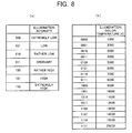
- the CPU 23 based on various types of data contained in the scene situation data, the CPU 23 generates, for example, control data expressing illumination intensities of 7 levels, as shown in Fig. 8(a) , and illumination color temperatures of 16 levels, as shown in Fig. 8(b) .
- a blackbody is an ideal body that absorbs energy completely. Light emitted from the blackbody changes in color from red to yellow to white as the temperature of the blackbody increases.
- the temperature of the blackbody expressed in Kelvin temperature scale is referred to as color temperature.
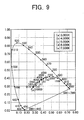
- the color temperature and a color locus (blackbody locus) are plotted on an xy chromaticity graph, as shown in Fig. 9 .
- correlated color temperature the temperature of the blackbody that does not completely match the black locus but is closest thereto.
- the correlated color temperature is expressed with a deflection ( ⁇ uv) from the blackbody locus.
- the illumination control data generating portion 24 generates and outputs to the illuminating device 27 the RGB data corresponding to the control data (intensity and color temperature) from the CPU 23. This enables the optimum audio-visual environment illumination control according to the scene situations of displayed image.
- the illumination control depending on the scene situation data will hereinafter be described with reference to Fig. 10 .
- the scene situation data include the season data of spring, the time data of daytime, the place data of outdoor, and the weather data of fine weather
- the control data are generated to indicate that the illumination intensity is slightly high and that the illumination color temperature is 6000 K (indicated by a point (d) of Fig. 9 ) for reproducing the natural light on this condition.
- the season data turns to summer, the control data are generated to indicate that the illumination intensity is high while maintaining an illumination color temperature of 6000 K.
- the control data are generated to indicate that the illumination intensity is very high. If the season data turns to autumn, the control data are generated to indicate that the illumination intensity is slightly high, and if the season data turns to winter, the control data are generated to indicate that the illumination intensity is moderate and that the illumination color temperature is 7000 K (indicated by a point (e) of Fig. 9 ). If the region data indicates the polar zone, the control data are generated to indicate that the illumination intensity is slightly low. If the region data indicates the polar zone, the control data are generated to indicate that the illumination intensity is slightly low and that the illumination color temperature is 7000 K (indicated by the point (e) of Fig. 9 ).
- the control data are generated to indicate that the illumination intensity is moderate and that the illumination color temperature is 4000 K (indicated by a point (b) of Fig. 9 ) for reproducing the situation that the natural light comes into the room.
- the control data are generated to indicate that the illumination color temperature is 3000 K while maintaining the moderate illumination intensity (indicated by a point (a) of Fig. 9 ).
- the control data are generated to indicate that the illumination intensity is slightly high and that the illumination color temperature is 5000 K (indicated by a point (c) of Fig. 9 ) for reproducing the illumination light of a fluorescent lamp (daylight white color) that is an indoor illuminating device.
- the illumination light source is likely to be flame of a candle, and the control data are generated to indicate that the illumination intensity is slightly low and that the illumination color temperature is 3000 K (indicated by a point (a) of Fig. 9 ) for reproducing this situation.
- the control data are generated to indicate that the illumination intensity is very low and that the illumination color temperature is 7000 K (indicated by the point (e) of Fig. 9 ) for reproducing the atmosphere of moonlight night in samurai dramas.
- the control data are generated to indicate that the illumination intensity is low and that the illumination color temperature is 6000 K (indicated by the point (d) of Fig. 9 ) for reproducing the natural light on this condition.
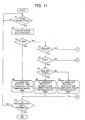
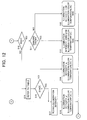
- step S1 It is first determined whether a new scene section starts (step S1), and if the new scene starts, the scene situation data according to the scene are acquired (step S2). If the scene situation data include the place data indicating a studio (step S3), since the illumination light in a studio is not affected by day and night, weathers, etc., the control data are output to indicate that the intensity is high and that the illumination color temperature is 6000 K regardless of other pieces of data (step S4).
- step S5 it is determined whether the time data indicates night (step S6). If the time data indicates night and the period data indicates a samurai drama (step S7), since the illumination light source is likely to be flame of a candle, the control data are output to indicate that the illumination intensity is slightly low and that the illumination color temperature is 3000 K (step S8). If the time data indicates night and the period data indicates present day (step S7), since the illumination light source is likely to be a fluorescent lamp (daylight white color) that is a common indoor illuminating device, the control data are output to indicate that the illumination intensity is slightly high and that the illumination color temperature is 5000 K (step S9).
- step S10 If it is determined that the place is not indoor at step S5, it is determined whether the time data indicates night (step S10). If the time data indicates night and the period data indicates a samurai drama (step S11), the control data are output to indicate that the illumination intensity is very low and that the illumination color temperature is 7000 K (step S12). If the time data indicates night and the period data indicates the present day (step S11), the control data are output to indicate that the illumination intensity is low and that the illumination color temperature is 7000 K (step S13). This is because the outside is relatively bright even at nighttime in the present day due to development of illuminating devices.
- a lookup table prepared in advance (not shown) is referred to in order to acquire the control data indicating that the illumination intensity is "a" and the illumination color temperature is bK, which are specified from a combination of the season data, the time data, the weather data, and the region data (step S14). If the place is not in the shade (step S15), the control data acquired with reference to the lookup table are directly output (step S16).
- the illumination intensity "a" of the control data acquired with reference to the lookup table is reduced only by two stages (levels) (step S17) to output the control data indicating that the illumination intensity is a' and the illumination color temperature is bK (step S18). For example, if the illumination intensity a of the control data acquired with reference to the lookup table is moderate (011), the illumination intensity a' of the output control data is low (001).
- the lookup table has the control data of combinations (960 ways) of the season data (four types), the time data (eight types), the weather data (six types), and the region data (five types) stored for the case of outdoor places.
- the shade and the natural light coming into the room are regarded as the intensity of the outdoor natural light is reduced and the control data is generated with the use of the control data acquired from the lookup table.
- step S19 It is further determined whether broadcasting data are terminated (step S19), and if the broadcasting data are not terminated, the procedure goes back to step S1 to determine whether the next scene section has started. That is, the control data generated as above are retained and output until the next scene section starts or the broadcasting data are terminated.
- the above processing flow is an example for generating the control data and does not limit the scope of the present invention.
- the illumination intensity and the illumination color temperature are obtained from various data contents input as the scene situation data along with image data to appropriately reproduce the setting situations (atmospheres) in stories of scenes, and the illumination light of the illuminating device 27 may be controlled with the corresponding RGB data. Therefore, audio-visual environment illumination that gives a view a natural and pleasant feeling may be realized without being affected by image contents, and the feeling of being at a live performance may be improved.
- the scene situation data may be used to realize various functions other than the control of the audio-visual environment illumination, such as searching and editing desired scenes.
- audio-visual environment illumination is controlled using only the scene situation data contained in broadcasting data.
- audio-visual environment illumination may be controlled also using image data and/or audio data in addition to scene situation data. This case will be described as a second embodiment of the present invention.
- An image transmitting device (data transmission device) of this embodiment is the same as that of the first embodiment described in Fig. 3 and will not be described here.
- Fig. 13 is a view of an schematic configuration for describing an example of an image receiving apparatus (data receiving apparatus) in the embodiment of the present invention, which includes the receiving portion 21 that receives, demodulates broadcasting data input from a transmission channel and correct errors; the data separating portion 22 that separates/extracts the image data and TC (time code) output to the image display device 25, the audio data and TC (time code) output to the audio reproducing device 26, and the scene situation data as additional data, respectively, from the output data of the receiving portion 21; a CPU 33 that receives scene situation data separated at the data separating portion 22 and outputs control data for illumination adapted to scene settings (atmosphere) of each of scenes making up the image data; an illumination control data generating portion 34 that outputs illumination control data (RGB data) corresponding to control data from the CPU 33 to the illuminating devices 27 that illuminate an audio-visual environment space; and delay generating portions 35, 36, and 37 that output image data, audio data, and control data in a delay equal to a processing time
- the CPU 33 of the present embodiment determines the intensity and color temperature (a point on the black locus) of illuminating light for each illuminating device ID, determines data indicating a given color range including the color temperature (function that represents a range indicated by a single-dot-dash line on the xy chromaticity graph of Fig. 15 ), and outputs the determined data as control data.
- the illumination control data generating portion 34 then corrects a situation (atmosphere) estimation result that is obtained based on image data and audio data to place the scene estimation result within the color range that is determined based on the scene situation data, and outputs illumination control data (RGB).
- a time code (TC) is additional data that indicates respective reproduction times of image and audio data, and is, for example, composed of data indicating hours, minutes, seconds, and frames of image data.
- the illumination control data generating portion 34 of the present embodiment has a scene section detecting portion 41 that detects the starting point TC and the ending point TC of a scene section based on scene situation data, a situation (atmosphere) estimating portion 42 that estimates the illumination condition and scene situation (atmosphere) of a shooting scene based on image data and audio data output for a given time from the starting point TC of the scene section, and an illumination control portion 43 that outputs illumination control data for controlling the illuminating devices 27 based on an estimation result from the situation (atmosphere) estimating portion 42 and control data output from the CPU 33.
- the characteristic quantity of audio data is used in addition to the characteristic quantity of image data for estimation of the situation (atmosphere) of each scene. This is for an improvement in the precision of situation (atmosphere) estimation, and the situation (atmosphere) of a shooting scene may be estimated from the characteristic quantity of image data only.
- color signals and luminance signals in a given area on a screen may be directly used as the characteristic quantity of image data in the same manner as described in the above conventional example, or the color temperature of ambient light at the time of shooting may be determined from these color signals and luminance signals to be used as the characteristic quantity.
- These color and luminance signals and color temperature may be output in a switching manner as the characteristic quantity of image data.
- the volume, audio frequency, etc. may be used as the characteristic quantity of audio data.
- the situation (atmosphere) estimating portion 42 estimates the color and brightness of ambient light at the time of shooting based on the characteristic quantity of image data and audio data. If the estimated color of ambient light is out of a given color range derived from scene situation data, the illumination control portion 43 corrects the ambient light color to be able to obtain illumination control data adapted to scene setting situations in the story of each scene.
- the illumination control portion 43 finds an intersection (A') between the straight line connecting the point (A) to the point (a) on the xy chromaticity graph and a function indicating a color range whose center is the point (a) (function that represents an ellipse indicated by a single-dot-dash line on an xy chromaticity graph of Fig. 15 ), and determines a color indicated by the intersection (A') to be the color of audio-visual environment illuminating light.
- the illumination control portion 43 finds an intersection (B') between the straight line connecting the point (B) to the point (e) on the xy chromaticity graph and a function indicating a color range whose center is the point (e) (function that represents an ellipse indicated by a single-dot-dash line on the xy chromaticity graph of Fig. 15 ), and determines a color indicated by the intersection (B') to be the color of audio-visual environment illuminating light.
- the result of estimation of the brightness of ambient light by the situation (atmosphere) estimating portion 42 is properly corrected in correspondence to illumination intensity indicated by control data output from the CPU 33.
- the result of estimation of ambient light by the situation (atmosphere) estimating portion 42 is within a given illumination range determined from scene situation data, the result of estimation of ambient light by the situation (atmosphere) estimating portion 42 is output as it is to the illuminating devices 27 as illumination control data.
- illumination control data to be output to the illuminating devices 27 is obtained from an intersection on the xy chromaticity graph between a straight line connecting an estimation result by the situation (atmosphere) estimating portion 42 to an illumination color temperature indicated by control data output from the CPU 33 and a function representing a color range indicated by control data output from CPU 33.
- a method of obtaining illumination control data is not limited to this one.
- illumination control data may be obtained on the xy chromaticity graph, from a point within a given color range from which point the distance to an estimation result by the situation (atmosphere) estimating portion 42 is the minimum, or from a point within the given color range at which point a color difference ⁇ E between the point and the estimation result by the situation (atmosphere) estimating portion 42 is the minimum.
- the average or weighted average of an estimation result by the situation (atmosphere) estimating portion 42 and an illumination color temperature and illumination intensity indicated by control data output from the CPU 33 may simply be determined to be illumination control data to be output to the illuminating devices 27.
- the above illumination control data is, of course, generated for each illuminating device ID.
- audio-visual environment illumination is controlled using scene situation data, image data, and/or audio data.
- This enables more precise estimation of an illumination environment even in estimation of an illumination environment that is difficult to estimate from scene situation data only, by using a situation (atmosphere) estimation result based on the characteristic quantity of image data and/or audio data, thus enables more proper illumination control.
- the present embodiment also suppresses execution of illumination control hampering the feeling of being at a live performance or atmosphere that is caused by an erroneous estimation of a situation (atmosphere) based on the characteristic quantity of image data and/or audio data, and thus, constantly offers an optimum audio-visual environment.
- data indicating a given color range including the color temperature of illuminating light (function representing a range indicated by a single-dot-dash line on the xy chromaticity graph of Fig. 15 ) is determined based on scene situation data.
- the size of the given color range may be determined variably by a user. The larger the given color range is determined, the bigger the effect is to reproduce the expanse of a screen, and the smaller the given color range is determined, the bigger the effect is to reproduce atmospheres of situations assumed by a producer.
- a user therefore, may variably determine the size of the color range obtained from scene situation data, depending on which illumination effect the user attaches importance to.
- the scene section detecting portion 41 that detects a scene section based on scene situation data is provided to control illumination control data in data switchover on a scene-to-scene basis. This prevents the feeling of being at a live performance from being spoiled due to a violent change of audio-visual environment illumination in the same scene.
- scene situation data is multiplexed and added to broadcasting data to be transmitted.
- scene situation data is not added to broadcasting data, transmitting/receiving scene situation data corresponding to displayed image data to/from an external server, etc., enables achievement of an optimum audio-visual environment corresponding to scene situation of an image. This case will then be described.
- a third embodiment of the audio-visual environment control system of the present invention will hereinafter be described in detail with reference to Fig. 16 to Fig. 18 , and the same portions as those in the first embodiment are given the same reference numerals and will not be described.
- Fig. 16 is a block diagram of a schematic configuration of the essential parts of an external server in the audio-visual environment control system of this embodiment and, as shown in Fig. 16 , the external server (data transmission device) of this embodiment includes a receiving portion 51 that receives a transmission request for the scene situation data related to certain image data (contents) from the image receiving apparatus (data receiving apparatus) , a data storage portion 52 that stores the scene situation data for each of image data (contents) , and a transmitting portion 53 that transmits the requested scene situation data to the image receiving apparatus (data receiving apparatus) that issued the request.
- the external server (data transmission device) of this embodiment includes a receiving portion 51 that receives a transmission request for the scene situation data related to certain image data (contents) from the image receiving apparatus (data receiving apparatus) , a data storage portion 52 that stores the scene situation data for each of image data (contents) , and a transmitting portion 53 that transmits the requested scene situation data to the image receiving apparatus (data receiving apparatus) that issued the request.
- Fig. 17 is an explanatory view of an example of a scene situation data storage table in the audio-visual environment control system of this embodiment.
- Scene situation data stored in the data storing portion 52 of the present embodiment are written in a table format, where scene situation data are linked to scene numbers and scene starting time codes of image scenes, as shown in Fig. 17 .
- the transmitting portion 53 transmits requested scene situation data corresponding to specific image data (program contents) together with scene numbers and scene starting TCs (Time Codes) of scenes making up the image data, to the image receiving apparatus that issued the request.
- Fig. 18 is a block diagram of a schematic configuration of the essential parts of an image receiving apparatus in the audio-visual environment control system of this embodiment. As shown in Fig.
- the image receiving apparatus of the present embodiment includes a receiving portion 61 that receives, demodulates input broadcasting data from a transmission path and corrects errors in the data, a data separating portion 62 that separates and extracts image data output to the image display device 25 and audio data output to the audio reproducing device 26, respectively, from output data from the receiving portion 61, a transmitting portion 65 that sends a transmission request for scene situation data corresponding to displayed image data (contents) to the external server (data transmission device) via a communication network, and a receiving portion 66 that receives the requested scene situation data sent from the external server via the communication network.
- the image receiving apparatus further includes a CPU 63 that stores therein the scene situation data received by the receiving portion 66 and in synchronization with timing to display each scene of image data, outputs control data on illumination intensity and color temperature for each illuminating device ID that is obtained from scene situation data for the image scene, and the illumination control data generating portion 24 that outputs illumination control data (RGB data) corresponding to control data output from the CPU 63 to the illuminating devices 27 that illuminate an audio-visual environment space.
- a CPU 63 that stores therein the scene situation data received by the receiving portion 66 and in synchronization with timing to display each scene of image data, outputs control data on illumination intensity and color temperature for each illuminating device ID that is obtained from scene situation data for the image scene, and the illumination control data generating portion 24 that outputs illumination control data (RGB data) corresponding to control data output from the CPU 63 to the illuminating devices 27 that illuminate an audio-visual environment space.
- RGB data illumination control data
- the CPU 63 compares the starting time code of each scene on a scene situation data storage table which is sent from the external server and is stored inside the CPU 63, with the time code of image data to be displayed on the image display device 25, and when both time codes are identical, the CPU 63 reads out the scene situation data corresponding to the time codes, and then, based on this scene situation data, outputs control data adapted to the scene situation (atmosphere) of a display image scene.
- scene situation data corresponding to displayed image data is obtained from the external server and illumination control data can be generated based on this scene situation data.
- timing of switchover of image scene display can be synchronized with timing of switchover of audio-visual environment illumination in a simple configuration. This enables achievement of an optimum audio-visual environment corresponding to scene situation of an image.
- audio-visual environment illumination may be controlled by using image data and/or audio data in addition to scene situation data. This case will then be described as a fourth embodiment of the present invention.
- the fourth embodiment of the audio-visual environment control system of the present invention will hereinafter be described in detail with reference to Fig. 19 and Fig. 20 , and the same portions as those in the second and third embodiments are given the same reference numerals and will not be described.
- the external server (data transmission device) of this embodiment is the same as that of the third embodiment described in Fig. 18 and will not be described here.
- an image receiving apparatus (data receiving apparatus) of the present embodiment includes the receiving portion 61 that receives and demodulates input broadcasting data from a transmission path, a data separating portion 62 that separates and extracts image data output to the image display device 25 and audio data output to the audio reproducing device 26, from output data from the receiving portion 61, a transmitting portion 65 that sends a transmission request for scene situation data corresponding to display image data (contents) to the external server (data transmission device) via a communication network, and a receiving portion 66 that receives the requested scene situation data sent from the external server via the communication network.
- the image receiving apparatus further includes a CPU 73 that stores therein scene situation data received by the receiving portion 66 and outputs control data on illumination intensity, color temperature, and color range for each illuminating device ID which are obtained from scene situation data for the image scene and a scene starting point time code in synchronization with timing to display each scene of image data, an illumination control data generating portion 74 that outputs illumination control data (RGB data) corresponding to control data output from the CPU 73 to the illuminating device 27 that illuminates an audio-visual environment space, and the delay generating portions 35, 36, and 37 that output image data, audio data, and control data with a delay equal to a processing time spent at the illumination control data generating portion 74.
- a CPU 73 that stores therein scene situation data received by the receiving portion 66 and outputs control data on illumination intensity, color temperature, and color range for each illuminating device ID which are obtained from scene situation data for the image scene and a scene starting point time code in synchronization with timing to display each scene of image data
- the CPU 73 of the present embodiment obtains the intensity and color temperature (a point on the black track) of illuminating light based on scene situation data, determines data indicating a given color range including the color temperature (function that represents a range indicated by a single-dot-dash line on the xy chromaticity graph of Fig. 15 ), and outputs the illuminating light intensity, color temperature, and color range data as control data.
- the illumination control data generating portion 74 then corrects a situation (atmosphere) estimation result that is obtained based on image data and audio data to be within the color range that is determined based on the scene situation data, and outputs illumination control data (RGB data).
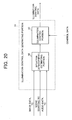
- Fig. 20 is a block diagram of the illumination control data generating portion shown in Fig. 19 .
- the illumination control data generating portion 74 of the present embodiment has a situation (atmosphere) estimating portion 82 that estimates the illumination condition and scene situation (atmosphere) of a shooting scene based on image data and audio data output for a given time from the scene starting point TC that is sent from the CPU 73, and the illumination control portion 43 that outputs illumination control data for controlling the illuminating devices 27, based on an estimation result from the situation (atmosphere) estimating portion 82 and control data output from the CPU 73.
- a situation (atmosphere) estimating portion 82 that estimates the illumination condition and scene situation (atmosphere) of a shooting scene based on image data and audio data output for a given time from the scene starting point TC that is sent from the CPU 73
- the illumination control portion 43 that outputs illumination control data for controlling the illuminating devices 27, based on an estimation result from the situation (atmo
- the situation (atmosphere) estimating portion 82 estimates the color and brightness of ambient light at the time of shooting based on the characteristic quantity of image data and audio data. If the estimated color of ambient light is out of a given color range obtained from scene situation data, the illumination control portion 43 corrects the ambient light color to be able to obtain illumination control data appropriate to the scene setting situations in the story of each scene.
- scene situation data corresponding to displayed image data is obtained from the external server to control audio-visual environment illumination using this scene situation data and image data and/or audio data.
- This enables illumination control that takes account of the result of estimation of a situation (atmosphere) based on the characteristic quantity of image data and/or audio data in addition to scene situation data, and suppresses execution of illumination control hampering the feeling of being at a live performance or atmosphere that is caused by an erroneous estimation of a situation (atmosphere) based on the characteristic quantity of image data and/or audio data, thus constantly offers an optimum audio-visual environment.
- data indicating a given color range including the color temperature of illuminating light (function representing a range indicated by a single-dot-dash line on the xy chromaticity graph of Fig. 15 ) is determined based on scene situation data.
- the size of the given color range may be determined variably by a user. The larger the given color range is determined, the bigger the effect is to reproduce the expanse of a screen, and the smaller the given color range is determined, the bigger the effect is to reproduce the atmosphere of situations assumed by a producer.
- the user therefore, may variably determine the size of the color range obtained from scene situation data, depending on which of the illumination effects the user emphasizes.
- illumination control data is controlled in data switchover on a scene-to-scene basis based on scene starting time codes on the scene situation data storage table. This prevents the feeling of being at a live performance from being spoiled due to a violent change of audio-visual environment illumination in the same scene.
- the audio-visual environment control device, audio-visual environment control method, and the audio-visual environment control system of the present invention may be realized in various embodiments without deviating from the substance of the present invention.
- the audio-visual environment control device may be incorporated in the image display device, where the audio-visual environment control device is, of course, capable of controlling external illuminating equipment based on various data contained in input image data.
- the above described scene situation data is not limited to be obtained from the external server or by separating from broadcasting data.
- scene situation data added to a recording medium may be read out to be used.
Landscapes
- Engineering & Computer Science (AREA)
- Multimedia (AREA)
- Signal Processing (AREA)
- Automation & Control Theory (AREA)
- Computer Security & Cryptography (AREA)
- Circuit Arrangement For Electric Light Sources In General (AREA)
- Two-Way Televisions, Distribution Of Moving Picture Or The Like (AREA)
Applications Claiming Priority (2)
| Application Number | Priority Date | Filing Date | Title |
|---|---|---|---|
| JP2006115099 | 2006-04-19 | ||
| PCT/JP2007/057458 WO2007122987A1 (fr) | 2006-04-19 | 2007-04-03 | Procédé et dispositif de transmission de données, et dispositif, système et procédé de gestion d'environnement audiovisuel |
Publications (2)
| Publication Number | Publication Date |
|---|---|
| EP2018061A1 true EP2018061A1 (fr) | 2009-01-21 |
| EP2018061A4 EP2018061A4 (fr) | 2010-11-10 |
Family
ID=38624895
Family Applications (1)
| Application Number | Title | Priority Date | Filing Date |
|---|---|---|---|
| EP07740894A Withdrawn EP2018061A4 (fr) | 2006-04-19 | 2007-04-03 | Procede et dispositif de transmission de donnees, et dispositif, systeme et procede de gestion d'environnement audiovisuel |
Country Status (5)
| Country | Link |
|---|---|
| US (1) | US20090256962A1 (fr) |
| EP (1) | EP2018061A4 (fr) |
| JP (1) | JP5058157B2 (fr) |
| CN (1) | CN101427577A (fr) |
| WO (1) | WO2007122987A1 (fr) |
Cited By (2)
| Publication number | Priority date | Publication date | Assignee | Title |
|---|---|---|---|---|
| EP2315441A4 (fr) * | 2008-07-15 | 2014-07-16 | Sharp Kk | Dispositif d'émission de données, dispositif de réception de données, procédé d'émission de données, procédé de réception de données et procédé de commande d'environnement audiovisuel |
| EP3344016A4 (fr) * | 2015-08-26 | 2018-08-01 | Panasonic Intellectual Property Management Co., Ltd. | Système et programme d'éclairage |
Families Citing this family (12)
| Publication number | Priority date | Publication date | Assignee | Title |
|---|---|---|---|---|
| CN101463963B (zh) * | 2007-12-21 | 2010-09-29 | 富士迈半导体精密工业(上海)有限公司 | 照明系统 |
| JP5226361B2 (ja) * | 2008-04-09 | 2013-07-03 | キヤノン株式会社 | 放送受信装置、放送受信方法 |
| JP2011023339A (ja) * | 2009-06-15 | 2011-02-03 | Motoko Ishii Lighting Design Inc | 照度・色温度による制御装置を装備した照明システム |
| EP2514275B1 (fr) * | 2009-12-17 | 2015-04-22 | Koninklijke Philips N.V. | Système d'éclairage d'ambiance pour salle de cinéma |
| CN103068095A (zh) * | 2011-10-21 | 2013-04-24 | 扬升照明股份有限公司 | 照明系统及照明系统的控制方法 |
| EP4024454B1 (fr) * | 2014-10-28 | 2023-08-30 | Seoul Semiconductor Co., Ltd. | Système de source de lumière blanche |
| JP2016161812A (ja) | 2015-03-03 | 2016-09-05 | パナソニックIpマネジメント株式会社 | 映像表示装置 |
| US9961231B2 (en) * | 2015-10-06 | 2018-05-01 | Canon Kabushiki Kaisha | Image processing method that attempts decoding of additional information using a plurality of decoding methods, and apparatus therefor |
| CN105245865A (zh) * | 2015-10-09 | 2016-01-13 | 深圳Tcl数字技术有限公司 | 色温调整方法及装置 |
| CN106792168A (zh) * | 2016-12-09 | 2017-05-31 | 北京小米移动软件有限公司 | 智能设备的控制方法和装置 |
| IT201700099120A1 (it) * | 2017-09-05 | 2019-03-05 | Salvatore Lamanna | Sistema di illuminazione per schermo di qualsiasi tipo |
| US10609294B2 (en) * | 2017-12-22 | 2020-03-31 | X Development LLP | Systems and methods for sampling images |
Family Cites Families (16)
| Publication number | Priority date | Publication date | Assignee | Title |
|---|---|---|---|---|
| JP4802350B2 (ja) * | 1998-03-12 | 2011-10-26 | ソニー株式会社 | 表示装置 |
| JPH0812793B2 (ja) | 1988-12-12 | 1996-02-07 | 松下電器産業株式会社 | 光色可変形照明装置 |
| JPH02253503A (ja) | 1989-03-28 | 1990-10-12 | Matsushita Electric Works Ltd | 映像演出照明装置 |
| JPH0815004B2 (ja) | 1989-12-14 | 1996-02-14 | 松下電器産業株式会社 | 光色可変形照明装置 |
| WO1999053728A1 (fr) * | 1998-04-13 | 1999-10-21 | Matsushita Electric Industrial Co., Ltd. | Procede de regulation d'un eclairage et dispositif d'eclairage |
| JP2001343930A (ja) * | 2000-05-31 | 2001-12-14 | Lg Electronics Inc | 表示装置及び表示装置の階調表示方法 |
| JP4399087B2 (ja) * | 2000-05-31 | 2010-01-13 | パナソニック株式会社 | 照明システム、映像表示デバイスおよび照明制御方法 |
| JP3644502B2 (ja) * | 2001-02-06 | 2005-04-27 | ソニー株式会社 | コンテンツ受信装置およびコンテンツ呈示制御方法 |
| JP2002297753A (ja) * | 2001-03-30 | 2002-10-11 | Fujitsu Ltd | 画像データ提供システム |
| KR100497497B1 (ko) * | 2001-12-27 | 2005-07-01 | 삼성전자주식회사 | 엠펙 데이터의 송수신시스템 및 송수신방법 |
| GB0211898D0 (en) * | 2002-05-23 | 2002-07-03 | Koninkl Philips Electronics Nv | Controlling ambient light |
| WO2004006578A2 (fr) * | 2002-07-04 | 2004-01-15 | Koninklijke Philips Electronics N.V. | Procede et systeme de regulation de la lumiere ambiante et unite d'eclairage |
| US20070165048A1 (en) * | 2003-09-11 | 2007-07-19 | Matsushita Electric Industrial Co., Ltd. | Image processing device, image processing method, and image processing program |
| US7352808B2 (en) * | 2004-01-29 | 2008-04-01 | International Business Machines Corporation | System and method for the dynamic resolution change for video encoding |
| JP2005229153A (ja) * | 2004-02-10 | 2005-08-25 | Sony Corp | 調光システムおよび調光方法、配信装置および配信方法、受信装置および受信方法、記録装置および記録方法、ならびに、再生装置および再生方法 |
| JP4439322B2 (ja) * | 2004-04-23 | 2010-03-24 | シャープ株式会社 | 高臨場感再生装置及び方法 |
-
2007
- 2007-04-03 CN CNA2007800140626A patent/CN101427577A/zh active Pending
- 2007-04-03 EP EP07740894A patent/EP2018061A4/fr not_active Withdrawn
- 2007-04-03 US US12/297,187 patent/US20090256962A1/en not_active Abandoned
- 2007-04-03 WO PCT/JP2007/057458 patent/WO2007122987A1/fr not_active Ceased
- 2007-04-03 JP JP2008512054A patent/JP5058157B2/ja not_active Expired - Fee Related
Cited By (2)
| Publication number | Priority date | Publication date | Assignee | Title |
|---|---|---|---|---|
| EP2315441A4 (fr) * | 2008-07-15 | 2014-07-16 | Sharp Kk | Dispositif d'émission de données, dispositif de réception de données, procédé d'émission de données, procédé de réception de données et procédé de commande d'environnement audiovisuel |
| EP3344016A4 (fr) * | 2015-08-26 | 2018-08-01 | Panasonic Intellectual Property Management Co., Ltd. | Système et programme d'éclairage |
Also Published As
| Publication number | Publication date |
|---|---|
| EP2018061A4 (fr) | 2010-11-10 |
| JP5058157B2 (ja) | 2012-10-24 |
| US20090256962A1 (en) | 2009-10-15 |
| JPWO2007122987A1 (ja) | 2009-09-03 |
| CN101427577A (zh) | 2009-05-06 |
| WO2007122987A1 (fr) | 2007-11-01 |
Similar Documents
| Publication | Publication Date | Title |
|---|---|---|
| EP2018061A1 (fr) | Procede et dispositif de transmission de donnees, et dispositif, systeme et procede de gestion d'environnement audiovisuel | |
| US20090109340A1 (en) | Data Transmission Device, Data Transmission Method, Audio-Visual Environment Control Device, Audio-Visual Environment Control System, And Audio-Visual Environment Control Method | |
| EP2040472A1 (fr) | Dispositif et procédé de transmission de données, ainsi que dispositif, système et procédé de commande de l'environnement audiovisuel | |
| JP6700322B2 (ja) | 改善されたhdrイメージ符号化及び復号化方法、装置 | |
| JP6596125B2 (ja) | Hdrイメージの符号化のためのコードマッピング関数を作成するための方法及び装置、並びに、かかる符号化イメージの使用のための方法及び装置 | |
| EP3381179B1 (fr) | Manipulation de multiples sources d'image hdr | |
| US20090123086A1 (en) | View environment control system | |
| RU2652465C2 (ru) | Усовершенствованные способы и устройства для кодирования и декодирования hdr изображений | |
| JP4889731B2 (ja) | 視聴環境制御装置、視聴環境制御システム、及び視聴環境制御方法 | |
| CN103119936A (zh) | 用于图像的改进的编码的设备和方法 | |
| JP6831389B2 (ja) | 複数のhdr画像ソースの処理 | |
| CN102282849A (zh) | 数据发送装置、数据发送方法、视听环境控制装置、视听环境控制方法以及视听环境控制系统 | |
| JP2005229153A (ja) | 調光システムおよび調光方法、配信装置および配信方法、受信装置および受信方法、記録装置および記録方法、ならびに、再生装置および再生方法 | |
| JP2009081822A (ja) | データ送信装置、データ送信方法、視聴環境制御装置、視聴環境制御システム、及び視聴環境制御方法 | |
| JP5074864B2 (ja) | データ送信装置、データ送信方法、視聴環境制御装置、視聴環境制御システム、及び視聴環境制御方法 | |
| JP4789592B2 (ja) | 視聴環境制御装置及び視聴環境制御方法 | |
| JP2009060542A (ja) | データ送信装置、データ送信方法、視聴環境制御装置、視聴環境制御システム、及び視聴環境制御方法 | |
| JP2009081482A (ja) | データ送信装置、データ送信方法、視聴環境制御装置、視聴環境制御システム、及び視聴環境制御方法 | |
| JP7752792B2 (ja) | Hdr画像内の二次グラフィック要素の混合 | |
| Siniscalco | A design approach to lighting and colour rendering in indoor sets | |
| JP4709897B2 (ja) | 視聴環境制御システム、視聴環境制御装置、視聴環境照明制御システム、及び視聴環境制御方法 |
Legal Events
| Date | Code | Title | Description |
|---|---|---|---|
| PUAI | Public reference made under article 153(3) epc to a published international application that has entered the european phase |
Free format text: ORIGINAL CODE: 0009012 |
|
| 17P | Request for examination filed |
Effective date: 20081118 |
|
| AK | Designated contracting states |
Kind code of ref document: A1 Designated state(s): AT BE BG CH CY CZ DE DK EE ES FI FR GB GR HU IE IS IT LI LT LU LV MC MT NL PL PT RO SE SI SK TR |
|
| AX | Request for extension of the european patent |
Extension state: AL BA HR MK RS |
|
| A4 | Supplementary search report drawn up and despatched |
Effective date: 20101008 |
|
| 17Q | First examination report despatched |
Effective date: 20111007 |
|
| DAX | Request for extension of the european patent (deleted) | ||
| STAA | Information on the status of an ep patent application or granted ep patent |
Free format text: STATUS: THE APPLICATION IS DEEMED TO BE WITHDRAWN |
|
| 18D | Application deemed to be withdrawn |
Effective date: 20131101 |