EP2018072A1 - Verfahren, einrichtung und system zur kanalkonfiguration - Google Patents
Verfahren, einrichtung und system zur kanalkonfiguration Download PDFInfo
- Publication number
- EP2018072A1 EP2018072A1 EP07710859A EP07710859A EP2018072A1 EP 2018072 A1 EP2018072 A1 EP 2018072A1 EP 07710859 A EP07710859 A EP 07710859A EP 07710859 A EP07710859 A EP 07710859A EP 2018072 A1 EP2018072 A1 EP 2018072A1
- Authority
- EP
- European Patent Office
- Prior art keywords
- message
- channel
- call
- type information
- radio bearer
- Prior art date
- Legal status (The legal status is an assumption and is not a legal conclusion. Google has not performed a legal analysis and makes no representation as to the accuracy of the status listed.)
- Granted
Links
Images





Classifications
-
- H—ELECTRICITY
- H04—ELECTRIC COMMUNICATION TECHNIQUE
- H04W—WIRELESS COMMUNICATION NETWORKS
- H04W76/00—Connection management
- H04W76/10—Connection setup
Definitions
- the invention relates to the field of mobile communications, and in particular, to a method, device and system for channel configuration.
- a Wideband Code Division Multiple Access (WCDMA) system provides the access and transmission of Broadcast (BC) domain, Circuit Switched (CS) domain, and Packet Switched (PS) domain.
- BC domain provides broadcasting within the system
- CS domain provides the access and transmission of circuit switched services (mostly voice services)
- PS domain provides the access and transmission of packet switched services (mostly IP packets).
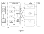
- Figure 1 shows the structure of a WCDMA system.
- a user equipment e.g. a mobile station
- UE usually works in one of two basic modes, i.e. an idle mode and a connection mode.
- the so-called idle mode means that the UE is in a standby state, i.e. a no-service state.
- the so-called connection mode means that the UE is in a state in which the Radio Resource Control (RRC) connection has been established between the UE and a Radio Network Controller (RNC). At this time, the UE is in a cell.
- RRC Radio Resource Control
- RNC Radio Network Controller
- the UE in the connection mode, the UE usually has 4 status including Cell Dedicated Channel (CELL_DCH) status, Cell Forward Access Channel (CELL_FACH) status, Cell Paging Channel (CELL_PCH) status, and Universal Terrestrial Radio Access Network Paging Channel (URA_PCH) status.
- CELL_DCH Cell Dedicated Channel
- CELL_FACH Cell Forward Access Channel
- CELL_PCH Cell Paging Channel
- UUA_PCH Universal Terrestrial Radio Access Network Paging Channel
- the CELL_DCH status is a status in which the UE has a dedicated control channel (DCCH) and a dedicated traffic channel (DTCH) and communicates by using the dedicated (or shared) channels.
- DCCH dedicated control channel
- DTCH dedicated traffic channel
- the CELL_FACH status is a status in which the UE has the DCCH and DTCH and can receive data in the forward access channel (FACH), transmit data in the random access channel (RACH) and transfer messages in the common FACH/RACH channels without the need of allocating dedicated channels.
- FACH forward access channel
- RACH random access channel
- the CELL_PCH status is a status in which the UE can not utilize the DCCH and DTCH, but listens to the paging indicator channel (PICH) in the downlink.
- the UE may transmit CELL Update (update of cell) messages to the RNC.
- the URA_PCH status is a status in which the UE can not utilize the DCCH and DTCH and can not transmit or receive data, but listens to the paging indicator messages on the PICH channel in the downlink.
- the UE may transmit URA Update (Update of registration area of Universal Terrestrial Radio Access Network) messages and CELL Update messages to the RNC.
- URA Update Update of registration area of Universal Terrestrial Radio Access Network
- the transition between the statuses of the UE is decided by the radio network controller according to its radio resource managing and scheduling algorithm.
- the radio network controller allocates dedicated channels to a UE when the UE performs CS domain services. At this time, the UE is in the CELL_DCH status.
- the radio network controller does not allocate dedicated channels to the UE so that the UE is put in the CELL_FACH status, and if the service traffic is relatively heavy, the radio network controller allocates dedicated channels to the UE.
- the UE may have no uplink or downlink data transmission sometimes. At these times, the radio network controller may cause the UE to enter the CELL_PCH or URA_PPCH status.
- the UE When entering the CELL_PCH or URA_PPCH status from the CELL_FACH or CELL_DCH status, the UE listens to the information of the paging indicator channel (PICH), but can not transmit and receive data.
- PICH paging indicator channel
- the purpose of keeping the UE in the CELL_PCH status is to save the power consumption of the UE and maintain the RRC connection and the connection with the core network (CN) to shorten the time for establishing the radio bearer and resuming the data transmission.
- URA_PCH status is to further reduce the signaling message flow due to the cell update. If the UE has not service flow for a long time, the UE enters the URA_PCH status.
- Universal terrestrial radio access network registration area usually includes a plurality of cells.
- URA_PCH status if the UE enters another cell within the same URA, the cell update process is not be initiated, so that the radio resources may be saved.
- the working mode of the UE is transparent to the core network.
- Figure 2 is a flow chart showing the process of initiating a CS domain call by the UE in the CELL_PCH or URA_PCH status.
- step S202 the UE sends a cell update message to the RNC.
- step S204 the RNC sends a cell update confirm message, carrying configuration information, to the UE in response to the received cell update message.
- step S206 the UE configures a physical channel according to the configuration information, and performs physical layer synchronization with the base station (Node B).
- step S208 the UE sends an initial direct transfer message to the RNC, and the RNC sends an initial UE message to the CN in response to the received initial direct transfer message, and the CN performs the processes such as authentication and authorization.
- step S210 the CN sends to the RNC a radio access bearer (RAB) assignment request message including the relevant configuration information of radio access bearer to be established for service data transmission.
- RNC radio access bearer
- step S212 the RNC sends a radio bearer setup message including the configuration information of the radio bearer to the UE according to the relevant configuration information of the radio access bearer.
- step S214 the UE configures the physical channel according to the configuration information of the radio bearer and performs physical layer synchronization with the base station again.
- step S216 the UE sends a radio bearer setup complete message to the RNC.
- step S2108 the RNC sends an RAB assignment response message to the CN in response to the received radio bearer setup complete message.
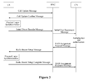
- Figure 3 is a signaling flow chart showing the process of initiating the CS domain call by the UE in the CELL_PCH or URA_PCH status.
- the RNC since the RNC does not know the type of the CS domain call to be established during the cell update, the RNC can not allocate the radio resources for the call session in advance and can not pre-configure the physical channel resources used by the radio bearer for service data transmission in the cell update confirm message. This configuration can be done by the RNC only in the subsequent radio bearer setup message. In this way, the UE is required to perform the physical channel configuration and physical layer synchronization twice, i.e. one time in the step S202 of cell update and another time in the step S214 for radio bearer setup. The establishment of the call is delayed due to the time required in the physical layer synchronization (about 160ms). This can deteriorate the user's service experience and can thus reduce the user's satisfaction.
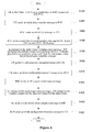
- Figure 4 is a flow chart showing the process of initiating a CS domain call by the UE in the CELL_FACH status.
- step S402 the UE in the CELL_FACH status establishes an RRC connection with the RNC.
- the UE sends an initial direct transfer message to the RNC.
- the initial direct transfer message is used for the reason for establishing the call (the voice call initiated this time) and carries the information of Non Access Stratum (NAS).
- the RNC sends an initial UE message to the CN to forward the above information of NAS to the CN.
- step S408 the RNC sends a radio bearer reconfiguration message to the UE, to put the UE into the CELL_DCH status.
- the radio bearer reconfiguration message carries configuration information.
- the configuration information is used to configure only the dedicated transfer channel and the dedicated physical channel resources used for signaling radio bearer (SRB), and to map the SRB to the dedicated transfer channel.
- SRB signaling radio bearer
- step S410 in response to the radio bearer reconfiguration message, the UE configures the transfer channel and physical channel according to the configuration information of the channels included in the radio bearer reconfiguration message, and performs physical layer synchronization with the Node B, and sends a radio bearer reconfigure complete message to the RNC.
- step S412 the UE performs the authentication and authorization with the CN.
- step S414 the CN sends to the RNC a radio access bearer (RAB) configuration request message containing the relevant configuration information of radio bearer to be setup for service data transmission.
- RAB radio access bearer
- step S416 in response to the RAB configuration request message, the RNC sends to the UE a radio bearer setup message containing configuration information of the radio bearer.
- the transfer channel and physical channel resources required by the radio bearer are also configured. Since the physical layer resources setup in this step S416 is different from the resources setup in the step S308, the radio bearer may be setup in radio synchronization manner. The system is relatively simple, and the radio resources are not wasted.
- step S418 in response to the radio bearer setup message, the UE configures the transfer channel and the physical channel of the radio bearer according to the configuration information in the radio bearer setup message, and performs physical layer synchronization with the Node B.
- step S420 the UE sends a radio bearer setup complete message to the RNC.
- step S422 the RCN sends an RAB configuration response message to the CN in response to the radio bearer setup complete message.
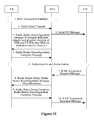
- Figure 5 shows a signaling flow chart showing the process of initiating the CS domain call by the UE in the CELL_FACH status.
- the RNC changes the status of the UE to be CELL_DCH according to the reason of establishing the call.
- the RNC does not know the type of the CS call to be established by the UE, therefore the RNC can not pre-configure the physical resources for the radio bearer in step S408. Accordingly, in the subsequent step S416, a synchronous method for the radio bearer setup has to be adopted (that is, the UE and the Node B are required to switch to the new radio bearer at a time appointed by both of the UE and Node B).
- the disadvantages of the existing technologies lie in that: when the UE initiates a CS domain call, the RNC does not know the type of the CS call to be established by the UE and therefore can not pre-configure the physical resources for the radio bearer, no matter whether the UE is in the CELL_PCH or URA_PCH status or in the CELL_FACH status when initiating the CS domain call.
- the RNC has to configure the physical resources in the subsequent radio bearer setup message. In this way, the UE is required to perform the physical channel configuration and the physical layer synchronization with the Node B twice. In addition, this increases the delay in establishing the CS domain call. In this case, if an asynchronous method is adopted, the processing of the UE and the Node B will be very complicated, resulting in a waste of the radio resources and a degradation of user experience.
- Embodiments of the invention are to provide a method, a device and a system for channel configuration, to solve the problem of delay when initiating a call by a UE in the existing technologies.
- an embodiment of the invention provides a method for channel configuration.
- the method includes:
- Another embodiment of the invention provides a method for channel configuration.
- the method includes:
- Another embodiment of the invention provides a method for channel configuration.
- the method includes:
- an embodiment of the invention provides a device for channel configuration.
- the device includes:
- Another embodiment of the invention provides a device for channel configuration.
- the device includes:
- Another embodiment of the invention provides a system for channel configuration.
- the system includes:
- the UE when initiating a CS domain call in CELL_PCH, URA_PCH or CELL_FACH status, the UE transmits the type information of the call to the network side.
- the network side may pre-allocate the channel resources to be used by the radio bearer according to the type of the call.
- the number of synchronization processes may be reduced, that is, the number of synchronization processes between the UE and Node B is reduced to one (which is two in the existing technologies).
- An asynchronous method is adopted in the subsequent process of radio bearer setup for the CS services, so that the time required by the UE for establishing the call may be shortened.
- the complicity of the system is reduced, thereby avoiding the waste of the radio resources.
- Figure 1 is a diagram illustrating the structure of a WCHMA system in the existing technology
- Figure 2 is a flow chart illustrating the process of initiating a CS domain call by a UE in the CELL_PCH or URA_PCH status;
- Figure 3 is a signaling flow chart illustrating the process of initiating a CS domain call by the UE in the CELL_PCH or URA_PCH status;
- Figure 4 is a flow chart illustrating the process of initiating a CS domain call by a UE in the CELL_FACH status
- Figure 5 is a signaling flow chart illustrating the process of initiating a CS domain call by the UE in the CELL_FACH status
- Figure 6 is a flow chart illustrating a method for channel configuration according to a first embodiment of the invention
- Figure 7 is a flow chart illustrating the process of establishing the physical channels according to the first embodiment of the invention.
- Figure 8 is a flow chart illustrating the process for radio bearer setup based on the process as shown in Figure 7 ;
- Figure 9 is a signaling flow chart illustrating the process of initiating a CS domain call by a UE in the CELL_PCH or URA_PCH status according to the first embodiment of the invention
- Figure 10 is a flow chart illustrating the process of initiating a CS domain call by a UE in the CELL_FACH status according to a third embodiment of the invention.
- Figure 11 is a signaling flow chart illustrating the process of initiating the CS domain call by the UE in the CELL_FACH status as shown in Figure 10 ;
- Figure 12 is another signaling flow chart illustrating the process of initiating the CS domain call by a UE in the CELL_FACH status according to a fourth embodiment of the invention.
- Figure 13 is a flow chart illustrating a method for channel configuration according to a fifth embodiment of the invention.
- Figure 14 is a flow chart illustrating a method for channel configuration according to a sixth embodiment of the invention.
- Figure 15 is a schematic diagram illustrating the structure of a device for channel configuration according to a seventh embodiment of the invention.
- Figure 16 is a schematic diagram illustrating the structure of a device for channel configuration according to an eighth embodiment of the invention.
- Figure 17 is a schematic diagram illustrating the structure of a system for channel configuration according to a ninth embodiment of the invention.
- Figure 6 is a flow chart illustrating a method for channel configuration according to an embodiment of the invention. As shown in Figure 6 , the method for channel configuration includes the following steps.
- Step 602 A UE in a connection mode transmits type information of a call to network side.
- Step 604 The network side feeds back corresponding configuration information of a channel(s) to the UE according to the type information of the call.
- Step 606 The UE configures a channel(s) according to the received configuration information of the channel(s).
- FIG. 7 is a flow chart illustrating the process of establishing the physical channels according to the embodiment of the invention.
- the UE sends a cell update message to the radio network controller (RNC).
- the cell update message includes type information of a CS domain call.
- the CS domain call is categorized into the following types: for example, CS domain speech (CS Speech) service and CS domain video telephone (CS Video) service. There are other types of CS domain call, that is, the type should not be limited to these.
- the RNC responds to the cell update message, that is, the RNC sends a cell update response message (or a cell update confirm message) to the UE.
- the cell update response message includes configuration information of the physical channel(s) (i.e. configuration parameters of the physical channel(s)).
- the UE pre-configures the physical channel(s) according to the configuration parameters of the physical channel(s) contained in the cell update response message, and performs physical layer synchronization with the Node B. In this way, the physical channel(s) is configured.
- the RNC may optionally send the configuration parameters of the physical channel(s) in other message, such as other signaling for controlling radio resources, instead of the cell update response message (or cell update confirm message) transmitted to the UE.
- FIG 8 is a flow chart illustrating the process for radio bearer setup based on the process as shown in Figure 7 , after the UE has configured the physical channel(s).
- the UE sends an initial direct transfer message to the RNC.
- the RNC sends an initial UE message to the CN.
- the CN sends to the RNC an RAB configuration request message containing information of radio bearer setup or radio bearer reconfiguration.
- the RNC in response to the RAB configuration request message, the RNC sends to the UE a radio bearer (RB) setup message or RB reconfiguration message containing information of RB configuration.
- RB radio bearer
- step S810 the UE configures the radio bearer according to the information of RB configuration, and need not to perform physical layer synchronization with the node B. In this way, the radio bearer is set up or configured.
- the UE may send to the RNC an RB setup complete message or RB reconfiguration complete message, to notify the RNC that the radio bearer has been set up or reconfigured.
- the RNC sends an RAB configuration response message to the CN.
- Figure 9 shows a flow chart illustrating the particular signaling for establishing the physical channel and the radio bearer thereof.
- an information element of "Call Type" is added in the cell update message in the embodiment, as shown in the following Table 1.
- Table 1 Information Element/Group name Need Multi Type and reference Semantics description Version Message Type MP
- Message Type UE information elements U-RNTI MP U-RNTI 10.3.3.47
- RRC transaction identifier CV-Fail ure
- RRC transactio n identifier 10.3.3.36
- Integrity check info CH Integrity check info 10.3.3.16 START list MP 1 to ⁇ maxC Ndomai ns> START [40] values for all CN domains.
- AM_RLC error indication(RB2, RB3 or RB4) MP Boolean TRUE indicates AM_RLC unrecoverable error [16] occurred on RB2, RB3 or RB4 in the UE
- MP Boolean TRUE indicates AM_RLC unrecoverable error [16] occurred on RB>4 in the UE Cell update cause MP Cell update cause 10.3.3.3 Traffic volume indicator OP Enumerat ed (true) This IE shall be set to TRUE when the criteria for event based traffic volume measurement reporting is fulfilled. Absence of this element means not fulfilled.
- Rel-6 Failure cause OP Failure cause and error informatio n 10.3.3.14 RB timer indicator MP RB timer indicator 10.3.3.28 Establishment cause OP Establish ment cause 10.3.3.11 Rel-5 Call type OP Enumerat ed (CS speech, CS video, other) One spare value is needed
- REL-6 Reconfiguration Status Indicator OP Enumerat ed (true) TRUE indicates a reconfiguration procedure is ongoing within the UE or a response message has been submitted to RLC and the UE is waiting for the layer 2 ACK.
- Rel-6 Measurement information elements Measured results on RACH OP Measured results on RACH 10.3.7.45
- the information element (IE) "Call Type” defines two types of services including CS Speech and CS Video (as shown in the bold words in the Table 1) and other types of services.
- the IE is required to be included, and the value of the IE is set to a value corresponding to the service type to be established.
- the RNC may judge the service type to be established by the UE according to the IE and the value of the IE, decide to pre-configure the physical channel of the radio bearer corresponding to the service type according to the state of the current resources of the system, and transfer the information of pre-configuration to the UE by using a cell update response message or cell update confirm message (or other signaling for controlling radio resources).
- the second embodiment of the invention is different from the first embodiment in that: the UE sends a Universal terrestrial Radio Access network registration area Update (URA update) message to the RNC in step S702 and the RNC sends to the UE a URA update response message (or URA update confirm message) in step S804. Except for the above differences, the second embodiment of the invention is the same as the first embodiment. The process of the second embodiment is similar to that of the first embodiment, and is not described herein.
- URA update Universal terrestrial Radio Access network registration area Update
- an information element of "Call Type" is added in the URA update message in the embodiment, as shown in the following Table 2.
- the invention should not be limited to table 2.
- the information element (IE) "Call Type" defines two types of services including CS Speech and CS Video and other types of services.
- the IE is required to be included, and the value of the IE is set to a value corresponding to the service type to be established.
- the RNC may judge the service type to be established by the UE according to the IE and the value of the IE, decide to pre-configure the physical channel of the radio bearer corresponding to the service type according to the state of the current resources of the system, and transfer the information of pre-configuration to the UE by using a URA update response message or URA update confirm message (or other signaling for controlling radio resources).
- Figure 10 shows a flow chart illustrating the process of initiating a CS domain call by a UE in the CELL_FACH status.
- the UE sends an initial direct transfer message to the RNC.
- the initial direct transfer message contains type information of the voice call (e.g. CS Speech, CS Video), as well as information of Non Access Stratum (NAS).
- NAS Non Access Stratum
- the initial direct transfer message is mainly transferred to carry the information of NAS to the core network (CN). Therefore the RNC transfers the information of NAS to the CN transparently without any processing.
- step S1004 the RNC transmits an initial UE message to the CN in response to the initial direct transfer message.
- the initial UE message contains the information of NAS.
- step S 1006 the RNC sends a radio bearer reconfiguration message to the UE according to the type information of the voice call.
- the radio bearer reconfiguration message contains configuration information of channels.
- the configuration information of channels are the configuration information of the dedicated transfer channel and dedicated physical channel used by the signaling radio bearer (SRB) and circuit service radio bearer (CS RB).
- SRB signaling radio bearer
- CS RB circuit service radio bearer
- the RNC maps the SRB to the dedicated transfer channel.
- step S1008 in response to the radio bearer reconfiguration message, the UE configures the transfer channel and physical channel according to the configuration information of the channels included in the radio bearer reconfiguration message, and performs physical layer synchronization with the Node B.
- step S1010 the UE performs an authentication and authorization with the CN.
- step S1012 the CN sends to the RNC an RAB configuration request message containing the configuration information of the radio bearer for service data transmission.
- step S 1014 in response to the RAB configuration request message, the RNC sends to the UE a radio bearer setup message or radio bearer reconfiguration message containing configuration information of the radio bearer.
- the RNC instructs to set up the radio bearer asynchronously.
- step S 1016 in response to the radio bearer setup message or radio bearer reconfiguration message, the UE configures the radio bearer according to the configuration information of the radio bearer contained in the message.
- the UE may send a radio bearer setup complete message or radio bearer reconfiguration complete message to the RNC, notifying the RNC that the radio bearer has been set up.
- the RCN may send an RAB configuration response message to the CN in response to the radio bearer setup complete message or radio bearer reconfiguration complete message.
- the embodiment modifies the INITIAL DIRECT TRANSFER message in the existing standard TS25.331 v6.8.0 by adding an information element "Service Info" (service information), as shown in the following Table 3.
- Service Info service information
- CN information elements CN domain identity MP CN domain identity 10.3.1.1 Intra Domain NAS Node Selector MP Intra Domain NAS Node Selector 10.3.1.6 NAS message MP NAS message 10.3.1.8 START OP START 10.3.3.38 START value to be used in the CN domain as indicated in the IE "CN domain identity”. "CN domain identity”. This IE shall always be present in this version of the protocol.
- Establishment cause OP Establishment cause 10.3.3.11 Service info OP Enumerated (Voice Service, Video Service, Voice and Video Service,SMS service , other) Measurement information elements Measured results on RACH MBMS joined information OP Measured results on RACH 10.3.7.45 >P-TMSI OP P-TMSI (GSMMAP) 10.3.1.13
- the information element (IE) "Service Info” defines some types of services, such as the voice service, the video service, the video call service, the short message service (SMS) service.
- the IE is required to be included, and the value of the IE is set to a value corresponding to the service type to be established.
- the RNC may judge the service type to be established by the UE according to the IE and the value of the IE, decide to pre-configure the physical channel and/or physical channel mapped to the radio bearer, which corresponds to the service type, according to the state of the current resources of the system, and transfer the information of pre-configuration to the UE by using an radio bearer reconfiguration message (or other RRC signaling).
- Figure 12 is another signaling flow chart illustrating the process of initiating the CS domain call by a UE in the CELL_FACH status.
- the fourth embodiment is different from the third embodiment in that: in step S 1106 the configuration information contained in the radio bearer reconfiguration message is the configuration message of the dedicated transfer channel and dedicated physical channel used by the CS RB.
- the radio bearer setup message in the fourth embodiment also configures the dedicated transfer channel and dedicated physical channel used by the SRB, in addition to the radio bearer of CS domain.
- the two signaling messages indicated by the reference signs 8 and 9 in Figure 11 i.e.
- the radio bearer setup/radio bearer reconfiguration message transmitted to the UE by the RNC (asynchronously) and the radio bearer setup/radio bearer reconfiguration complete message transmitted to the RNC by the UE, are omitted. Therefore, the relay of call establishment is further reduced in the fourth embodiment.
- the steps in the fourth embodiment which are same as those in the third embodiment are omitted herein.
- Figure 13 is a flow chart illustrating a method for channel configuration according to the fifth embodiment of the invention. As shown in Figure 13 , the method for channel configuration includes the following steps:
- Step 1302 Type information of a call transmitted is received from a UE in a connection mode.
- Step 1304 A channel(s) at network side is configured according to the type information of the call.
- Step 1306 An initial UE message is transmitted to a CN according to the message.
- Step 1308 The CN feeds back a radio access bearer assignment request message containing configuration information of the radio bearer for service data transmission after the CN authenticates and authorizes the received initial UE message.
- the UE transmits the type information of the call by using the cell update message, the URA update message or the initial direct transfer message, etc.
- the type information of the call is the type information of the CS domain call including the type information of the CS domain voice service, the type information of the video call service or the type information of other services.
- the network side may obtain the particular type of the call after receiving the type information of the call, pre-allocate the physical channel resources of the network side according to the type of the call, and configure the channel asynchronously in the subsequent process of establishing the radio bearer of CS services. In this way, the time required for establishing the call by the UE is shortened, the complicity of the system is reduced, thereby avoiding the waste of the system resources.
- the particular process of the fifth embodiment is similar to those of the above embodiments, and is omitted herein.
- Figure 14 is a flow chart illustrating another method for channel configuration according to the sixth embodiment of the invention. As shown in Figure 14 , the method for channel configuration includes the steps as follows:
- Step 1402 A UE in a connection mode sends type information of a call to network side.
- Step 1404 The UE configures a channel(s) of the UE according to the received configuration information of the channel(s) fed back by the network side.
- the UE transmits the type information of the call by using the cell update message, the URA update message or the initial direct transfer message, etc.
- the type information of the call is the type information of the CS domain call including the type information of the CS domain voice service, the type information of the video call service or the type information of other services.
- the RNC feeds back the configuration information of the channels by suing the cell update response message/cell update confirm message, the URA update response message/ URA update confirm message, or the radio bearer reconfiguration message/radio bearer setup message.
- the UE configures the channel(s) of the UE when receiving the configuration message of the channel(s).
- the UE needs not to perform physical layer synchronization with the node B after receiving the radio bearer setup message/radio bearer reconfiguration message. That is, the radio bearer setup or radio bearer reconfiguration is performed asynchronously, so as to reduce the delay.
- the particular process of the sixth embodiment is similar to those of the above embodiments, and is omitted herein.
- Figure 15 is a schematic diagram illustrating the structure of a device for channel configuration according to the seventh embodiment of the invention.
- the device for channel configuration includes a receiving unit 151, a transmitting unit 152, a configuration information feedback unit 153 and a channel configuring unit 154.
- the receiving unit 151 is adapted to receive the type information of a call sent by a UE in a connection mode.
- the transmitting unit 152 is adapted to transmit an initial UE message to a core network according to the received type information of the call.
- the configuration information feedback unit 153 is adapted to authenticate and authorize the received initial UE message and feed back a radio access bearer assignment request message containing configuration information of the radio bearer for service data transmission.
- the channel configuring unit 154 is adapted to configure a channel(s) of the network side according to the type information of the call.
- the RNC when receiving the type information of the call transmitted from the UE in the connection mode, transmits an initial UE message to the CN according to the type information of the call.
- the CN authenticates and authorizes the received initial UE message, and feeds back to the RNC the radio access bearer assignment request message containing the configuration information of the radio bearer for service data transmission.
- the RNC configures the channel(s) of the network side according to the type information of the call.
- the physical channel resources of the network side may be pre-allocated according to the type information of the call, and configured asynchronously in the subsequent process of establishing the radio bearer of the CS services. In this way, the time required for establishing the call by the UE is shortened, the complicity of the system is reduced, thereby avoiding the waste of the system resources.
- Figure 16 shows a schematic diagram illustrating the structure of a device for channel configuration according to the eighth embodiment of the invention.
- the device for channel configuration includes a transmitting unit 161 and a channel configuring unit 162.
- the transmitting unit 161 is adapted to transmit, in a connection mode, type information of a call to the network side.
- the channel configuring unit 162 is adapted to configure a channel(s) of the UE according to configuration information of the channel(s) fed back from the network side.
- the UE in the connection mode transmits the type information of a call to the network side.
- the network side feeds back the configuration information of the channel(s) according to the type information of the call.
- the UE configure the channel(s) according to the configuration information.
- the UE receives the subsequent radio bearer setup/radio bearer reconfiguration message, the UE needs not to perform physical layer synchronization with the node B. In other words, the radio bearer setup or radio bearer reconfiguration is performed asynchronously, so as to reduce the delay.
- Figure 17 shows a schematic diagram illustrating the structure of a system for channel configuration according to the ninth embodiment of the invention.
- the system for channel configuration includes a transmitting unit 171, a receiving unit 172, an initial UE message transmitting unit 173, a configuration information feedback unit 174, a channel configuring unit 175, and a radio bearer setup/reconfiguration unit 176.
- the transmitting unit 171 is located at the UE, and is adapted to transmit, in a connection mode, type information of a call to the network side.
- the receiving unit 172 is located in the network side, and is adapted to receive the type information of the call and feed back configuration information of channel(s) according to the type information of the call.
- the initial UE message transmitting unit 173 is located at the network side, and is adapted to transmit an initial UE message to a core network according to the received type information of the call.
- the configuration information feedback unit 174 is located at the network side, and is adapted to authenticate and authorize the received initial UE message and feeding back a radio access bearer assignment request message containing configuration information of the radio bearer for service data transmission.
- the channel configuring unit 175 is located at the UE, and is adapted to configure a channel(s) according to the received configuration information of the channel(s).
- the radio bearer setup/reconfiguration unit 176 is located at the UE, and is adapted to set up or reconfigure the radio bearer according to the received configuration information of the radio bearer.
- the number of synchronization and channel establishing processes between the UE and Node B is reduced to one.
- the subsequent process of radio bearer setup for the CS services is performed asynchronously. In this way, the time required by the UE for establishing the call may be shortened and the satisfactory of the user may be improved.
- the dedicated physical channel resources for CS service radio bearer are pre-established and are configured asynchronously when establishing subsequent CS service radio bearer.
- the time for UE call setup is shortened, the complicity of the system is reduced, thereby avoiding the waste of the radio resources.
Landscapes
- Engineering & Computer Science (AREA)
- Computer Networks & Wireless Communication (AREA)
- Signal Processing (AREA)
- Mobile Radio Communication Systems (AREA)
Applications Claiming Priority (3)
| Application Number | Priority Date | Filing Date | Title |
|---|---|---|---|
| CNB200610074501XA CN100455134C (zh) | 2006-04-21 | 2006-04-21 | 信道配置方法和装置 |
| CN2006100796350A CN101064954B (zh) | 2006-04-30 | 2006-04-30 | 信道配置方法 |
| PCT/CN2007/000321 WO2007121645A1 (en) | 2006-04-21 | 2007-01-29 | A method, device and system for channel configuration |
Publications (3)
| Publication Number | Publication Date |
|---|---|
| EP2018072A1 true EP2018072A1 (de) | 2009-01-21 |
| EP2018072A4 EP2018072A4 (de) | 2010-04-07 |
| EP2018072B1 EP2018072B1 (de) | 2012-11-21 |
Family
ID=38624538
Family Applications (1)
| Application Number | Title | Priority Date | Filing Date |
|---|---|---|---|
| EP07710859A Active EP2018072B1 (de) | 2006-04-21 | 2007-01-29 | Verfahren, einrichtung und system zur kanalkonfiguration |
Country Status (4)
| Country | Link |
|---|---|
| EP (1) | EP2018072B1 (de) |
| ES (1) | ES2397379T3 (de) |
| PT (1) | PT2018072E (de) |
| WO (1) | WO2007121645A1 (de) |
Cited By (4)
| Publication number | Priority date | Publication date | Assignee | Title |
|---|---|---|---|---|
| WO2010135474A1 (en) * | 2009-05-22 | 2010-11-25 | Qualcomm Incorporated | Announcing a communication session within a wireless communications system |
| WO2014120061A1 (en) * | 2013-01-30 | 2014-08-07 | Telefonaktiebolaget L M Ericsson (Publ) | Changing radio bearer configuration or state |
| RU2653298C2 (ru) * | 2014-03-21 | 2018-05-07 | Хуавэй Текнолоджиз Ко., Лтд. | Способ конфигурирования, сетевое устройство и абонентское устройство |
| EP3414959A4 (de) * | 2016-02-09 | 2019-07-24 | Telefonaktiebolaget LM Ericsson (publ) | Kommunikationskonfigurationen für eine maschinenvorrichtung |
Families Citing this family (2)
| Publication number | Priority date | Publication date | Assignee | Title |
|---|---|---|---|---|
| CN104066123B (zh) * | 2013-03-19 | 2020-01-17 | 中兴通讯股份有限公司 | 一种承载预建立传输管道的方法及装置 |
| CN112087806A (zh) * | 2019-06-12 | 2020-12-15 | 中兴通讯股份有限公司 | 一种降低呼叫接通建立时延的方法和电子装置 |
Family Cites Families (8)
| Publication number | Priority date | Publication date | Assignee | Title |
|---|---|---|---|---|
| GB2325376B (en) * | 1997-05-14 | 2001-09-19 | Dsc Telecom Lp | Allocation of bandwidth to calls in a wireless telecommunications system |
| AU2001277766B2 (en) * | 2000-08-11 | 2006-05-18 | Nec Corporation | Communication system, method thereof, switching center thereof and base station control station thereof |
| CN1150708C (zh) * | 2000-11-21 | 2004-05-19 | 华为技术有限公司 | 一种提高码分多址蜂窝移动通信系统信道利用率的方法 |
| CN1157984C (zh) * | 2001-07-12 | 2004-07-14 | 华为技术有限公司 | 基于gprs业务类型的无线资源规划方法 |
| GB2386513B (en) * | 2002-02-07 | 2004-08-25 | Samsung Electronics Co Ltd | Apparatus and method for transmitting/receiving serving hs-scch set information in an hsdpa communication system |
| US20050201317A1 (en) * | 2004-03-12 | 2005-09-15 | Bohn Thomas B. | Dynamically setting and changing a TDMA slotting structure to accommodate different call types |
| US7123923B2 (en) * | 2004-03-30 | 2006-10-17 | Motorola, Inc. | Method and apparatus for call setup |
| CN100337436C (zh) * | 2004-08-29 | 2007-09-12 | 华为技术有限公司 | 一种无线网络控制器配置信道带宽的方法 |
-
2007
- 2007-01-29 PT PT77108595T patent/PT2018072E/pt unknown
- 2007-01-29 EP EP07710859A patent/EP2018072B1/de active Active
- 2007-01-29 WO PCT/CN2007/000321 patent/WO2007121645A1/zh not_active Ceased
- 2007-01-29 ES ES07710859T patent/ES2397379T3/es active Active
Cited By (12)
| Publication number | Priority date | Publication date | Assignee | Title |
|---|---|---|---|---|
| WO2010135474A1 (en) * | 2009-05-22 | 2010-11-25 | Qualcomm Incorporated | Announcing a communication session within a wireless communications system |
| EP2512200A3 (de) * | 2009-05-22 | 2012-12-19 | Qualcomm Incorporated | Ankündigung einer Kommunikationssitzung innerhalb eines drahtlosen Kommunikationssystems |
| US8797949B2 (en) | 2009-05-22 | 2014-08-05 | Qualcomm Incorporated | Announcing a communication session within a wireless communications system |
| US9538544B2 (en) | 2009-05-22 | 2017-01-03 | Qualcomm Incorporated | Announcing a communication session within a wireless communications system |
| WO2014120061A1 (en) * | 2013-01-30 | 2014-08-07 | Telefonaktiebolaget L M Ericsson (Publ) | Changing radio bearer configuration or state |
| US9516692B2 (en) | 2013-01-30 | 2016-12-06 | Telefonaktiebolaget Lm Ericsson (Publ) | Changing radio bearer configuration or state |
| RU2608779C1 (ru) * | 2013-01-30 | 2017-01-24 | Телефонактиеболагет Л М Эрикссон (Пабл) | Изменение конфигурации или состояния однонаправленного радиоканала |
| US10492190B2 (en) | 2013-01-30 | 2019-11-26 | Telefonaktiebolaget Lm Ericsson (Publ) | Changing radio bearer configuration or state |
| RU2653298C2 (ru) * | 2014-03-21 | 2018-05-07 | Хуавэй Текнолоджиз Ко., Лтд. | Способ конфигурирования, сетевое устройство и абонентское устройство |
| US10237132B2 (en) | 2014-03-21 | 2019-03-19 | Huawei Technologies Co., Ltd. | Configuration method, network device, and user equipment |
| EP3414959A4 (de) * | 2016-02-09 | 2019-07-24 | Telefonaktiebolaget LM Ericsson (publ) | Kommunikationskonfigurationen für eine maschinenvorrichtung |
| US10728346B2 (en) | 2016-02-09 | 2020-07-28 | Telefonaktiebolaget Lm Ericsson (Publ) | Communication configurations for a machine device |
Also Published As
| Publication number | Publication date |
|---|---|
| EP2018072B1 (de) | 2012-11-21 |
| EP2018072A4 (de) | 2010-04-07 |
| ES2397379T3 (es) | 2013-03-06 |
| PT2018072E (pt) | 2013-01-31 |
| WO2007121645A1 (en) | 2007-11-01 |
Similar Documents
| Publication | Publication Date | Title |
|---|---|---|
| EP2050209B1 (de) | Punkt-zu-punkt-funkträger für einen ausstrahlungsdienst | |
| US7363047B2 (en) | Apparatus and method for establishing feedback in a broadcast or multicast service | |
| US7463891B2 (en) | RRC connection request method and apparatus for mobile communications | |
| US8218503B2 (en) | Call setup procedure in an evolved third generation radio access network | |
| KR100932485B1 (ko) | 방송 및/또는 멀티캐스트 서비스를 제공하는 방법 | |
| KR20050032953A (ko) | 멀티미디어 방송/멀티캐스트 서비스의 서비스 유효성정보를 이용한 단말기의 이동성 지원 방법 | |
| WO2012159071A1 (en) | Selectively extending a waiting period before an originating user equipment fails a call based on network information of one or more target user equipments | |
| CN116326004A (zh) | 用于控制信号的发射的方法及设备 | |
| EP2018072B1 (de) | Verfahren, einrichtung und system zur kanalkonfiguration | |
| JP7469564B2 (ja) | 通信制御方法、ユーザ装置、プロセッサ、ネットワークノード及び移動通信システム | |
| KR20240036025A (ko) | 멀티캐스트 및 브로드캐스트 서비스에 대한 페이징 관리 | |
| US20250132942A1 (en) | Managing reception of multicast and broadcast services | |
| CN100455134C (zh) | 信道配置方法和装置 | |
| KR20060016292A (ko) | 멀티미디어 브로드캐스트/멀티캐스트 서비스를 제공하는이동통신시스템에서 무선 자원 연결 요청메시지를효율적으로 전송하는 방법 | |
| JP7713089B2 (ja) | マルチキャストおよびブロードキャストサービスについての通知の管理 | |
| CN102355727B (zh) | 信道配置方法和系统 | |
| JP2024529030A (ja) | マルチキャストおよびブロードキャストサービスのアクティブ化および送信の管理 |
Legal Events
| Date | Code | Title | Description |
|---|---|---|---|
| PUAI | Public reference made under article 153(3) epc to a published international application that has entered the european phase |
Free format text: ORIGINAL CODE: 0009012 |
|
| 17P | Request for examination filed |
Effective date: 20081121 |
|
| AK | Designated contracting states |
Kind code of ref document: A1 Designated state(s): AT BE BG CH CY CZ DE DK EE ES FI FR GB GR HU IE IS IT LI LT LU LV MC NL PL PT RO SE SI SK TR |
|
| AX | Request for extension of the european patent |
Extension state: AL BA HR MK RS |
|
| RIC1 | Information provided on ipc code assigned before grant |
Ipc: H04W 84/00 20090101AFI20090224BHEP |
|
| A4 | Supplementary search report drawn up and despatched |
Effective date: 20100305 |
|
| RIC1 | Information provided on ipc code assigned before grant |
Ipc: H04W 76/02 20090101AFI20100301BHEP |
|
| 17Q | First examination report despatched |
Effective date: 20120127 |
|
| GRAP | Despatch of communication of intention to grant a patent |
Free format text: ORIGINAL CODE: EPIDOSNIGR1 |
|
| DAX | Request for extension of the european patent (deleted) | ||
| GRAS | Grant fee paid |
Free format text: ORIGINAL CODE: EPIDOSNIGR3 |
|
| GRAA | (expected) grant |
Free format text: ORIGINAL CODE: 0009210 |
|
| AK | Designated contracting states |
Kind code of ref document: B1 Designated state(s): AT BE BG CH CY CZ DE DK EE ES FI FR GB GR HU IE IS IT LI LT LU LV MC NL PL PT RO SE SI SK TR |
|
| REG | Reference to a national code |
Ref country code: GB Ref legal event code: FG4D |
|
| REG | Reference to a national code |
Ref country code: CH Ref legal event code: EP |
|
| REG | Reference to a national code |
Ref country code: AT Ref legal event code: REF Ref document number: 585622 Country of ref document: AT Kind code of ref document: T Effective date: 20121215 |
|
| REG | Reference to a national code |
Ref country code: IE Ref legal event code: FG4D |
|
| REG | Reference to a national code |
Ref country code: DE Ref legal event code: R096 Ref document number: 602007026819 Country of ref document: DE Effective date: 20130117 |
|
| REG | Reference to a national code |
Ref country code: SE Ref legal event code: TRGR |
|
| REG | Reference to a national code |
Ref country code: PT Ref legal event code: SC4A Free format text: AVAILABILITY OF NATIONAL TRANSLATION Effective date: 20130124 |
|
| REG | Reference to a national code |
Ref country code: NL Ref legal event code: T3 |
|
| REG | Reference to a national code |
Ref country code: ES Ref legal event code: FG2A Ref document number: 2397379 Country of ref document: ES Kind code of ref document: T3 Effective date: 20130306 |
|
| REG | Reference to a national code |
Ref country code: LT Ref legal event code: MG4D |
|
| PG25 | Lapsed in a contracting state [announced via postgrant information from national office to epo] |
Ref country code: FI Free format text: LAPSE BECAUSE OF FAILURE TO SUBMIT A TRANSLATION OF THE DESCRIPTION OR TO PAY THE FEE WITHIN THE PRESCRIBED TIME-LIMIT Effective date: 20121121 Ref country code: LT Free format text: LAPSE BECAUSE OF FAILURE TO SUBMIT A TRANSLATION OF THE DESCRIPTION OR TO PAY THE FEE WITHIN THE PRESCRIBED TIME-LIMIT Effective date: 20121121 |
|
| PG25 | Lapsed in a contracting state [announced via postgrant information from national office to epo] |
Ref country code: SI Free format text: LAPSE BECAUSE OF FAILURE TO SUBMIT A TRANSLATION OF THE DESCRIPTION OR TO PAY THE FEE WITHIN THE PRESCRIBED TIME-LIMIT Effective date: 20121121 Ref country code: PL Free format text: LAPSE BECAUSE OF FAILURE TO SUBMIT A TRANSLATION OF THE DESCRIPTION OR TO PAY THE FEE WITHIN THE PRESCRIBED TIME-LIMIT Effective date: 20121121 Ref country code: LV Free format text: LAPSE BECAUSE OF FAILURE TO SUBMIT A TRANSLATION OF THE DESCRIPTION OR TO PAY THE FEE WITHIN THE PRESCRIBED TIME-LIMIT Effective date: 20121121 Ref country code: BE Free format text: LAPSE BECAUSE OF FAILURE TO SUBMIT A TRANSLATION OF THE DESCRIPTION OR TO PAY THE FEE WITHIN THE PRESCRIBED TIME-LIMIT Effective date: 20121121 Ref country code: GR Free format text: LAPSE BECAUSE OF FAILURE TO SUBMIT A TRANSLATION OF THE DESCRIPTION OR TO PAY THE FEE WITHIN THE PRESCRIBED TIME-LIMIT Effective date: 20130222 |
|
| PG25 | Lapsed in a contracting state [announced via postgrant information from national office to epo] |
Ref country code: BG Free format text: LAPSE BECAUSE OF FAILURE TO SUBMIT A TRANSLATION OF THE DESCRIPTION OR TO PAY THE FEE WITHIN THE PRESCRIBED TIME-LIMIT Effective date: 20130221 Ref country code: SK Free format text: LAPSE BECAUSE OF FAILURE TO SUBMIT A TRANSLATION OF THE DESCRIPTION OR TO PAY THE FEE WITHIN THE PRESCRIBED TIME-LIMIT Effective date: 20121121 Ref country code: CZ Free format text: LAPSE BECAUSE OF FAILURE TO SUBMIT A TRANSLATION OF THE DESCRIPTION OR TO PAY THE FEE WITHIN THE PRESCRIBED TIME-LIMIT Effective date: 20121121 Ref country code: DK Free format text: LAPSE BECAUSE OF FAILURE TO SUBMIT A TRANSLATION OF THE DESCRIPTION OR TO PAY THE FEE WITHIN THE PRESCRIBED TIME-LIMIT Effective date: 20121121 Ref country code: EE Free format text: LAPSE BECAUSE OF FAILURE TO SUBMIT A TRANSLATION OF THE DESCRIPTION OR TO PAY THE FEE WITHIN THE PRESCRIBED TIME-LIMIT Effective date: 20121121 |
|
| PG25 | Lapsed in a contracting state [announced via postgrant information from national office to epo] |
Ref country code: RO Free format text: LAPSE BECAUSE OF FAILURE TO SUBMIT A TRANSLATION OF THE DESCRIPTION OR TO PAY THE FEE WITHIN THE PRESCRIBED TIME-LIMIT Effective date: 20121121 Ref country code: MC Free format text: LAPSE BECAUSE OF NON-PAYMENT OF DUE FEES Effective date: 20130131 |
|
| REG | Reference to a national code |
Ref country code: CH Ref legal event code: PL |
|
| PLBE | No opposition filed within time limit |
Free format text: ORIGINAL CODE: 0009261 |
|
| STAA | Information on the status of an ep patent application or granted ep patent |
Free format text: STATUS: NO OPPOSITION FILED WITHIN TIME LIMIT |
|
| REG | Reference to a national code |
Ref country code: IE Ref legal event code: MM4A |
|
| 26N | No opposition filed |
Effective date: 20130822 |
|
| PG25 | Lapsed in a contracting state [announced via postgrant information from national office to epo] |
Ref country code: CH Free format text: LAPSE BECAUSE OF NON-PAYMENT OF DUE FEES Effective date: 20130131 Ref country code: LI Free format text: LAPSE BECAUSE OF NON-PAYMENT OF DUE FEES Effective date: 20130131 |
|
| REG | Reference to a national code |
Ref country code: DE Ref legal event code: R097 Ref document number: 602007026819 Country of ref document: DE Effective date: 20130822 |
|
| PG25 | Lapsed in a contracting state [announced via postgrant information from national office to epo] |
Ref country code: IE Free format text: LAPSE BECAUSE OF NON-PAYMENT OF DUE FEES Effective date: 20130129 |
|
| PG25 | Lapsed in a contracting state [announced via postgrant information from national office to epo] |
Ref country code: CY Free format text: LAPSE BECAUSE OF FAILURE TO SUBMIT A TRANSLATION OF THE DESCRIPTION OR TO PAY THE FEE WITHIN THE PRESCRIBED TIME-LIMIT Effective date: 20121121 Ref country code: TR Free format text: LAPSE BECAUSE OF FAILURE TO SUBMIT A TRANSLATION OF THE DESCRIPTION OR TO PAY THE FEE WITHIN THE PRESCRIBED TIME-LIMIT Effective date: 20121121 |
|
| PG25 | Lapsed in a contracting state [announced via postgrant information from national office to epo] |
Ref country code: LU Free format text: LAPSE BECAUSE OF NON-PAYMENT OF DUE FEES Effective date: 20130129 Ref country code: HU Free format text: LAPSE BECAUSE OF FAILURE TO SUBMIT A TRANSLATION OF THE DESCRIPTION OR TO PAY THE FEE WITHIN THE PRESCRIBED TIME-LIMIT; INVALID AB INITIO Effective date: 20070129 |
|
| REG | Reference to a national code |
Ref country code: FR Ref legal event code: PLFP Year of fee payment: 10 |
|
| PG25 | Lapsed in a contracting state [announced via postgrant information from national office to epo] |
Ref country code: IS Free format text: LAPSE BECAUSE OF FAILURE TO SUBMIT A TRANSLATION OF THE DESCRIPTION OR TO PAY THE FEE WITHIN THE PRESCRIBED TIME-LIMIT Effective date: 20121121 |
|
| REG | Reference to a national code |
Ref country code: FR Ref legal event code: PLFP Year of fee payment: 11 |
|
| REG | Reference to a national code |
Ref country code: DE Ref legal event code: R079 Ref document number: 602007026819 Country of ref document: DE Free format text: PREVIOUS MAIN CLASS: H04W0076020000 Ipc: H04W0076100000 |
|
| REG | Reference to a national code |
Ref country code: FR Ref legal event code: PLFP Year of fee payment: 12 |
|
| PGFP | Annual fee paid to national office [announced via postgrant information from national office to epo] |
Ref country code: FR Payment date: 20201210 Year of fee payment: 15 |
|
| PGFP | Annual fee paid to national office [announced via postgrant information from national office to epo] |
Ref country code: NL Payment date: 20210113 Year of fee payment: 15 Ref country code: PT Payment date: 20210126 Year of fee payment: 15 |
|
| PGFP | Annual fee paid to national office [announced via postgrant information from national office to epo] |
Ref country code: ES Payment date: 20210205 Year of fee payment: 15 Ref country code: AT Payment date: 20201221 Year of fee payment: 15 |
|
| REG | Reference to a national code |
Ref country code: NL Ref legal event code: MM Effective date: 20220201 |
|
| REG | Reference to a national code |
Ref country code: AT Ref legal event code: MM01 Ref document number: 585622 Country of ref document: AT Kind code of ref document: T Effective date: 20220129 |
|
| PG25 | Lapsed in a contracting state [announced via postgrant information from national office to epo] |
Ref country code: PT Free format text: LAPSE BECAUSE OF NON-PAYMENT OF DUE FEES Effective date: 20220729 Ref country code: NL Free format text: LAPSE BECAUSE OF NON-PAYMENT OF DUE FEES Effective date: 20220201 Ref country code: AT Free format text: LAPSE BECAUSE OF NON-PAYMENT OF DUE FEES Effective date: 20220129 |
|
| PG25 | Lapsed in a contracting state [announced via postgrant information from national office to epo] |
Ref country code: FR Free format text: LAPSE BECAUSE OF NON-PAYMENT OF DUE FEES Effective date: 20220131 |
|
| REG | Reference to a national code |
Ref country code: ES Ref legal event code: FD2A Effective date: 20230303 |
|
| PG25 | Lapsed in a contracting state [announced via postgrant information from national office to epo] |
Ref country code: ES Free format text: LAPSE BECAUSE OF NON-PAYMENT OF DUE FEES Effective date: 20220130 |
|
| P01 | Opt-out of the competence of the unified patent court (upc) registered |
Effective date: 20230524 |
|
| PGFP | Annual fee paid to national office [announced via postgrant information from national office to epo] |
Ref country code: GB Payment date: 20251211 Year of fee payment: 20 |
|
| PGFP | Annual fee paid to national office [announced via postgrant information from national office to epo] |
Ref country code: SE Payment date: 20251210 Year of fee payment: 20 |
|
| PGFP | Annual fee paid to national office [announced via postgrant information from national office to epo] |
Ref country code: DE Payment date: 20251203 Year of fee payment: 20 |
|
| PGFP | Annual fee paid to national office [announced via postgrant information from national office to epo] |
Ref country code: IT Payment date: 20251219 Year of fee payment: 20 |