EP2018089A2 - Lichtemittierende Vorrichtung und Verfahren zu ihrer Kalibrierung und Steuerung - Google Patents
Lichtemittierende Vorrichtung und Verfahren zu ihrer Kalibrierung und Steuerung Download PDFInfo
- Publication number
- EP2018089A2 EP2018089A2 EP08159979A EP08159979A EP2018089A2 EP 2018089 A2 EP2018089 A2 EP 2018089A2 EP 08159979 A EP08159979 A EP 08159979A EP 08159979 A EP08159979 A EP 08159979A EP 2018089 A2 EP2018089 A2 EP 2018089A2
- Authority
- EP
- European Patent Office
- Prior art keywords
- led
- brightness
- control signal
- emitting device
- light emitting
- Prior art date
- Legal status (The legal status is an assumption and is not a legal conclusion. Google has not performed a legal analysis and makes no representation as to the accuracy of the status listed.)
- Withdrawn
Links
Images



Classifications
-
- H—ELECTRICITY
- H05—ELECTRIC TECHNIQUES NOT OTHERWISE PROVIDED FOR
- H05B—ELECTRIC HEATING; ELECTRIC LIGHT SOURCES NOT OTHERWISE PROVIDED FOR; CIRCUIT ARRANGEMENTS FOR ELECTRIC LIGHT SOURCES, IN GENERAL
- H05B45/00—Circuit arrangements for operating light-emitting diodes [LED]
- H05B45/10—Controlling the intensity of the light
- H05B45/14—Controlling the intensity of the light using electrical feedback from LEDs or from LED modules
Definitions
- the invention relates to a light emitting device and the calibrating method and control method thereof.
- the light-emitting diode Compared with the general light source, such as light bulb or tube, the light-emitting diode (LED) has the advantages of longer lifetime, lower power consumption and smaller size. In addition, the technology of LED is well developed, so that the LED has been applied to the indicator, backlight module and illumination device.
- the manufacture variation makes the LEDs, which are manufactured at the same time, have different brightness under the same driving signal.
- a conventional backlight module includes a plurality of LEDs 11, a photo sensor 12 and a controller 13.
- the photo sensor 12 receives the light generated by each of the LEDs 11, and then generates a feedback signal to the controller 13. Then, the controller 13 adjusts the brightness of the corresponding LED 11 according to the feedback signal.
- the conventional backlight module includes a plurality of LEDs 11, which are divided into several areas. As shown in FIG. 1B , the LEDs 11 are divided into 12 areas. Each area has for LEDs 11 and a photo sensor 12, so that the brightness of each area can be individually adjusted. However, since the LEDs 11 are divided into 12 areas, the controller (not shown) for adjusting the brightness of the LEDs 11 must have 12 channels for controlling the brightness of the LEDs 11 in the 12 areas, respectively.
- the manufacturing variation of the LED, the packaging of the LED and the distance between the photo sensor and the LED may cause the different coupling coefficients of the LED and the photo sensor, so that the sensing efficiencies are different. This will lead to the inconvenience in detecting the lighting brightness of the LED and the difficulty to adjust the slight differences between the LEDs.
- the invention is to provide a light emitting device and the calibrating and control methods thereof that can eliminate the optical coupling difference between each LED and the optical feedback sensor.
- the invention discloses a light emitting device including at least one light-emitting diode (LED) unit, a memory unit and a control unit.
- the LED unit controls a lighting brightness thereof according to a brightness control signal.
- the memory unit stores an initial relation of the brightness control signal and the lighting brightness of the LED unit.
- the control unit is electrically connected to the LED unit and the memory unit. The control unit determines the lighting brightness of the LED unit according to a brightness required signal and the initial relation.
- the invention also discloses a calibrating method of a light emitting device.
- the light emitting device includes at least one LED unit.
- the calibrating method includes the steps of inputting a brightness control signal to the LED unit, measuring a lighting brightness of the LED unit, and writing an initial relation of the brightness control signal and the lighting brightness into a memory unit.
- the invention further discloses a control method of a light emitting device.
- the light emitting device includes at least one LED unit and a memory unit, and the memory unit at least stores an initial relation of a brightness control signal and a lighting brightness for driving the LED unit.
- the control method includes the steps of reading the initial relation from the memory unit, and determining the brightness control signal for the LED unit according to a brightness requirement and the initial relation.
- the initial relation between the brightness control signal and the lighting brightness of the light emitting device is stored in the memory unit in advance.
- the light emitting device can obtain the corresponding brightness control signal by the calculation or table lookup method according to the initial relation after receiving the required lighting brightness.
- the LED unit of the light emitting device can be driven according to the brightness control signal. Accordingly, when there are multiple LED units, the lighting brightness of the LED units can be adjusted to be the same according to the corresponding initial relations.
- FIG. 1A is a schematic illustration of the conventional architecture for adjusting the brightness of LEDs
- FIG. 1B is a schematic illustration showing a part of a conventional light emitting device
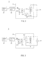
- FIG. 2 is a schematic illustration of the architecture of a light emitting device according to an embodiment of the invention.
- FIG. 3 is a schematic illustration of the architecture of another light emitting device according to the embodiment of the invention, wherein the first switch element and the LED are connected in parallel;
- FIG. 4 is a schematic illustration of the architecture of still another light emitting device according to the embodiment of the invention, which further includes a rectifier;
- FIG. 5 is a flow chart showing a calibrating method of the light emitting device according to the embodiment of the invention.
- FIG. 6 is a flow chart showing a control method of the light emitting device according to the embodiment of the invention.
- FIG. 7 is a flow chart of the step S 13 of FIG. 6 .
- a light emitting device 2 includes at least one LED unit 21, a memory unit 22 and a control unit 23.
- the light emitting device 2 can be a light bar or be applied to a backlight module or illumination.
- the LED unit 21 controls the lighting brightness thereof according to a brightness control signal S1.
- the LED unit 21 includes at least one LED 211, at least one first switch element 212, at least one energy-storage element 213 and at least one photo sense-control element 214.
- the first switch element 212 is electrically connected to the LED 211, and the first switch element 212 can be a BJT (Bipolar Junction Transistor) or an FET (Field Effect Transistor). In the embodiment, the first switch element 212 is, for example, a MOSFET (Metal-Oxide-Semiconductor Field-Effect Transistor). As shown in FIG. 2 , the first switch element 212 and the LED 211 can be connected in series. As shown in FIG. 3 , the first switch element 212 and the LED 211 can be connected in parallel.
- BJT Bipolar Junction Transistor
- FET Field Effect Transistor
- MOSFET Metal-Oxide-Semiconductor Field-Effect Transistor
- the energy-storage element 213 is electrically connected to the first switch element 212 and stores the brightness control signal S1.
- the energy-storage element 213 can be a capacitor, and the brightness control signal S1 is a voltage form, which is stored in the capacitor.
- the brightness control signal S 1 can be different forms, such as a current form, stored in the energy-storage element 213.
- the photo sense-control element 214 which is electrically connected to the energy-storage element 213, senses the illumination energy of the LED 211 and then adjusts the brightness control signal S1 according to the illumination energy. Then, the first switch element 212 is tuned on/off according to the value of the brightness control signal S1 stored in the energy-storage element 213, thereby enabling or disabling the LED 211. In this case, the first switch element 212 is tuned on/off according to the obvious changes of the value of the brightness control signal S1.
- the photo sense-control element 214 includes a photo diode and is connected with the energy-storage element 213 in parallel.
- the photo sense-control element 214 may include a control circuit (not shown), which is connected to the photo diode for achieving additional control.
- electrically connect can be directly or indirectly electrically connect.
- indirectly electrically connect means that two elements are electrically connected through an additional element.
- the memory unit 22 stores an initial relation of the brightness control signal S1 and the lighting brightness of the LED unit 21.
- the initial relation is a measured relation between the brightness control signal S 1 and the lighting brightness of each LED unit after the light emitting device 2 is manufactured.
- the initial relation can be concluded and be represented by a mathematic function or by a comparison table so as to show that different lighting brightness corresponds to different brightness control signal S1.
- the memory unit 22 is a non-volatile memory.
- the control unit 23 is electrically connected to the LED unit 21 and the memory unit 22. In the embodiment, the control unit 23 determines a value of the brightness control signal S1 according to a brightness required signal and the initial relation.
- the light emitting device 2 can further include a power supplier 24 for providing a DC power or an AC power to the LED 211. As shown in FIG. 4 , if the power supplier 24 provides an AC power, the light emitting device 2 further includes a rectifier 25, which can be a full-bridge rectifier, for transforming the AC power into a DC power, which is then provided to the LED 211.
- a power supplier 24 for providing an AC power
- the light emitting device 2 further includes a rectifier 25, which can be a full-bridge rectifier, for transforming the AC power into a DC power, which is then provided to the LED 211.
- the LED units 21 can be individually controlled. However, since the coupling coefficients of the LED units 21 are different, the errors may be generated during controlling.
- the calibrating method of the light emitting device according to the embodiment of the invention will be described herein below with reference to FIG. 5 .
- the calibrating method of the light emitting device includes the following steps S01 to S03.
- Step S01 is to input a brightness control signal to the LED unit 21.
- the LEDs of the LED unit 21 can emit light according to the brightness control signal.
- Steps S02 is to measure a lighting brightness of the LED unit.
- the lighting brightness is an average brightness of the LEDs.
- Step S03 is to write an initial relation of the brightness control signal and the lighting brightness into a memory unit.
- the initial relation can be concluded and represented by a mathematic function or a comparison table.
- a control method of the light emitting device which includes the steps S11 to S13, can be performed as shown in FIG. 6 .
- Step S11 is to read the initial relation from the memory unit.
- Step S12 is to determine a value of the brightness control signal for the LED unit according to a brightness requirement and the initial relation.
- Step S13 is to input the brightness control signal to the LED unit.
- the light emitting device can be the above-mentioned light emitting device 2.
- the step S13 further includes the steps S131 to S133.
- Step S131 is to input the brightness control signal to the energy-storage element.
- Step S 132 is to control the first switch element according to the brightness control signal so as to enable the LED to emit light.
- Step S133 is to enable the photo sense-control element to sense the illumination energy of the LED and to adjust the brightness control signal stored in the energy-storage element.
- the lighting brightness of the LEDs is controlled by the brightness control signal with different values, and the valud of the brightness control signal can be determined according to the initial relation and the required light brightness of the light emitting device.
- the light emitting device can control the first switch element according to the brightness control signal so as to disable the LEDs.
- the initial relation between the brightness control signal and the lighting brightness of the light emitting device is stored in the memory unit in advance.
- the light emitting device can obtain the corresponding brightness control signal by the calculation or table lookup method according to the initial relation after receiving the required lighting brightness.
- the LED unit of the light emitting device can be driven according to the brightness control signal. Accordingly, when there are multiple LED units, the lighting, brightness of the LED units can be adjusted to be the same according to the corresponding initial relations.
- a calibrating method of a light emitting device which includes at least one light-emitting diode (LED) unit.
- the calibrating method includes the steps of inputting a brightness control signal to the LED unit, measuring a lighting brightness of the LED unit, and writing an initial relation of the brightness control signal and the lighting brightness into a memory unit.
- a light emitting device and a controlling method thereof are also disclosed.
Landscapes
- Circuit Arrangement For Electric Light Sources In General (AREA)
- Control Of El Displays (AREA)
- Control Of Indicators Other Than Cathode Ray Tubes (AREA)
- Arrangement Of Elements, Cooling, Sealing, Or The Like Of Lighting Devices (AREA)
Applications Claiming Priority (1)
| Application Number | Priority Date | Filing Date | Title |
|---|---|---|---|
| TW096126447A TW200906221A (en) | 2007-07-19 | 2007-07-19 | Light emitting device and its calibrating and controlling method |
Publications (2)
| Publication Number | Publication Date |
|---|---|
| EP2018089A2 true EP2018089A2 (de) | 2009-01-21 |
| EP2018089A3 EP2018089A3 (de) | 2009-09-02 |
Family
ID=39884480
Family Applications (1)
| Application Number | Title | Priority Date | Filing Date |
|---|---|---|---|
| EP08159979A Withdrawn EP2018089A3 (de) | 2007-07-19 | 2008-07-09 | Lichtemittierende Vorrichtung und Verfahren zu ihrer Kalibrierung und Steuerung |
Country Status (4)
| Country | Link |
|---|---|
| US (1) | US20090020685A1 (de) |
| EP (1) | EP2018089A3 (de) |
| JP (1) | JP2009026759A (de) |
| TW (1) | TW200906221A (de) |
Cited By (13)
| Publication number | Priority date | Publication date | Assignee | Title |
|---|---|---|---|---|
| US7826698B1 (en) | 2007-12-19 | 2010-11-02 | Oree, Inc. | Elimination of stitch artifacts in a planar illumination area |
| US7929816B2 (en) | 2007-12-19 | 2011-04-19 | Oree, Inc. | Waveguide sheet containing in-coupling, propagation, and out-coupling regions |
| US8128272B2 (en) | 2005-06-07 | 2012-03-06 | Oree, Inc. | Illumination apparatus |
| US8215815B2 (en) | 2005-06-07 | 2012-07-10 | Oree, Inc. | Illumination apparatus and methods of forming the same |
| US8231237B2 (en) | 2008-03-05 | 2012-07-31 | Oree, Inc. | Sub-assembly and methods for forming the same |
| US8272758B2 (en) | 2005-06-07 | 2012-09-25 | Oree, Inc. | Illumination apparatus and methods of forming the same |
| US8301002B2 (en) | 2008-07-10 | 2012-10-30 | Oree, Inc. | Slim waveguide coupling apparatus and method |
| US8328406B2 (en) | 2009-05-13 | 2012-12-11 | Oree, Inc. | Low-profile illumination device |
| US8591072B2 (en) | 2011-11-16 | 2013-11-26 | Oree, Inc. | Illumination apparatus confining light by total internal reflection and methods of forming the same |
| US8624527B1 (en) | 2009-03-27 | 2014-01-07 | Oree, Inc. | Independently controllable illumination device |
| US8727597B2 (en) | 2009-06-24 | 2014-05-20 | Oree, Inc. | Illumination apparatus with high conversion efficiency and methods of forming the same |
| US9164218B2 (en) | 2008-07-10 | 2015-10-20 | Oree, Inc. | Slim waveguide coupling apparatus and method |
| US9857519B2 (en) | 2012-07-03 | 2018-01-02 | Oree Advanced Illumination Solutions Ltd. | Planar remote phosphor illumination apparatus |
Families Citing this family (7)
| Publication number | Priority date | Publication date | Assignee | Title |
|---|---|---|---|---|
| TWI482951B (zh) * | 2010-01-22 | 2015-05-01 | Htc Corp | 電子裝置及光感測器的校準方法 |
| TWI490674B (zh) * | 2012-12-25 | 2015-07-01 | Hergy Lighting Technology Corp | 智慧型發光二極體驅動裝置 |
| US20150225151A1 (en) * | 2014-02-11 | 2015-08-13 | Christopher L. Osborn | Anti-Scalping Transdermal Patch Packaging Film |
| WO2017083725A1 (en) * | 2015-11-11 | 2017-05-18 | Luminara Worldwide, Llc | Systems and methods for reducing energy requirements of an electric light |
| US11615740B1 (en) | 2019-12-13 | 2023-03-28 | Meta Platforms Technologies, Llc | Content-adaptive duty ratio control |
| US11922892B2 (en) | 2021-01-20 | 2024-03-05 | Meta Platforms Technologies, Llc | High-efficiency backlight driver |
| CN115720395B (zh) * | 2022-12-30 | 2025-07-29 | 马瑞利汽车电子(广州)有限公司 | 一种灯光亮度校准方法 |
Family Cites Families (9)
| Publication number | Priority date | Publication date | Assignee | Title |
|---|---|---|---|---|
| JP3766042B2 (ja) * | 2002-06-21 | 2006-04-12 | 三菱電機株式会社 | ディスプレイ装置用背面光源及び液晶ディスプレイ装置 |
| JP2005019226A (ja) * | 2003-06-26 | 2005-01-20 | Calsonic Kansei Corp | 表示照明制御装置 |
| JP2006029896A (ja) * | 2004-07-14 | 2006-02-02 | Casio Comput Co Ltd | 照明装置及び発光素子の駆動回路 |
| JP4286801B2 (ja) * | 2005-03-11 | 2009-07-01 | 株式会社ナナオ | 発光装置、発光強度調整方法及び液晶表示装置 |
| DE102005018175A1 (de) * | 2005-04-19 | 2006-10-26 | Patent-Treuhand-Gesellschaft für elektrische Glühlampen mbH | LED-Modul und LED-Beleuchtungseinrichtung mit mehreren LED-Modulen |
| WO2007019663A1 (en) * | 2005-08-17 | 2007-02-22 | Tir Technology Lp | Digitally controlled luminaire system |
| JP2007141799A (ja) * | 2005-11-22 | 2007-06-07 | Nec Lcd Technologies Ltd | 面照明光源、該面照明光源に用いられる輝度補正回路及び輝度補正方法 |
| EP1958483B1 (de) * | 2005-12-01 | 2012-06-13 | Martin Professional A/S | Verfahren und vorrichtung zur steuerung einer lichtquelle mit variabler farbe |
| US7800876B2 (en) * | 2006-01-09 | 2010-09-21 | Microsemi Corp. - Analog Mixed Signal Group Ltd. | Fault detection mechanism for LED backlighting |
-
2007
- 2007-07-19 TW TW096126447A patent/TW200906221A/zh unknown
-
2008
- 2008-07-03 US US12/167,894 patent/US20090020685A1/en not_active Abandoned
- 2008-07-09 EP EP08159979A patent/EP2018089A3/de not_active Withdrawn
- 2008-07-15 JP JP2008183527A patent/JP2009026759A/ja active Pending
Cited By (22)
| Publication number | Priority date | Publication date | Assignee | Title |
|---|---|---|---|---|
| US8215815B2 (en) | 2005-06-07 | 2012-07-10 | Oree, Inc. | Illumination apparatus and methods of forming the same |
| US8128272B2 (en) | 2005-06-07 | 2012-03-06 | Oree, Inc. | Illumination apparatus |
| US8641254B2 (en) | 2005-06-07 | 2014-02-04 | Oree, Inc. | Illumination apparatus |
| US8272758B2 (en) | 2005-06-07 | 2012-09-25 | Oree, Inc. | Illumination apparatus and methods of forming the same |
| US8414174B2 (en) | 2005-06-07 | 2013-04-09 | Oree, Inc. | Illumination apparatus |
| US8459856B2 (en) | 2007-12-19 | 2013-06-11 | Oree, Inc. | Planar white illumination apparatus |
| US8064743B2 (en) | 2007-12-19 | 2011-11-22 | Oree, Inc. | Discrete light guide-based planar illumination area |
| US8172447B2 (en) | 2007-12-19 | 2012-05-08 | Oree, Inc. | Discrete lighting elements and planar assembly thereof |
| US8182128B2 (en) | 2007-12-19 | 2012-05-22 | Oree, Inc. | Planar white illumination apparatus |
| US7929816B2 (en) | 2007-12-19 | 2011-04-19 | Oree, Inc. | Waveguide sheet containing in-coupling, propagation, and out-coupling regions |
| US7826698B1 (en) | 2007-12-19 | 2010-11-02 | Oree, Inc. | Elimination of stitch artifacts in a planar illumination area |
| US8550684B2 (en) | 2007-12-19 | 2013-10-08 | Oree, Inc. | Waveguide-based packaging structures and methods for discrete lighting elements |
| US8231237B2 (en) | 2008-03-05 | 2012-07-31 | Oree, Inc. | Sub-assembly and methods for forming the same |
| US8301002B2 (en) | 2008-07-10 | 2012-10-30 | Oree, Inc. | Slim waveguide coupling apparatus and method |
| US9164218B2 (en) | 2008-07-10 | 2015-10-20 | Oree, Inc. | Slim waveguide coupling apparatus and method |
| US8624527B1 (en) | 2009-03-27 | 2014-01-07 | Oree, Inc. | Independently controllable illumination device |
| US8328406B2 (en) | 2009-05-13 | 2012-12-11 | Oree, Inc. | Low-profile illumination device |
| US8727597B2 (en) | 2009-06-24 | 2014-05-20 | Oree, Inc. | Illumination apparatus with high conversion efficiency and methods of forming the same |
| US8591072B2 (en) | 2011-11-16 | 2013-11-26 | Oree, Inc. | Illumination apparatus confining light by total internal reflection and methods of forming the same |
| US8840276B2 (en) | 2011-11-16 | 2014-09-23 | Oree, Inc. | Illumination apparatus confining light by total internal reflection and methods of forming the same |
| US9039244B2 (en) | 2011-11-16 | 2015-05-26 | Oree, Inc. | Illumination apparatus confining light by total internal reflection and methods of forming the same |
| US9857519B2 (en) | 2012-07-03 | 2018-01-02 | Oree Advanced Illumination Solutions Ltd. | Planar remote phosphor illumination apparatus |
Also Published As
| Publication number | Publication date |
|---|---|
| JP2009026759A (ja) | 2009-02-05 |
| TW200906221A (en) | 2009-02-01 |
| US20090020685A1 (en) | 2009-01-22 |
| EP2018089A3 (de) | 2009-09-02 |
Similar Documents
| Publication | Publication Date | Title |
|---|---|---|
| US20090020685A1 (en) | Light emitting device and its calibrating and control methods | |
| US8144111B2 (en) | Light emitting diode driving circuit having voltage detection | |
| US7057359B2 (en) | Method and apparatus for controlling driving current of illumination source in a display system | |
| JP4951369B2 (ja) | 照明装置及び照明システム | |
| US8242697B2 (en) | Light emitting diode street lamp with sensors | |
| US9210747B2 (en) | Driver for driving LED backlight source, LED backlight source and LCD device | |
| US20070200513A1 (en) | Drive device of color led backlight | |
| US20200008279A1 (en) | Light emitting diode thermal foldback control device and method | |
| CN102939793A (zh) | 具有管芯到管芯变化和温度漂移补偿的led控制器 | |
| EP2680669A1 (de) | Lichtemittierende Diodenansteuervorrichtung, Ansteuerverfahren einer lichtemittierenden Diode und computerlesbares Aufzeichnungsmedium | |
| US8259097B2 (en) | Backlight assembly, display comprising the same and control method thereof | |
| US8466625B2 (en) | Illumination device and method controlling the same | |
| KR20120124840A (ko) | 발광 다이오드 구동 장치 및 발광 다이오드 구동 방법 | |
| CN101169920A (zh) | 显示设备及其控制方法 | |
| TW200829082A (en) | LED driving circuit | |
| CN107256697A (zh) | 背光驱动电路 | |
| KR20130024182A (ko) | Led구동장치 | |
| US7589479B2 (en) | Backlight driving apparatus of liquid crystal display and method for driving backlight driving apparatus | |
| KR102358203B1 (ko) | Led 구동 장치, 방법 | |
| US20160374165A1 (en) | Backlight module and liquid-crystal display device using the same | |
| KR20140064519A (ko) | 발광 다이오드 구동 장치 | |
| CN101441856B (zh) | 背光模块及控制背光模块的亮度的方法 | |
| CN101355839A (zh) | 发光装置及其校正与控制方法 | |
| KR101511128B1 (ko) | 발광 다이오드의 구동방법, 이를 수행하기 위한 백라이트 어셈블리 및 이를 갖는 표시장치 | |
| KR20120070421A (ko) | Led구동 장치 및 방법 |
Legal Events
| Date | Code | Title | Description |
|---|---|---|---|
| PUAI | Public reference made under article 153(3) epc to a published international application that has entered the european phase |
Free format text: ORIGINAL CODE: 0009012 |
|
| AK | Designated contracting states |
Kind code of ref document: A2 Designated state(s): AT BE BG CH CY CZ DE DK EE ES FI FR GB GR HR HU IE IS IT LI LT LU LV MC MT NL NO PL PT RO SE SI SK TR |
|
| AX | Request for extension of the european patent |
Extension state: AL BA MK RS |
|
| PUAL | Search report despatched |
Free format text: ORIGINAL CODE: 0009013 |
|
| AK | Designated contracting states |
Kind code of ref document: A3 Designated state(s): AT BE BG CH CY CZ DE DK EE ES FI FR GB GR HR HU IE IS IT LI LT LU LV MC MT NL NO PL PT RO SE SI SK TR |
|
| AX | Request for extension of the european patent |
Extension state: AL BA MK RS |
|
| STAA | Information on the status of an ep patent application or granted ep patent |
Free format text: STATUS: THE APPLICATION IS DEEMED TO BE WITHDRAWN |
|
| 18D | Application deemed to be withdrawn |
Effective date: 20100303 |