EP2018329B1 - Verschluss mit angelenktem deckel für flaschen und dergleichen mit einem automatischen deckelöffnungssystem - Google Patents
Verschluss mit angelenktem deckel für flaschen und dergleichen mit einem automatischen deckelöffnungssystem Download PDFInfo
- Publication number
- EP2018329B1 EP2018329B1 EP07725224A EP07725224A EP2018329B1 EP 2018329 B1 EP2018329 B1 EP 2018329B1 EP 07725224 A EP07725224 A EP 07725224A EP 07725224 A EP07725224 A EP 07725224A EP 2018329 B1 EP2018329 B1 EP 2018329B1
- Authority
- EP
- European Patent Office
- Prior art keywords
- lid
- main body
- elastic element
- area
- closure according
- Prior art date
- Legal status (The legal status is an assumption and is not a legal conclusion. Google has not performed a legal analysis and makes no representation as to the accuracy of the status listed.)
- Not-in-force
Links
- 229920001971 elastomer Polymers 0.000 claims abstract description 40
- 239000000806 elastomer Substances 0.000 claims abstract description 40
- 239000000463 material Substances 0.000 claims description 51
- 238000005304 joining Methods 0.000 claims description 40
- 238000004873 anchoring Methods 0.000 claims description 24
- 239000004033 plastic Substances 0.000 claims description 13
- 229920003023 plastic Polymers 0.000 claims description 13
- 238000003825 pressing Methods 0.000 claims description 10
- 230000009471 action Effects 0.000 claims description 7
- 230000007423 decrease Effects 0.000 claims description 3
- 239000007799 cork Substances 0.000 abstract 2
- 238000004519 manufacturing process Methods 0.000 description 8
- 239000000243 solution Substances 0.000 description 7
- 238000000034 method Methods 0.000 description 6
- 230000015556 catabolic process Effects 0.000 description 3
- 230000007246 mechanism Effects 0.000 description 3
- 230000008569 process Effects 0.000 description 3
- 230000003313 weakening effect Effects 0.000 description 3
- 230000008901 benefit Effects 0.000 description 2
- 229920002725 thermoplastic elastomer Polymers 0.000 description 2
- 239000004743 Polypropylene Substances 0.000 description 1
- 230000003213 activating effect Effects 0.000 description 1
- 230000004913 activation Effects 0.000 description 1
- 239000011248 coating agent Substances 0.000 description 1
- 238000000576 coating method Methods 0.000 description 1
- 230000008602 contraction Effects 0.000 description 1
- 230000008878 coupling Effects 0.000 description 1
- 238000010168 coupling process Methods 0.000 description 1
- 238000005859 coupling reaction Methods 0.000 description 1
- 230000005057 finger movement Effects 0.000 description 1
- 238000002347 injection Methods 0.000 description 1
- 239000007924 injection Substances 0.000 description 1
- 230000003993 interaction Effects 0.000 description 1
- 238000000465 moulding Methods 0.000 description 1
- -1 polypropylene Polymers 0.000 description 1
- 229920001155 polypropylene Polymers 0.000 description 1
- XLYOFNOQVPJJNP-UHFFFAOYSA-N water Substances O XLYOFNOQVPJJNP-UHFFFAOYSA-N 0.000 description 1
Images



Classifications
-
- B—PERFORMING OPERATIONS; TRANSPORTING
- B65—CONVEYING; PACKING; STORING; HANDLING THIN OR FILAMENTARY MATERIAL
- B65D—CONTAINERS FOR STORAGE OR TRANSPORT OF ARTICLES OR MATERIALS, e.g. BAGS, BARRELS, BOTTLES, BOXES, CANS, CARTONS, CRATES, DRUMS, JARS, TANKS, HOPPERS, FORWARDING CONTAINERS; ACCESSORIES, CLOSURES, OR FITTINGS THEREFOR; PACKAGING ELEMENTS; PACKAGES
- B65D47/00—Closures with filling and discharging, or with discharging, devices
- B65D47/04—Closures with discharging devices other than pumps
- B65D47/06—Closures with discharging devices other than pumps with pouring spouts or tubes; with discharge nozzles or passages
- B65D47/08—Closures with discharging devices other than pumps with pouring spouts or tubes; with discharge nozzles or passages having articulated or hinged closures
- B65D47/0804—Closures with discharging devices other than pumps with pouring spouts or tubes; with discharge nozzles or passages having articulated or hinged closures integrally formed with the base element provided with the spout or discharge passage
- B65D47/0828—Closures with discharging devices other than pumps with pouring spouts or tubes; with discharge nozzles or passages having articulated or hinged closures integrally formed with the base element provided with the spout or discharge passage and elastically biased towards the open position only
-
- B—PERFORMING OPERATIONS; TRANSPORTING
- B65—CONVEYING; PACKING; STORING; HANDLING THIN OR FILAMENTARY MATERIAL
- B65D—CONTAINERS FOR STORAGE OR TRANSPORT OF ARTICLES OR MATERIALS, e.g. BAGS, BARRELS, BOTTLES, BOXES, CANS, CARTONS, CRATES, DRUMS, JARS, TANKS, HOPPERS, FORWARDING CONTAINERS; ACCESSORIES, CLOSURES, OR FITTINGS THEREFOR; PACKAGING ELEMENTS; PACKAGES
- B65D47/00—Closures with filling and discharging, or with discharging, devices
- B65D47/04—Closures with discharging devices other than pumps
- B65D47/06—Closures with discharging devices other than pumps with pouring spouts or tubes; with discharge nozzles or passages
- B65D47/08—Closures with discharging devices other than pumps with pouring spouts or tubes; with discharge nozzles or passages having articulated or hinged closures
-
- B—PERFORMING OPERATIONS; TRANSPORTING
- B65—CONVEYING; PACKING; STORING; HANDLING THIN OR FILAMENTARY MATERIAL
- B65D—CONTAINERS FOR STORAGE OR TRANSPORT OF ARTICLES OR MATERIALS, e.g. BAGS, BARRELS, BOTTLES, BOXES, CANS, CARTONS, CRATES, DRUMS, JARS, TANKS, HOPPERS, FORWARDING CONTAINERS; ACCESSORIES, CLOSURES, OR FITTINGS THEREFOR; PACKAGING ELEMENTS; PACKAGES
- B65D2251/00—Details relating to container closures
- B65D2251/10—Details of hinged closures
- B65D2251/1016—Means for locking the closure in closed position
- B65D2251/1025—Integral locking elements penetrating in an opening, e.g. a flap through a slit, a hook in an opening
-
- B—PERFORMING OPERATIONS; TRANSPORTING
- B65—CONVEYING; PACKING; STORING; HANDLING THIN OR FILAMENTARY MATERIAL
- B65D—CONTAINERS FOR STORAGE OR TRANSPORT OF ARTICLES OR MATERIALS, e.g. BAGS, BARRELS, BOTTLES, BOXES, CANS, CARTONS, CRATES, DRUMS, JARS, TANKS, HOPPERS, FORWARDING CONTAINERS; ACCESSORIES, CLOSURES, OR FITTINGS THEREFOR; PACKAGING ELEMENTS; PACKAGES
- B65D2251/00—Details relating to container closures
- B65D2251/10—Details of hinged closures
- B65D2251/1016—Means for locking the closure in closed position
- B65D2251/1033—Protuberances and cavities provided on a horizontal flange respectively of the container or base and the closure, and penetrating one into the other, e.g. of the press-button type
-
- B—PERFORMING OPERATIONS; TRANSPORTING
- B65—CONVEYING; PACKING; STORING; HANDLING THIN OR FILAMENTARY MATERIAL
- B65D—CONTAINERS FOR STORAGE OR TRANSPORT OF ARTICLES OR MATERIALS, e.g. BAGS, BARRELS, BOTTLES, BOXES, CANS, CARTONS, CRATES, DRUMS, JARS, TANKS, HOPPERS, FORWARDING CONTAINERS; ACCESSORIES, CLOSURES, OR FITTINGS THEREFOR; PACKAGING ELEMENTS; PACKAGES
- B65D2251/00—Details relating to container closures
- B65D2251/10—Details of hinged closures
- B65D2251/1066—Actuating means
Definitions
- the invention relates to the field of closures with hinged lids for bottles and the like.
- the invention relates to a closure with a hinged lid for bottles and the like having an automatic lid opening system, said closure comprising:
- documents EP0826606 , EP0839735 and EP0975526 describe a closure of the type described at the beginning.
- a first characteristic of this closure is that the elastic element made from elastomer material extends over the lid and the main body covering the anchoring means, so that said anchoring means are pleasant to touch when the user acts upon them to release them.
- This solution suffers from the drawback that an additional amount of elastomer material is required that must be moulded according to a relatively complicated shape, which has a negative affect on the closure's manufacturing cost.
- these anchoring means combined with the elastomer material do not form a button in the strict sense.
- a second characteristic of the closure disclosed by said documents EP0826606 , EP0839735 and EP0975526 is that the elastic element has an extendible section that passes from one side to the other of the hinge joint when the lid pivots between its open and hinged positions. Consequently, said extendible section is extended to the maximum when the lid is in an intermediate position, whereby the lid has two rest positions: the open position and the hinged position.
- the lid When the lid is in the hinged position and the user wants to open it, he must release the anchoring means and push the lid against the force of the elastic element, beyond the intermediate position.
- This mode of operation suffers from the drawback that it complicates the lid opening operation for the user, and does not open the lid automatically and completely with one simple pressing action.
- a third characteristic of the closure disclosed in said documents EP0826606 , EP0839735 and EP0975526 is that, in addition to forming an extendible section on level with the hinge joint so as to produce a spring-back function for the lid, the elastomer material also extends over part of the lid to ensure the seal of the supply hole.
- the elastomer material extends over the outer wall of a pin that is provided on the lid and which is forcibly inserted into the supply mouth, whereby the elastomer material is compressed between the outer wall of the pin and the inner wall of the supply mouth.
- Document EP0976663 discloses a closure of the type considered at the beginning, but which is different to the closure disclosed in the said documents EP0826606 , EP0839735 and EP0975526 because the lid's only rest position is the open position, which corresponds to a minimum extension of the extendible section of the elastic element.
- This mode of operation is obtained by virtue of the elastic element having an extendible section that is arranged between two ribs that form the hinge joint, and is joined to said ribs, so that said extendible section cannot pass freely from one side to the other of the hinge joint.
- the closure comprises an elastic button made from the elastomer material.
- the lid is provided with a pin that is inserted into said supply mouth, but contrary to the closures cited above, the elastomer material does not extend over the pin, instead it forms the top edge of the supply mouth on the main body.
- the extendible section of the elastic element must exert a strong spring-back force.
- said extendible section has limited elasticity, since it is attached to the ribs forming the hinge joint. Consequently, the lid's opening movement is fairly abrupt, which is not very pleasant for the user.
- the design of the push button formed by the elastomer material has a negative affect on the closure's manufacturing costs.
- Document JP8113260 relates to a closure that resembles the type of closure referenced in the invention, but wherein the anchoring means are not released by means of a button, but rather by traditional means, pulling a visor provided on the lid.
- the elastomer material only performs the lid's spring-back function, and it consists of a separate part that fits at its ends into housings provided in the lid and in the main body of the closure, and has an intermediate extendible section that is freely positioned externally with respect to the hinge joint.
- the lid's only rest position is the open position, which corresponds to a maximum extension of the extendible section.
- Document W02004110889 discloses a type of closure in which the hinge joint is made from the actual elastic element arranged as a single connection means between the lid and the main body.
- This solution is different to the type of closure described in the invention and suffers from the drawback that it considerably complicates closure manufacturing.
- the closure does not comprise anchoring means in the strict sense; the function of maintaining the lid in its hinged position is carried out by the actual pin provided on the lid, which is inserted into the supply mouth to seal it and remains fixed therein by virtue of friction.
- the closure is provided with a button that is operated by pressing the lid upwards until the pin withdraws from the supply mouth.
- This opening system suffers from the drawback that the user must act upon the button, moving it sufficiently to remove the pin from the supply mouth. This is not very comfortable and differs from the operation of a proper button, which must act instantly.
- EP1582476A discloses a closure according to the preamble of claim 1, in which an automatic opening mechanism of the lid is provided by compressing an elastic element which is jammed between the inner face of the lid and a stop block provided in the main body of the closure.
- an automatic opening mechanism of the lid is provided by compressing an elastic element which is jammed between the inner face of the lid and a stop block provided in the main body of the closure.
- the aim of the invention is to provide a closure of the type indicated at the beginning, which has an alternative hinge contruction for the self-opening mechanism.
- the main aim of the invention is to provide a closure wherein the design of the elastic element, as well as the closure parts interacting with said elastic element, provides an improved automatic lid opening action, in particular a more effective opening action that is not too abrupt, and which does not negatively affect the closure manufacturing costs and does not excessively compromise the freedom of the closure's aesthetic design.
- This arrangement ensures that the extendible section of the elastic element is always positioned externally with respect to the hinge joint, whereby the lid's only rest position is the open position that corresponds to a minimum extension of the elastic element's extendible section.
- the extendible section is arranged freely opposite the seating surface, its elasticity is not affected by interference with the rigid elements of the closure.
- providing said projection on the main body of the closure maintains the freedom of the lid's design, making particularly advantageous solutions possible.
- One of these advantageous solutions consists in the projection defining the seating surface extending from a lower end of the main body next to said first joining area of the elastic element, to an upper end that projects from said main body and that is next to said second joining area of the elastic element when the lid is in its hinged position.
- said seating surface has a convex shaped section on which the elastic element's extendible section rests in the lid's hinged position, therefore providing gentle support that prevents localised tension.
- said second joining area of the elastic element has an elongated shape that extends parallel to the axis of said hinge joint, and said elastic element has two of said first joining areas, separated by an open space facing said hinge joint, and two of said free extendible sections defined between said first joining areas and said second joining area, said main body comprising two of said projections that respectively define two of said seating surfaces positioned externally with respect to the hinge joint and respectively facing said two extendible sections of the elastic element.
- said main body and said lid have a contour that is truncated by respective flat surfaces joined by a bridge that forms said hinge joint, said projection protruding from the flat surface of the main body, and said flat surface of the lid having at least one window through which said projection and said extendible section of the elastic element protrude when the lid is in the hinged position.
- the invention contemplates, optionally, some advantageous embodiments including characteristics regarding the button. These characteristics, in combination with those described above regarding the elastic element and the parts of the closure interacting with it, make it possible to obtain a closure having a button that acts quickly releasing the anchoring means between the lid and the main body, efficiently opening the lid, and without it being necessary to use elastomer material to form the button and without significantly complicating the manufacturing process.
- the main body has a side wall and an upper base on which the supply mouth is provided;
- the button is made up of a moveable area that is moulded as an integral part of said main body in rigid plastics material and has at least one front portion delimited on said side wall and joined at its lower end to said side wall by a joining line that defines a pivoting axis of said movable area, said front portion having a pressing surface suitable for receiving a user's finger;
- the anchoring means comprise a first part formed in said movable area and a second part formed on said lid and suitable for anchoring in said first part.
- This closure according to the invention does not require using elastomer material to form the button; it is based on local geometric forms defined in the actual rigid plastics material of the main body and the lid. Moreover, thanks to the fact that the first part of said anchoring means is provided in the movable area of the main body, when the button is activated, the second part of the anchoring means are released directly and the lid is opened.
- the surface for activating the button is located in the actual movable area, whereby the user acts directly on the movable area.
- This direct activation and release combined with the spring-back force exerted by the elastic element provided between the lid and the main body, easily and effectively opens the lid.
- the user acts upon the pressing surface defined on the front portion of the button, in other words on the side wall of the main body, so that the lid can be opened comfortably with one simple finger movement, while holding the bottle in one hand.
- said movable area is delimited on said main body by a deformable contour defined by a geometric weakening of the actual wall of said main body.
- This deformable contour makes the button more robust and, since it is deformable, allows the movable area limited but sufficient pivoting around the joining line.
- the geometric weakening of the wall of the main body that forms said deformable contour has, in section, a toggled shape and a reduced thickness with respect to the adjacent areas of said wall.
- the deformable contour can be slightly stretched and contracted, allowing the movable area sufficient movement to release the anchoring means.
- this geometric arrangement can be obtained easily during the moulding operation for the closure's main body.
- said deformable contour has an upper section that defines in said upper base an upper part of the movable area and respective side sections that define in said side wall the front portion of the movable area, said side sections extending the ends of said upper section as far as said joining line.
- said geometric weakening forms said deformable contour in the shape of a groove the depth of which decreases in said side sections towards the lower ends thereof, which reinforces the button without considerably affecting the pivoting of the deformable area around the joining line.
- the anchoring means consist of a window in said front portion of the movable area and a hook-shaped projection formed on the lid.
- the moveable area is moved away from the side wall thereby unhooking the projection from the window.
- said deformable contour defines a continuous joining surface between said movable area and the rest of said main body, thereby preventing dirt or any external element from entering through the deformable contour.
- the invention also contemplates, optionally, some advantageous embodiments including characteristics regarding the lid's seal of the supply mouth. These characteristics are intended to provide a closure wherein the interaction between the lid and the supply mouth does not produce significant friction between these elements, so that when the anchoring means are released by acting upon the button, the lid opens without any impediment, stretched by the spring-back action of the elastic element, without the latter having to exert any significant force to unblock the supply mouth.
- said lid is provided on its inner surface with a flat contact area made from elastomer material and facing said supply mouth in the lid's hinged position, so that said flat contact area of the elastic element is applied against the upper edge of said supply mouth.
- This flat contact area made from elastomer material ensures the supply mouth has an airtight seal, without any outer or inner coupling with the supply mouth, whereby said supply mouth is unblocked simply by lifting the lid, without it being necessary to overcome any strong friction force.
- the inner surface of said lid has a hollow area that houses said flat contact area, and makes it easier to join it to the lid when manufacturing the closure.
- said elastic element made from elastomer material that ensures the lid's spring-back action, also forms said flat contact area. This avoids having different pieces of elastomer material and facilitates the closure manufacture process by overmoulding the elastomer material over the rigid plastics material of the main body and the lid.
- said elastic element comprises a connection strip that extends between said flat contact area and the part of the elastic element where the second joining area is provided, and the inner surface of said lid has a channel that leads into said hollow area and houses said connection strip.
- this solution facilitates forming the elastic element made from elastomer material with an overmoulding method, because the channel and the hollow area act as a mould.
- said flat contact area and said connection strip are arranged level with said hollow area and said channel, respectively, thereby preventing any projections on the inner surface of the lid where dirt could accumulate.
- the elastic element made from elastomer material is overmoulded on the piece of rigid plastics material made up of said main body and said lid, for example using a bi-injection method.
- said elastic element goes through the thickness of said lid from said contact area and forms an outer layer of elastomer material that extends over at least part of the lid's outer surface. This way the elastomer material can be injected over the lid's outer surface and, at the same time, an outer coating of elastomer material can be obtained that is suitable for forming a publicity or geometric motif that personalises the closure.
- Figs. 1 to 13 illustrate a first embodiment of a closure according to the invention, which is intended to be applied to bottles of water and which enables the lid to be opened easily with the same hand that is holding the bottle, by using a finger to press a button provided on the closure's main body.
- the closure is made up of a main body 1, which has a supply mouth 2, and a lid 3 that is joined to the main body 1 by a bridge 4 that performs the functions of a hinge joint.
- Main body 1 and lid 3 are moulded as an integral part in a rigid plastics material, for example polypropylene. Lid 3 can pivot with respect to the axis formed by the hinge joint 4 between an open position and a hinged position wherein lid 3 blocks supply mouth 2.
- TPE thermoplastic elastomer
- Elastic element 7 has an extendible section 7c freely positioned externally with respect to hinge joint 4, so that when lid 3 is closed, making it pivot from its open position, extendible section 7c gradually becomes tenser and therefore always exerts a spring-back force on lid 3 towards its open position.
- elastic element 7 has two joining areas 7a integral with main body 1 and one second joining area 7b integral with lid 3. Between the first joining areas 7a and the second joining area 7b respective extendible sections 7c of the elastic element are provided, which are freely positioned externally with respect to hinge joint 4. The first joining areas are separated by an open space 23 that faces said hinge joint 4.
- Main body 1 comprises two projections 9 that define seating surfaces 10 positioned externally with respect to hinge joint 4 and face the elastic element's extendible sections 7c.
- Each projection 9 extends from a lower end located on main body 1, next to a first joining area 7a of the elastic element, to an upper end that projects from main body 1 and is located next to the second joining area 7b of the elastic element in the lid's hinged position 3.
- Surface 10 formed on each projection 9 has a convex shaped section at the top thereof, whereas the lower part is flat to facilitate mould stripping.
- Main body 1 and lid 3 have a contour that is truncated by respective flat surfaces 19, 20 joined by the bridge 4 that forms the hinge joint.
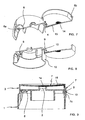
- Projections 9 project from flat surface 19 of the main body and flat surface 20 of the lid has respective windows 21 through which projections 9 and extendible sections 7c of elastic element 7 protrude in the hinged position of lid 3, as can be seen in Figs. 11 , 12 and 13 .
- Main body 1 has an overall cylindrical shape, with a side wall 11 and an upper base 12 in which supply mouth 2 is provided, and it has a movable area 5 delimited by a deformable contour 8 defined by a geometric weakness in the actual wall of main body 1, as can be seen in greater detail in Figs. 4 to 6 .
- the geometric weakness that shapes deformable contour 8 has, in section, a toggled shape and a reduced thickness with respect to the adjacent areas of the wall of main body 1, and defines a continuous joining surface between said movable area 5 and the rest of main body 1, as can be seen in particular in Figs. 7 to 9 .
- the thus formed deformable contour 8 has a U-shaped upper section 8a provided in upper base 12 of main body 1 and respective side sections 8b that extend into side wall 11 extending the ends of upper section 8a and defining in said side wall 11 a front portion 5a of movable area 5.
- the lower end of said front portion 5a, in to which the two side sections 8b lead, is joined to side wall 11 forming a joining line 22 around which movable area 5 pivots.
- the depth of the groove formed by the geometric weakness that shapes contour 8 decreases towards the lower ends of side sections 8a, as far as joining line 22.
- a pressing surface 13, suitable for receiving a user's finger, is provided on front portion 5a of movable area 5.
- the closure comprises anchoring means between lid 3 and main body 1 consisting of a window 6a in front portion 5a of movable area 5 and a hook-shaped projection 6b formed on lid 3.
- anchoring means between lid 3 and main body 1 consisting of a window 6a in front portion 5a of movable area 5 and a hook-shaped projection 6b formed on lid 3.
- the user pivots it by acting against the spring-back force of elastic element 7, until the lid reaches the hinged position shown in Fig. 9 , wherein projection 6b is anchored in window 6a.
- the thus formed movable area 5 forms a button suitable for operating the release of said anchoring means 6a, 6b and causing the subsequent automatic opening of lid 3.
- the user presses pressing surface 13 with his finger causing movable area 5 to pivot slightly, the top part of which moves away from wall 11, whereby projection 6b withdraws from window 6a and releases lid 3, which pivots to its open position thanks to the spring-back force exerted by elastic element 7.
- the pivoting of movable area 5 around joining line 22 is accompanied by a transverse contraction of upper section 8a and a sideways deformation of side sections 8b and the longitudinal sides of said upper section 8a.
- this embodiment of the closure according to the invention includes particular characteristics regarding the lid's airtight seal of the supply mouth.
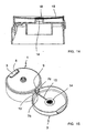
- Elastic element 7 made from elastomer material extends, from the part where the second joining area 7b is provided, along a connection strip 15 to form at the end of the latter a flat contact area 14 between lid 3 and supply mouth 2.
- the inner surface of lid 3 has a channel 16 that leads into said central hollow area 17.
- Elastic element 7 made from elastomer material is formed by an overmoulding method over the piece of rigid plastics material formed by main body 1 and lid 3, so that connection strip 15 and flat contact area 14 are provided on level; respectively, with said channel 16 and said hollow area 17.
- Fig. 9 in the hinged position of lid 3 flat contact area 14 made from elastomer material is applied against the upper edge of supply mouth 2, without being inserted therein through friction.
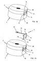
- Fig. 14 illustrates a second embodiment that is a variant of the first.
- lid 3 has a central hole through which the elastomer material is injected in the overmoulding process, so that elastic element 7 that is made from elastomer material and is formed by this process goes through the thickness of lid 3 from said flat contact area 14 and forms an outer layer 18 of elastomer material that extends over part of the outer surface of lid 3.
- the shape and appearance of said external layer 18 can be personalised for each closure.
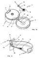
- FIGs. 15 to 17 illustrate a third embodiment of the invention wherein an elastic element 7 has been provided with a single joining area 7a joined to the second joining area 7b by a single extendible section 7c.
- Main body 1 has a single central projection 9.
- main body 1 and lid 3 do not have a contour that is truncated on level with hinge joint 4 as in the preceding embodiments, instead said contour is substantially circular.
- Hinge joint 4 is made up of two parts arranged on each side of central projection 9.
Landscapes
- Engineering & Computer Science (AREA)
- Mechanical Engineering (AREA)
- Closures For Containers (AREA)
Claims (19)
- Verschluss mit Klappdeckel für Flaschen und dergleichen, der ein automatisches Deckelöffnungssystem hat, wobei der Verschluss aufweist:einen mit einer Zuführöffnung (2) versehenen Hauptkörper (1), der zum Anbringen an den Hals einer Flasche oder dergleichen geeignet ist;einen Klappdeckel (3), der mit dem Hauptkörper (1) durch eine Gelenkverbindung (4) so verbunden ist, dass der Deckel (3) zwischen einer offenen Position und einer geklappten Position schwenken kann, in der er die Zuführöffnung (2) blokkiert; wobei der Hauptkörper (1) und der Deckel (3) aus starrem Kunststoffmaterial geformt sind;ein Federelement (7), das zwischen dem Hauptkörper (1) und dem Deckel (3) so angeordnet ist, dass es eine Rückstellkraft an den Deckel (3) in Richtung seiner geöffneten Position anlegt, wobei das Federelement (7) aus einem anderen Elastomermaterial ist als das starre Kunststoffmaterial;eine Verankerungseinrichtung (6a, 6b) zwischen dem Deckel (3) und dem Hauptkörper (1), die zum Halten des Deckels (3) in seiner geklappten Position geeignet ist; undeinen Druckknopf, der zum Auslösen der Freigabe der Verankerungseinrichtung (6a, 6b) geeignet ist, so dass durch Einwirken auf den Druckknopf der Deckel aufgrund der Wirkung der durch das Federelement (7) angelegten Rückstellkraft automatisch und vollständig geöffnet wird;wobei das Federelement (7) mindestens einen ersten fest an den Hauptkörper (1) angebrachten Verbindungsbereich (7a) und mindestens einen zweiten Verbindungsbereich (7b) hat, wobei mindestens ein zwischen dem ersten (7a) und dem zweiten (7b) Verbindungsbereich definierter dehnbarer Abschnitt (7c) des Federelements (7) vorhanden ist;der Hauptkörper (1) mindestens einen eine Auflagefläche (10) definierenden Vorsprung (9) enthält; undder dehnbare Abschnitt (7c) des Federelements (7) sich frei vor der Auflagefläche (10) erstreckt,so dass, wenn der Deckel (3) in Richtung seiner geklappten Position schwenkt, die Auflagefläche (10) den dehnbaren Abschnitt (7c) des Federelements (7) aufnimmt,dadurch gekennzeichnet, dassdie Auflagefläche (10) bezüglich der Gelenkverbindung (4) außerhalb positioniert ist;der zweite Verbindungsbereich (7b) fest an dem Deckel (3) angebracht ist, und der dehnbare Abschnitt (7c) des Federelements (7) auf der Auflagefläche (10) aufliegt, wenn der Deckel (3) in seiner geklappten Position ist, unddie Auflagefläche (10) den dehnbaren Bereich (7c) bezüglich der Gelenkverbindung (4) außerhalb positioniert hält.
- Verschluss nach Anspruch 1, dadurch gekennzeichnet, dass der Vorsprung (9) von einem am Hauptkörper (1), neben dem ersten Verbindungsbereich (7a) des Federelements (7) gelegenen, unteren Ende zu einem vom Hauptkörper (1) vorstehenden, neben dem zweiten Verbindungsbereich (7b) des Federelements (7) gelegenen, oberen Ende verläuft, wenn der Deckel (3) in seiner geklappten Position ist.
- Verschluss nach Anspruch 2, dadurch gekennzeichnet, dass die Auflagefläche (10) einen konvex geformten Abschnitt hat, auf dem der dehnbare Abschnitt (7c) des Federelements in der geklappten Position des Deckels (3) aufliegt.
- Verschluss nach Ansprüchen 1 bis 3, dadurch gekennzeichnet, dass der zweite Verbindungsbereich (7b) des Federelements (7) eine längliche Form hat, die parallel zur Achse der Gelenkverbindung (4) verläuft, und das Federelement (7) zwei der ersten Verbindungsbereiche (7a), die durch einen der Gelenkverbindung (4) zugewandten Freiraum (23) geteilt sind, und zwei der freien, dehnbaren Abschnitte (7c), die zwischen den ersten Verbindungsbereichen (7a) und dem zweiten Verbindungsbereich (7b) definiert sind, aufweist, wobei der Hauptkörper (1) zwei der Vorsprünge (9) enthält, die jeweils zwei der bezüglich zur Gelenkverbindung (4) außerhalb positionierten Auflageflächen (10) definieren und jeweils den zwei dehnbaren Abschnitten (7c) des Federelements zugewandt sind.
- Verschluss nach einem der Ansprüche 1 bis 4, dadurch gekennzeichnet, dass der Hauptkörper (1) und der Deckel (3) eine Kontur haben, die durch zugehörige flache Oberflächen (19, 20) abgeflacht ist, welche durch einen die Gelenkverbindung (4) erzeugenden Steg (4) verbunden sind, wobei der Vorsprung (9) entlang einer flachen Oberfläche (19) des Hauptkörpers (1) vorsteht und die flache Oberfläche (20) des Deckels (3) mindestens ein Fenster (21) hat, durch das der Vorsprung (9) und der dehnbare Abschnitt (7c) des Federelements (7) hervortreten, wenn der Deckel (3) in der geklappten Position ist.
- Verschluss nach einem der Ansprüche 1 bis 5, dadurch gekennzeichnet, dass:der Hauptkörper (1) eine Seitenwand (11) und eine obere Grundfläche (12) aufweist, an der die Zuführöffnung (2) vorgesehen ist;der Druckknopf aus einem beweglichen Bereich (5) ist, der einstückig mit dem Hauptkörper (1) aus starrem Kunststoffmaterial geformt ist, wobei der bewegliche Bereich (5) mindestens ein Vorderteil (5a) enthält, das an der Seitenwand (11) begrenzt ist und an seinem unteren Ende mit der seitenwand (11) durch eine eine Schwenkachse des beweglichen Bereichs (5) definierende Verbindunglinie (22) verbunden ist, wobei das Vorderteil (5a) eine Druckfläche (13) aufweist, die zur Aufnahme eines Fingers eines Benutzers geeignet ist; unddie Verankerungseinrichtung (6a, 6b) ein erstes in dem beweglichen Bereich (5) gebildetes Bauteil (6a) und ein in dem Deckel (3) gebildetes und zum Verankern in dem ersten Bauteil (6a) geeignetes zweites Bauteil (6b) enthält.
- Verschluss nach Anspruch 6, dadurch gekenntzeichnet, dass der bewegliche Bereich (5) an dem Hauptkörper (1) durch eine deformierbare Kontur (8) begrenzt ist, die durch eine geometrische Schwäche der eigentlichen Wand des Hauptkörpers (1) definiert ist.
- Verschluss nach Anspruch 7, dadurch gekennzeichnet, dass die die deformierbare Kontur (8) gestaltende geometrische Schwäche in der Wand des Hauptkörpers (1) eine im Schnitt hin- und herwechselnde Form und eine reduzierte Dicke bezüglich der angrenzenden Bereiche der Wand aufweist.
- Verschluss nach Ansprüchen 7 oder 8, dadurch gekennzeichnet, dass die deformierbare Kontur (8) einen oberen Abschnitt (8a) aufweist, der in der oberen Grundfläche (12) ein oberes Bauteil (5b) des beweglichen Bereichs (5) und entsprechende Seitenabschnitte (8b) definiert, die in der Seitenwand (11) das Vorderteil (5a) des bewegliches Bereichs (5) definieren, wobei die Seitenabschnitte (8b) die Enden des oberen Abschnitts (8a) bis zur Verbindungslinie (22) erweitern.
- Verschluss nach Ansprüchen 8 und 9, dadurch gekennzeichnet, dass die geometrische Schwäche die deformierbare Kontur (8) in der Form einer Kerbe gestaltet, die in den Seitenabschnitten (8b) eine in Richtung der unteren Enden der Seitenabschnitte (8b) abnehmende Tiefe aufweist.
- Verschluss nach einem der Ansprüche 6 bis 10, dadurch gekennzeichnet, dass die Verankerungseinrichtung (6a, 6b) aus einem im Vorderteil (5a) des beweglichen Bereichs (5) gebildeten Fenster (6a) und einem am Deckel (3) gebildeten hakenförmigen Vorsprung (6b) besteht.
- Verschluss nach einem der Ansprüche 7 bis 11, dadurch gekennzeichnet, dass die deformierbare Kontur (8) eine kontinuierliche Verbindungsfläche zwischen dem beweglichen Bereich (5) und dem Rest des Hauptkörpers (1) definiert.
- Verschluss nach einem der Ansprüche 1 bis 12, dadurch gekennzeichnet, dass der Deckel (3) an seiner Innenfläche einen flachen Kontaktbereich (14) aus Elastomermaterial aufweist, der der Zuführöffnung (2) in der geklappten Position des Deckels (3) so zugewandt ist, dass der flache Kontaktbereich (14) des Federelements gegen die obere Kante der Zuführöffnung (2) anliegt.
- Verschluss nach Anspruch 13, dadurch gekennzeichnet, dass die Innenfläche des Deckels (3) einen den flachen Kontaktbereich (14) aufnehmenden Hohlbereich (17) aufweist.
- Verschluss nach Ansprüchen 13 oder 14, dadurch gekennzeichnet, dass das Federelement (7) den flachen Kontaktbereich (14) bildet.
- Verschluss nach Anspruch 15, dadurch gekennzeichnet, dass das Federelement (7) einen Verbindungsstreifen (15) enthält, der zwischen dem flachen Kontaktbereich (14) und dem Bauteil des Federelements (7), an dem der zweite Verbindungsbereich (7b) vorgesehen ist, verläuft, und dadurch, dass die Innenfläche des Deckels (3) einen Kanal (16) aufweist, der zum Hohlbereich (17) führt und den Verbindungsstreifen (15) aufnimmt.
- Verschluss nach Anspruch 16, dadurch gekennzeichnet, dass der flache Kontaktbereich (14) und der Verbindungsstreifen (15) auf derselben Ebene mit dem Hohlbereich (17) beziehungsweise dem Kanal (16) vorgesehen sind.
- Verschluss nach Anspruch 16 oder 17, dadurch gekennzeichnet, dass das Federelement (7) aus Elastomermaterial über das den Hauptkörper (1) und den Deckel (3) bildende starre Kunststoffmaterial geformt ist.
- Verschluss nach Anspruch 18, dadurch gekennzeichnet, dass das Federelement (7) durch die Dicke des Deckels (3) von dem flachen Kontaktbereich (14) geht und eine mindestens über einen Teil der Außenfläche des Deckels (3) verlaufende Außenschicht (18) aus Elastomermaterial bildet.
Applications Claiming Priority (2)
| Application Number | Priority Date | Filing Date | Title |
|---|---|---|---|
| ES200601273A ES2262449B1 (es) | 2006-05-18 | 2006-05-18 | "tapon con tapa abatible para botellas y similares dotado de un sistema automatico de apertura de la tapa". |
| PCT/EP2007/004306 WO2007134755A1 (en) | 2006-05-18 | 2007-05-15 | Closure with hinged lid for bottles and the like with an automatic lid opening system |
Publications (2)
| Publication Number | Publication Date |
|---|---|
| EP2018329A1 EP2018329A1 (de) | 2009-01-28 |
| EP2018329B1 true EP2018329B1 (de) | 2011-07-13 |
Family
ID=37565126
Family Applications (1)
| Application Number | Title | Priority Date | Filing Date |
|---|---|---|---|
| EP07725224A Not-in-force EP2018329B1 (de) | 2006-05-18 | 2007-05-15 | Verschluss mit angelenktem deckel für flaschen und dergleichen mit einem automatischen deckelöffnungssystem |
Country Status (10)
| Country | Link |
|---|---|
| US (1) | US8127954B2 (de) |
| EP (1) | EP2018329B1 (de) |
| CN (1) | CN101448710B (de) |
| AT (1) | ATE516226T1 (de) |
| BR (1) | BRPI0711927B1 (de) |
| CA (1) | CA2652750A1 (de) |
| ES (2) | ES2262449B1 (de) |
| MX (1) | MX2008013784A (de) |
| RU (1) | RU2442731C2 (de) |
| WO (1) | WO2007134755A1 (de) |
Families Citing this family (29)
| Publication number | Priority date | Publication date | Assignee | Title |
|---|---|---|---|---|
| ES2262450B1 (es) * | 2006-05-18 | 2007-09-16 | Seaplast, S.A. | "tapon con tapa abatible para botellas y similares dotado de un sistema automatico de apertura de la tapa que comprende un pulsador mejorado". |
| US20080245795A1 (en) * | 2007-04-05 | 2008-10-09 | Berge Gary L | Auto open closure |
| ES2302664B1 (es) * | 2008-03-17 | 2009-08-06 | Seaplast S.A. | "tapon con tapa abatible para botellas y similares dotado de un sistema automatico mejorado de apertura de la tapa". |
| JP5352282B2 (ja) * | 2009-02-27 | 2013-11-27 | 大成化工株式会社 | キャップ及びキャップ付容器 |
| MX2013009400A (es) * | 2011-03-03 | 2013-09-26 | Aptargroup Inc | Cierre con caracteristicas a prueba de manipulacion. |
| BR302012003198S1 (pt) | 2012-01-02 | 2014-10-14 | Brita Gmbh | Configuração aplicada a garrafa de bebida |
| HUE028522T2 (en) * | 2012-02-28 | 2016-12-28 | Clariant Production (France) S A S | Container for receiving moisture sensitive items |
| EP2855298B1 (de) | 2012-05-29 | 2016-04-27 | Aptar Freyung GmbH | Ausgabeverschluss |
| US10329061B2 (en) | 2013-11-07 | 2019-06-25 | Thermos L.L.C. | System and methods for managing a container or its contents |
| USD780578S1 (en) * | 2014-08-14 | 2017-03-07 | Thermos L.L.C. | Lid |
| USD769715S1 (en) * | 2014-03-21 | 2016-10-25 | Clairant Production (France) SAS | Closure for a container |
| USD758790S1 (en) * | 2014-04-21 | 2016-06-14 | Thermos L.L.C. | Lid |
| WO2016111012A1 (ja) * | 2015-01-09 | 2016-07-14 | 富士通フロンテック株式会社 | 紙葉類格納装置及び紙葉類格納方法 |
| USD780579S1 (en) * | 2015-07-29 | 2017-03-07 | Cj Cheiljedang Corp. | Food container cap |
| USD779940S1 (en) * | 2015-07-29 | 2017-02-28 | Cj Cheiljedang Corp. | Food container cap |
| USD838592S1 (en) * | 2016-03-23 | 2019-01-22 | Tracey C Henderson | Lighted cap for a squeeze tube |
| USD818309S1 (en) * | 2016-06-14 | 2018-05-22 | Industrias Alen, S.A. De C.V. | Bottle cap |
| USD821136S1 (en) * | 2016-12-02 | 2018-06-26 | Pacific Market International, Llc | Beverage container lid |
| JP6767277B2 (ja) * | 2017-02-08 | 2020-10-14 | 株式会社ジーシー | ワンタッチ開封キャップ |
| US10561262B2 (en) | 2017-03-15 | 2020-02-18 | Pacific Market International, Llc | Beverage container with non-manual lid operation |
| GB2580246B (en) | 2017-08-31 | 2022-08-03 | Kimberly Clark Co | Container having a push-button activated, pop-open lid |
| US11292642B2 (en) | 2018-12-21 | 2022-04-05 | H. J. Heinz Company Brands Llc | Container, closure, and methods for manufacture |
| USD889260S1 (en) | 2018-12-21 | 2020-07-07 | H.J. Heinz Company Brands Llc | Closure for a container |
| EP4368284A3 (de) | 2018-12-21 | 2024-08-14 | H.J. Heinz Company Brands LLC | Behälter, verschluss und herstellungsverfahren |
| WO2021055067A1 (en) | 2019-09-20 | 2021-03-25 | H.J. Heinz Company Brands Llc | Container, closure, and methods for manufacture |
| USD926577S1 (en) * | 2019-09-23 | 2021-08-03 | Verdant Ventures | Tamper-resistant lid assembly |
| US12280921B2 (en) * | 2020-08-20 | 2025-04-22 | Sidel Participations Sas | Hinged closure |
| USD1090167S1 (en) | 2023-01-18 | 2025-08-26 | Kaz Europe Sàrl | Beverage container lid |
| US20260065882A1 (en) * | 2024-08-30 | 2026-03-05 | Lee Oskar Levitin | Musical instrument case |
Family Cites Families (15)
| Publication number | Priority date | Publication date | Assignee | Title |
|---|---|---|---|---|
| JP2532090Y2 (ja) * | 1990-07-27 | 1997-04-09 | 株式会社吉野工業所 | 弾性反転する蓋付きキャップおよび容器 |
| US5361920A (en) * | 1989-06-16 | 1994-11-08 | Yoshino Kogyosho Co., Ltd. | Cap structure with elastic turnover cover |
| US5437383A (en) * | 1993-06-11 | 1995-08-01 | Stull; Gene | Snap-hinge closure cap with full circumferential seal |
| JP3308099B2 (ja) * | 1993-06-16 | 2002-07-29 | 花王株式会社 | キャップ |
| US5358130A (en) * | 1994-04-26 | 1994-10-25 | Continental Plastics, Inc. | One-piece container closure with lid held open for dispensing |
| US5489035A (en) * | 1994-10-13 | 1996-02-06 | Owens-Illinois Closure Inc. | Closure with snap-type hinge cap |
| JP3669758B2 (ja) * | 1995-06-15 | 2005-07-13 | ユニ・チャーム株式会社 | 蓋装置 |
| FR2752821B1 (fr) * | 1996-08-29 | 1998-09-25 | Oreal | Capsule de distribution a moyens de prehension ameliores |
| DE19832799B4 (de) | 1998-07-21 | 2006-03-02 | Kunststoffwerk Kutterer Gmbh & Co. Kg | Aufklappbare Verschlußkappe |
| JP4056723B2 (ja) * | 2001-09-27 | 2008-03-05 | 株式会社吉野工業所 | 補助蓋付き安全キャップ |
| FR2838152A1 (fr) * | 2002-04-08 | 2003-10-10 | Readmark | Charniere amelioree et bouchon comportant une telle charniere |
| US6766926B1 (en) * | 2002-07-29 | 2004-07-27 | Owens-Illinois Closure Inc. | Dispensing closure, package and method of manufacture |
| JP4375602B2 (ja) * | 2003-05-30 | 2009-12-02 | 株式会社吉野工業所 | キャップ付き容器 |
| FR2855815B1 (fr) | 2003-06-06 | 2006-03-17 | Zebra Company | Bouchon a couvercle deverrouillable et a rappel elastique |
| JP4658507B2 (ja) * | 2004-03-31 | 2011-03-23 | 竹本容器株式会社 | 自開式キャップ機構 |
-
2006
- 2006-05-18 ES ES200601273A patent/ES2262449B1/es not_active Expired - Fee Related
-
2007
- 2007-05-15 ES ES07725224T patent/ES2369577T3/es active Active
- 2007-05-15 US US12/227,062 patent/US8127954B2/en not_active Expired - Fee Related
- 2007-05-15 EP EP07725224A patent/EP2018329B1/de not_active Not-in-force
- 2007-05-15 RU RU2008149938/12A patent/RU2442731C2/ru not_active IP Right Cessation
- 2007-05-15 BR BRPI0711927-5A patent/BRPI0711927B1/pt not_active IP Right Cessation
- 2007-05-15 CN CN2007800181096A patent/CN101448710B/zh not_active Expired - Fee Related
- 2007-05-15 MX MX2008013784A patent/MX2008013784A/es active IP Right Grant
- 2007-05-15 CA CA002652750A patent/CA2652750A1/en not_active Abandoned
- 2007-05-15 AT AT07725224T patent/ATE516226T1/de not_active IP Right Cessation
- 2007-05-15 WO PCT/EP2007/004306 patent/WO2007134755A1/en not_active Ceased
Also Published As
| Publication number | Publication date |
|---|---|
| CA2652750A1 (en) | 2007-11-29 |
| RU2008149938A (ru) | 2010-06-27 |
| ES2262449B1 (es) | 2007-09-16 |
| CN101448710B (zh) | 2011-03-23 |
| BRPI0711927B1 (pt) | 2018-03-06 |
| US8127954B2 (en) | 2012-03-06 |
| BRPI0711927A2 (pt) | 2012-07-31 |
| RU2442731C2 (ru) | 2012-02-20 |
| ES2262449A1 (es) | 2006-11-16 |
| EP2018329A1 (de) | 2009-01-28 |
| WO2007134755A8 (en) | 2008-03-06 |
| ES2369577T3 (es) | 2011-12-02 |
| ATE516226T1 (de) | 2011-07-15 |
| WO2007134755A1 (en) | 2007-11-29 |
| MX2008013784A (es) | 2008-11-14 |
| US20090159552A1 (en) | 2009-06-25 |
| CN101448710A (zh) | 2009-06-03 |
Similar Documents
| Publication | Publication Date | Title |
|---|---|---|
| EP2018329B1 (de) | Verschluss mit angelenktem deckel für flaschen und dergleichen mit einem automatischen deckelöffnungssystem | |
| EP2024248B1 (de) | Verschluss mit angelenktem deckel für flaschen und dergleichen mit einem einen verbesserten knopf umfassenden automatischen deckelöffnungssystem | |
| JP4786120B2 (ja) | 容器閉鎖装置 | |
| US7000792B2 (en) | Self-opening cap mechanism | |
| KR100415514B1 (ko) | 쿠션 부재가 장착된 작동 레버를 구비한 링 바인더 | |
| US4799503A (en) | Compact cosmetic case | |
| US20060273062A1 (en) | Closure cap and a receptacle fitted therewith | |
| US20100059081A1 (en) | Compact case | |
| US20030106897A1 (en) | Container closure arrangement | |
| US20020175137A1 (en) | Dispensing cap with cover | |
| WO2017071654A1 (en) | Auto-opening lid and container comprising the same | |
| JPH11139057A (ja) | 紙シート用クリップ | |
| US20210122533A1 (en) | Box with snap-on closure | |
| JP4038235B2 (ja) | 容器 | |
| JP4766307B2 (ja) | キャップ付き容器 | |
| JP2017214124A (ja) | 蓋 | |
| KR200384798Y1 (ko) | 걸림편을 형성한 밀폐용기 | |
| KR19980054797U (ko) | 콤팩트용기의 개폐장치 | |
| US20020171284A1 (en) | Seatbelt shoulder pad | |
| CN109717590B (zh) | 具有改进扣合机制的发夹及其制造方法 | |
| WO1996007341A1 (en) | An easy to use one handed self-opening hinged package |
Legal Events
| Date | Code | Title | Description |
|---|---|---|---|
| PUAI | Public reference made under article 153(3) epc to a published international application that has entered the european phase |
Free format text: ORIGINAL CODE: 0009012 |
|
| 17P | Request for examination filed |
Effective date: 20081104 |
|
| AK | Designated contracting states |
Kind code of ref document: A1 Designated state(s): AT BE BG CH CY CZ DE DK EE ES FI FR GB GR HU IE IS IT LI LT LU LV MC MT NL PL PT RO SE SI SK TR |
|
| AX | Request for extension of the european patent |
Extension state: AL BA HR MK RS |
|
| GRAP | Despatch of communication of intention to grant a patent |
Free format text: ORIGINAL CODE: EPIDOSNIGR1 |
|
| GRAC | Information related to communication of intention to grant a patent modified |
Free format text: ORIGINAL CODE: EPIDOSCIGR1 |
|
| GRAJ | Information related to disapproval of communication of intention to grant by the applicant or resumption of examination proceedings by the epo deleted |
Free format text: ORIGINAL CODE: EPIDOSDIGR1 |
|
| GRAP | Despatch of communication of intention to grant a patent |
Free format text: ORIGINAL CODE: EPIDOSNIGR1 |
|
| RAP1 | Party data changed (applicant data changed or rights of an application transferred) |
Owner name: SEAQUIST CLOSURES SPAIN S.A. |
|
| GRAS | Grant fee paid |
Free format text: ORIGINAL CODE: EPIDOSNIGR3 |
|
| GRAA | (expected) grant |
Free format text: ORIGINAL CODE: 0009210 |
|
| AK | Designated contracting states |
Kind code of ref document: B1 Designated state(s): AT BE BG CH CY CZ DE DK EE ES FI FR GB GR HU IE IS IT LI LT LU LV MC MT NL PL PT RO SE SI SK TR |
|
| REG | Reference to a national code |
Ref country code: GB Ref legal event code: FG4D |
|
| REG | Reference to a national code |
Ref country code: CH Ref legal event code: EP |
|
| REG | Reference to a national code |
Ref country code: IE Ref legal event code: FG4D |
|
| REG | Reference to a national code |
Ref country code: DE Ref legal event code: R096 Ref document number: 602007015772 Country of ref document: DE Effective date: 20110901 |
|
| REG | Reference to a national code |
Ref country code: NL Ref legal event code: VDEP Effective date: 20110713 |
|
| REG | Reference to a national code |
Ref country code: ES Ref legal event code: FG2A Ref document number: 2369577 Country of ref document: ES Kind code of ref document: T3 Effective date: 20111202 |
|
| REG | Reference to a national code |
Ref country code: AT Ref legal event code: MK05 Ref document number: 516226 Country of ref document: AT Kind code of ref document: T Effective date: 20110713 |
|
| PG25 | Lapsed in a contracting state [announced via postgrant information from national office to epo] |
Ref country code: PT Free format text: LAPSE BECAUSE OF FAILURE TO SUBMIT A TRANSLATION OF THE DESCRIPTION OR TO PAY THE FEE WITHIN THE PRESCRIBED TIME-LIMIT Effective date: 20111114 Ref country code: SE Free format text: LAPSE BECAUSE OF FAILURE TO SUBMIT A TRANSLATION OF THE DESCRIPTION OR TO PAY THE FEE WITHIN THE PRESCRIBED TIME-LIMIT Effective date: 20110713 Ref country code: BE Free format text: LAPSE BECAUSE OF FAILURE TO SUBMIT A TRANSLATION OF THE DESCRIPTION OR TO PAY THE FEE WITHIN THE PRESCRIBED TIME-LIMIT Effective date: 20110713 Ref country code: IS Free format text: LAPSE BECAUSE OF FAILURE TO SUBMIT A TRANSLATION OF THE DESCRIPTION OR TO PAY THE FEE WITHIN THE PRESCRIBED TIME-LIMIT Effective date: 20111113 Ref country code: LT Free format text: LAPSE BECAUSE OF FAILURE TO SUBMIT A TRANSLATION OF THE DESCRIPTION OR TO PAY THE FEE WITHIN THE PRESCRIBED TIME-LIMIT Effective date: 20110713 Ref country code: NL Free format text: LAPSE BECAUSE OF FAILURE TO SUBMIT A TRANSLATION OF THE DESCRIPTION OR TO PAY THE FEE WITHIN THE PRESCRIBED TIME-LIMIT Effective date: 20110713 Ref country code: FI Free format text: LAPSE BECAUSE OF FAILURE TO SUBMIT A TRANSLATION OF THE DESCRIPTION OR TO PAY THE FEE WITHIN THE PRESCRIBED TIME-LIMIT Effective date: 20110713 |
|
| PG25 | Lapsed in a contracting state [announced via postgrant information from national office to epo] |
Ref country code: SI Free format text: LAPSE BECAUSE OF FAILURE TO SUBMIT A TRANSLATION OF THE DESCRIPTION OR TO PAY THE FEE WITHIN THE PRESCRIBED TIME-LIMIT Effective date: 20110713 Ref country code: CY Free format text: LAPSE BECAUSE OF FAILURE TO SUBMIT A TRANSLATION OF THE DESCRIPTION OR TO PAY THE FEE WITHIN THE PRESCRIBED TIME-LIMIT Effective date: 20110713 Ref country code: PL Free format text: LAPSE BECAUSE OF FAILURE TO SUBMIT A TRANSLATION OF THE DESCRIPTION OR TO PAY THE FEE WITHIN THE PRESCRIBED TIME-LIMIT Effective date: 20110713 Ref country code: GR Free format text: LAPSE BECAUSE OF FAILURE TO SUBMIT A TRANSLATION OF THE DESCRIPTION OR TO PAY THE FEE WITHIN THE PRESCRIBED TIME-LIMIT Effective date: 20111014 Ref country code: AT Free format text: LAPSE BECAUSE OF FAILURE TO SUBMIT A TRANSLATION OF THE DESCRIPTION OR TO PAY THE FEE WITHIN THE PRESCRIBED TIME-LIMIT Effective date: 20110713 Ref country code: LV Free format text: LAPSE BECAUSE OF FAILURE TO SUBMIT A TRANSLATION OF THE DESCRIPTION OR TO PAY THE FEE WITHIN THE PRESCRIBED TIME-LIMIT Effective date: 20110713 |
|
| PG25 | Lapsed in a contracting state [announced via postgrant information from national office to epo] |
Ref country code: SK Free format text: LAPSE BECAUSE OF FAILURE TO SUBMIT A TRANSLATION OF THE DESCRIPTION OR TO PAY THE FEE WITHIN THE PRESCRIBED TIME-LIMIT Effective date: 20110713 Ref country code: CZ Free format text: LAPSE BECAUSE OF FAILURE TO SUBMIT A TRANSLATION OF THE DESCRIPTION OR TO PAY THE FEE WITHIN THE PRESCRIBED TIME-LIMIT Effective date: 20110713 |
|
| PLBE | No opposition filed within time limit |
Free format text: ORIGINAL CODE: 0009261 |
|
| STAA | Information on the status of an ep patent application or granted ep patent |
Free format text: STATUS: NO OPPOSITION FILED WITHIN TIME LIMIT |
|
| PG25 | Lapsed in a contracting state [announced via postgrant information from national office to epo] |
Ref country code: RO Free format text: LAPSE BECAUSE OF FAILURE TO SUBMIT A TRANSLATION OF THE DESCRIPTION OR TO PAY THE FEE WITHIN THE PRESCRIBED TIME-LIMIT Effective date: 20110713 Ref country code: EE Free format text: LAPSE BECAUSE OF FAILURE TO SUBMIT A TRANSLATION OF THE DESCRIPTION OR TO PAY THE FEE WITHIN THE PRESCRIBED TIME-LIMIT Effective date: 20110713 |
|
| 26N | No opposition filed |
Effective date: 20120416 |
|
| PG25 | Lapsed in a contracting state [announced via postgrant information from national office to epo] |
Ref country code: DK Free format text: LAPSE BECAUSE OF FAILURE TO SUBMIT A TRANSLATION OF THE DESCRIPTION OR TO PAY THE FEE WITHIN THE PRESCRIBED TIME-LIMIT Effective date: 20110713 |
|
| REG | Reference to a national code |
Ref country code: DE Ref legal event code: R097 Ref document number: 602007015772 Country of ref document: DE Effective date: 20120416 |
|
| PG25 | Lapsed in a contracting state [announced via postgrant information from national office to epo] |
Ref country code: MC Free format text: LAPSE BECAUSE OF NON-PAYMENT OF DUE FEES Effective date: 20120531 |
|
| REG | Reference to a national code |
Ref country code: CH Ref legal event code: PL |
|
| PG25 | Lapsed in a contracting state [announced via postgrant information from national office to epo] |
Ref country code: LI Free format text: LAPSE BECAUSE OF NON-PAYMENT OF DUE FEES Effective date: 20120531 Ref country code: CH Free format text: LAPSE BECAUSE OF NON-PAYMENT OF DUE FEES Effective date: 20120531 |
|
| REG | Reference to a national code |
Ref country code: IE Ref legal event code: MM4A |
|
| PG25 | Lapsed in a contracting state [announced via postgrant information from national office to epo] |
Ref country code: IE Free format text: LAPSE BECAUSE OF NON-PAYMENT OF DUE FEES Effective date: 20120515 |
|
| PG25 | Lapsed in a contracting state [announced via postgrant information from national office to epo] |
Ref country code: BG Free format text: LAPSE BECAUSE OF FAILURE TO SUBMIT A TRANSLATION OF THE DESCRIPTION OR TO PAY THE FEE WITHIN THE PRESCRIBED TIME-LIMIT Effective date: 20111013 |
|
| PG25 | Lapsed in a contracting state [announced via postgrant information from national office to epo] |
Ref country code: MT Free format text: LAPSE BECAUSE OF FAILURE TO SUBMIT A TRANSLATION OF THE DESCRIPTION OR TO PAY THE FEE WITHIN THE PRESCRIBED TIME-LIMIT Effective date: 20110713 |
|
| PG25 | Lapsed in a contracting state [announced via postgrant information from national office to epo] |
Ref country code: TR Free format text: LAPSE BECAUSE OF FAILURE TO SUBMIT A TRANSLATION OF THE DESCRIPTION OR TO PAY THE FEE WITHIN THE PRESCRIBED TIME-LIMIT Effective date: 20110713 |
|
| PG25 | Lapsed in a contracting state [announced via postgrant information from national office to epo] |
Ref country code: LU Free format text: LAPSE BECAUSE OF NON-PAYMENT OF DUE FEES Effective date: 20120515 |
|
| PG25 | Lapsed in a contracting state [announced via postgrant information from national office to epo] |
Ref country code: HU Free format text: LAPSE BECAUSE OF FAILURE TO SUBMIT A TRANSLATION OF THE DESCRIPTION OR TO PAY THE FEE WITHIN THE PRESCRIBED TIME-LIMIT Effective date: 20070515 |
|
| REG | Reference to a national code |
Ref country code: FR Ref legal event code: PLFP Year of fee payment: 10 |
|
| REG | Reference to a national code |
Ref country code: FR Ref legal event code: PLFP Year of fee payment: 11 |
|
| REG | Reference to a national code |
Ref country code: FR Ref legal event code: PLFP Year of fee payment: 12 |
|
| PGFP | Annual fee paid to national office [announced via postgrant information from national office to epo] |
Ref country code: ES Payment date: 20180604 Year of fee payment: 12 Ref country code: DE Payment date: 20180502 Year of fee payment: 12 |
|
| PGFP | Annual fee paid to national office [announced via postgrant information from national office to epo] |
Ref country code: IT Payment date: 20180522 Year of fee payment: 12 Ref country code: FR Payment date: 20180501 Year of fee payment: 12 |
|
| PGFP | Annual fee paid to national office [announced via postgrant information from national office to epo] |
Ref country code: GB Payment date: 20180509 Year of fee payment: 12 |
|
| REG | Reference to a national code |
Ref country code: DE Ref legal event code: R119 Ref document number: 602007015772 Country of ref document: DE |
|
| GBPC | Gb: european patent ceased through non-payment of renewal fee |
Effective date: 20190515 |
|
| PG25 | Lapsed in a contracting state [announced via postgrant information from national office to epo] |
Ref country code: IT Free format text: LAPSE BECAUSE OF NON-PAYMENT OF DUE FEES Effective date: 20190515 Ref country code: GB Free format text: LAPSE BECAUSE OF NON-PAYMENT OF DUE FEES Effective date: 20190515 Ref country code: DE Free format text: LAPSE BECAUSE OF NON-PAYMENT OF DUE FEES Effective date: 20191203 |
|
| PG25 | Lapsed in a contracting state [announced via postgrant information from national office to epo] |
Ref country code: FR Free format text: LAPSE BECAUSE OF NON-PAYMENT OF DUE FEES Effective date: 20190531 |
|
| REG | Reference to a national code |
Ref country code: ES Ref legal event code: FD2A Effective date: 20200930 |
|
| PG25 | Lapsed in a contracting state [announced via postgrant information from national office to epo] |
Ref country code: ES Free format text: LAPSE BECAUSE OF NON-PAYMENT OF DUE FEES Effective date: 20190516 |