EP2018477B1 - Offshore-vorrichtung zur gewinnung von energie - Google Patents
Offshore-vorrichtung zur gewinnung von energie Download PDFInfo
- Publication number
- EP2018477B1 EP2018477B1 EP07732399.6A EP07732399A EP2018477B1 EP 2018477 B1 EP2018477 B1 EP 2018477B1 EP 07732399 A EP07732399 A EP 07732399A EP 2018477 B1 EP2018477 B1 EP 2018477B1
- Authority
- EP
- European Patent Office
- Prior art keywords
- energy capture
- energy
- offshore
- capture device
- arrangement
- Prior art date
- Legal status (The legal status is an assumption and is not a legal conclusion. Google has not performed a legal analysis and makes no representation as to the accuracy of the status listed.)
- Active
Links
Images


Classifications
-
- F—MECHANICAL ENGINEERING; LIGHTING; HEATING; WEAPONS; BLASTING
- F03—MACHINES OR ENGINES FOR LIQUIDS; WIND, SPRING, OR WEIGHT MOTORS; PRODUCING MECHANICAL POWER OR A REACTIVE PROPULSIVE THRUST, NOT OTHERWISE PROVIDED FOR
- F03D—WIND MOTORS
- F03D13/00—Assembly, mounting or commissioning of wind motors; Arrangements specially adapted for transporting wind motor components
- F03D13/20—Arrangements for mounting or supporting wind motors; Masts or towers for wind motors
- F03D13/25—Arrangements for mounting or supporting wind motors; Masts or towers for wind motors specially adapted for offshore installation
-
- B—PERFORMING OPERATIONS; TRANSPORTING
- B63—SHIPS OR OTHER WATERBORNE VESSELS; RELATED EQUIPMENT
- B63B—SHIPS OR OTHER WATERBORNE VESSELS; EQUIPMENT FOR SHIPPING
- B63B35/00—Vessels or similar floating structures specially adapted for specific purposes and not otherwise provided for
-
- B—PERFORMING OPERATIONS; TRANSPORTING
- B63—SHIPS OR OTHER WATERBORNE VESSELS; RELATED EQUIPMENT
- B63B—SHIPS OR OTHER WATERBORNE VESSELS; EQUIPMENT FOR SHIPPING
- B63B35/00—Vessels or similar floating structures specially adapted for specific purposes and not otherwise provided for
- B63B35/44—Floating buildings, stores, drilling platforms, or workshops, e.g. carrying water-oil separating devices
-
- F—MECHANICAL ENGINEERING; LIGHTING; HEATING; WEAPONS; BLASTING
- F03—MACHINES OR ENGINES FOR LIQUIDS; WIND, SPRING, OR WEIGHT MOTORS; PRODUCING MECHANICAL POWER OR A REACTIVE PROPULSIVE THRUST, NOT OTHERWISE PROVIDED FOR
- F03B—MACHINES OR ENGINES FOR LIQUIDS
- F03B13/00—Adaptations of machines or engines for special use; Combinations of machines or engines with driving or driven apparatus; Power stations or aggregates
- F03B13/12—Adaptations of machines or engines for special use; Combinations of machines or engines with driving or driven apparatus; Power stations or aggregates characterised by using wave or tide energy
-
- F—MECHANICAL ENGINEERING; LIGHTING; HEATING; WEAPONS; BLASTING
- F03—MACHINES OR ENGINES FOR LIQUIDS; WIND, SPRING, OR WEIGHT MOTORS; PRODUCING MECHANICAL POWER OR A REACTIVE PROPULSIVE THRUST, NOT OTHERWISE PROVIDED FOR
- F03D—WIND MOTORS
- F03D9/00—Adaptations of wind motors for special use; Combinations of wind motors with apparatus driven thereby; Wind motors specially adapted for installation in particular locations
-
- F—MECHANICAL ENGINEERING; LIGHTING; HEATING; WEAPONS; BLASTING
- F03—MACHINES OR ENGINES FOR LIQUIDS; WIND, SPRING, OR WEIGHT MOTORS; PRODUCING MECHANICAL POWER OR A REACTIVE PROPULSIVE THRUST, NOT OTHERWISE PROVIDED FOR
- F03D—WIND MOTORS
- F03D9/00—Adaptations of wind motors for special use; Combinations of wind motors with apparatus driven thereby; Wind motors specially adapted for installation in particular locations
- F03D9/10—Combinations of wind motors with apparatus storing energy
-
- F—MECHANICAL ENGINEERING; LIGHTING; HEATING; WEAPONS; BLASTING
- F03—MACHINES OR ENGINES FOR LIQUIDS; WIND, SPRING, OR WEIGHT MOTORS; PRODUCING MECHANICAL POWER OR A REACTIVE PROPULSIVE THRUST, NOT OTHERWISE PROVIDED FOR
- F03D—WIND MOTORS
- F03D9/00—Adaptations of wind motors for special use; Combinations of wind motors with apparatus driven thereby; Wind motors specially adapted for installation in particular locations
- F03D9/10—Combinations of wind motors with apparatus storing energy
- F03D9/11—Combinations of wind motors with apparatus storing energy storing electrical energy
-
- F—MECHANICAL ENGINEERING; LIGHTING; HEATING; WEAPONS; BLASTING
- F03—MACHINES OR ENGINES FOR LIQUIDS; WIND, SPRING, OR WEIGHT MOTORS; PRODUCING MECHANICAL POWER OR A REACTIVE PROPULSIVE THRUST, NOT OTHERWISE PROVIDED FOR
- F03D—WIND MOTORS
- F03D9/00—Adaptations of wind motors for special use; Combinations of wind motors with apparatus driven thereby; Wind motors specially adapted for installation in particular locations
- F03D9/20—Wind motors characterised by the driven apparatus
- F03D9/25—Wind motors characterised by the driven apparatus the apparatus being an electrical generator
- F03D9/255—Wind motors characterised by the driven apparatus the apparatus being an electrical generator connected to electrical distribution networks; Arrangements therefor
- F03D9/257—Wind motors characterised by the driven apparatus the apparatus being an electrical generator connected to electrical distribution networks; Arrangements therefor the wind motor being part of a wind farm
-
- B—PERFORMING OPERATIONS; TRANSPORTING
- B63—SHIPS OR OTHER WATERBORNE VESSELS; RELATED EQUIPMENT
- B63B—SHIPS OR OTHER WATERBORNE VESSELS; EQUIPMENT FOR SHIPPING
- B63B35/00—Vessels or similar floating structures specially adapted for specific purposes and not otherwise provided for
- B63B35/44—Floating buildings, stores, drilling platforms, or workshops, e.g. carrying water-oil separating devices
- B63B2035/4433—Floating structures carrying electric power plants
-
- B—PERFORMING OPERATIONS; TRANSPORTING
- B63—SHIPS OR OTHER WATERBORNE VESSELS; RELATED EQUIPMENT
- B63B—SHIPS OR OTHER WATERBORNE VESSELS; EQUIPMENT FOR SHIPPING
- B63B35/00—Vessels or similar floating structures specially adapted for specific purposes and not otherwise provided for
- B63B35/44—Floating buildings, stores, drilling platforms, or workshops, e.g. carrying water-oil separating devices
- B63B2035/4433—Floating structures carrying electric power plants
- B63B2035/4453—Floating structures carrying electric power plants for converting solar energy into electric energy
-
- B—PERFORMING OPERATIONS; TRANSPORTING
- B63—SHIPS OR OTHER WATERBORNE VESSELS; RELATED EQUIPMENT
- B63B—SHIPS OR OTHER WATERBORNE VESSELS; EQUIPMENT FOR SHIPPING
- B63B35/00—Vessels or similar floating structures specially adapted for specific purposes and not otherwise provided for
- B63B35/44—Floating buildings, stores, drilling platforms, or workshops, e.g. carrying water-oil separating devices
- B63B2035/4433—Floating structures carrying electric power plants
- B63B2035/446—Floating structures carrying electric power plants for converting wind energy into electric energy
-
- E—FIXED CONSTRUCTIONS
- E02—HYDRAULIC ENGINEERING; FOUNDATIONS; SOIL SHIFTING
- E02B—HYDRAULIC ENGINEERING
- E02B17/00—Artificial islands mounted on piles or like supports, e.g. platforms on raisable legs or offshore constructions; Construction methods therefor
- E02B2017/0091—Offshore structures for wind turbines
-
- F—MECHANICAL ENGINEERING; LIGHTING; HEATING; WEAPONS; BLASTING
- F05—INDEXING SCHEMES RELATING TO ENGINES OR PUMPS IN VARIOUS SUBCLASSES OF CLASSES F01-F04
- F05B—INDEXING SCHEME RELATING TO WIND, SPRING, WEIGHT, INERTIA OR LIKE MOTORS, TO MACHINES OR ENGINES FOR LIQUIDS COVERED BY SUBCLASSES F03B, F03D AND F03G
- F05B2220/00—Application
- F05B2220/61—Application for hydrogen and/or oxygen production
-
- F—MECHANICAL ENGINEERING; LIGHTING; HEATING; WEAPONS; BLASTING
- F05—INDEXING SCHEMES RELATING TO ENGINES OR PUMPS IN VARIOUS SUBCLASSES OF CLASSES F01-F04
- F05B—INDEXING SCHEME RELATING TO WIND, SPRING, WEIGHT, INERTIA OR LIKE MOTORS, TO MACHINES OR ENGINES FOR LIQUIDS COVERED BY SUBCLASSES F03B, F03D AND F03G
- F05B2240/00—Components
- F05B2240/40—Use of a multiplicity of similar components
-
- F—MECHANICAL ENGINEERING; LIGHTING; HEATING; WEAPONS; BLASTING
- F05—INDEXING SCHEMES RELATING TO ENGINES OR PUMPS IN VARIOUS SUBCLASSES OF CLASSES F01-F04
- F05B—INDEXING SCHEME RELATING TO WIND, SPRING, WEIGHT, INERTIA OR LIKE MOTORS, TO MACHINES OR ENGINES FOR LIQUIDS COVERED BY SUBCLASSES F03B, F03D AND F03G
- F05B2240/00—Components
- F05B2240/90—Mounting on supporting structures or systems
- F05B2240/95—Mounting on supporting structures or systems offshore
-
- Y—GENERAL TAGGING OF NEW TECHNOLOGICAL DEVELOPMENTS; GENERAL TAGGING OF CROSS-SECTIONAL TECHNOLOGIES SPANNING OVER SEVERAL SECTIONS OF THE IPC; TECHNICAL SUBJECTS COVERED BY FORMER USPC CROSS-REFERENCE ART COLLECTIONS [XRACs] AND DIGESTS
- Y02—TECHNOLOGIES OR APPLICATIONS FOR MITIGATION OR ADAPTATION AGAINST CLIMATE CHANGE
- Y02E—REDUCTION OF GREENHOUSE GAS [GHG] EMISSIONS, RELATED TO ENERGY GENERATION, TRANSMISSION OR DISTRIBUTION
- Y02E10/00—Energy generation through renewable energy sources
- Y02E10/70—Wind energy
- Y02E10/72—Wind turbines with rotation axis in wind direction
-
- Y—GENERAL TAGGING OF NEW TECHNOLOGICAL DEVELOPMENTS; GENERAL TAGGING OF CROSS-SECTIONAL TECHNOLOGIES SPANNING OVER SEVERAL SECTIONS OF THE IPC; TECHNICAL SUBJECTS COVERED BY FORMER USPC CROSS-REFERENCE ART COLLECTIONS [XRACs] AND DIGESTS
- Y02—TECHNOLOGIES OR APPLICATIONS FOR MITIGATION OR ADAPTATION AGAINST CLIMATE CHANGE
- Y02E—REDUCTION OF GREENHOUSE GAS [GHG] EMISSIONS, RELATED TO ENERGY GENERATION, TRANSMISSION OR DISTRIBUTION
- Y02E10/00—Energy generation through renewable energy sources
- Y02E10/70—Wind energy
- Y02E10/727—Offshore wind turbines
-
- Y—GENERAL TAGGING OF NEW TECHNOLOGICAL DEVELOPMENTS; GENERAL TAGGING OF CROSS-SECTIONAL TECHNOLOGIES SPANNING OVER SEVERAL SECTIONS OF THE IPC; TECHNICAL SUBJECTS COVERED BY FORMER USPC CROSS-REFERENCE ART COLLECTIONS [XRACs] AND DIGESTS
- Y02—TECHNOLOGIES OR APPLICATIONS FOR MITIGATION OR ADAPTATION AGAINST CLIMATE CHANGE
- Y02E—REDUCTION OF GREENHOUSE GAS [GHG] EMISSIONS, RELATED TO ENERGY GENERATION, TRANSMISSION OR DISTRIBUTION
- Y02E60/00—Enabling technologies; Technologies with a potential or indirect contribution to GHG emissions mitigation
- Y02E60/16—Mechanical energy storage, e.g. flywheels or pressurised fluids
-
- Y—GENERAL TAGGING OF NEW TECHNOLOGICAL DEVELOPMENTS; GENERAL TAGGING OF CROSS-SECTIONAL TECHNOLOGIES SPANNING OVER SEVERAL SECTIONS OF THE IPC; TECHNICAL SUBJECTS COVERED BY FORMER USPC CROSS-REFERENCE ART COLLECTIONS [XRACs] AND DIGESTS
- Y02—TECHNOLOGIES OR APPLICATIONS FOR MITIGATION OR ADAPTATION AGAINST CLIMATE CHANGE
- Y02E—REDUCTION OF GREENHOUSE GAS [GHG] EMISSIONS, RELATED TO ENERGY GENERATION, TRANSMISSION OR DISTRIBUTION
- Y02E60/00—Enabling technologies; Technologies with a potential or indirect contribution to GHG emissions mitigation
- Y02E60/30—Hydrogen technology
- Y02E60/36—Hydrogen production from non-carbon containing sources, e.g. by water electrolysis
-
- Y—GENERAL TAGGING OF NEW TECHNOLOGICAL DEVELOPMENTS; GENERAL TAGGING OF CROSS-SECTIONAL TECHNOLOGIES SPANNING OVER SEVERAL SECTIONS OF THE IPC; TECHNICAL SUBJECTS COVERED BY FORMER USPC CROSS-REFERENCE ART COLLECTIONS [XRACs] AND DIGESTS
- Y02—TECHNOLOGIES OR APPLICATIONS FOR MITIGATION OR ADAPTATION AGAINST CLIMATE CHANGE
- Y02E—REDUCTION OF GREENHOUSE GAS [GHG] EMISSIONS, RELATED TO ENERGY GENERATION, TRANSMISSION OR DISTRIBUTION
- Y02E70/00—Other energy conversion or management systems reducing GHG emissions
- Y02E70/30—Systems combining energy storage with energy generation of non-fossil origin
Definitions
- the present invention relates to offshore apparatus for capturing energy, and, in one particular embodiment, to apparatus having an array of energy capture devices.
- Natural renewable energy sources are provided by the oceans and weather systems, and include for example wind, wave and solar sources. In the offshore environment, these sources are available simultaneously, and various methods exist for capturing energy in the offshore environment.
- offshore power plants for capturing energy are installed in a particular offshore locality, and are moored or anchored to the seabed.
- the weather conditions experienced at a particular locality can be generally unpredictable, and there can be long periods, for example associated with seasonal or daily cycles, in which wind, waves or sun do not provide a significant source of energy.
- the ocean in that locality may experience with fluctuations in temperature, salinity and variations in wave height.
- Such a power plant is shown in WO 01/34973 A1 .
- these power or energy capture and conversion plants can be susceptible to periods of low power production, and for large periods of time may not operate at full capacity.
- offshore apparatus for capturing energy comprising an arrangement of energy capture devices operable to capture energy to generate an exportable product; wherein the arrangement comprises a plurality of interface points, which are spaced apart from each other, each interface point being adapted to be selectively connected to an offloading unit for moving the exportable product away from the energy capture devices.
- a suitable interface point can be chosen to make a connection for exporting the product.
- the interface point for connection can be selected, for example, to be the interface point that is closest to the offloading unit, and/or the interface point that is easiest to connect, such that distance of travel and/or time can be minimised and so that energy capture and removal of the product can be carried out efficiently.
- energy capture device should be understood to include energy capture and energy extraction devices.
- the arrangement of energy capture devices is a mobile arrangement. More specifically, the arrangement may be configured for mobility. Further, the arrangement may be movably located over a seabed location. Thus, the arrangement may be readily moved from a first to a second location.
- the arrangement of energy capture devices comprises an array of energy capture devices.
- the array may be adapted to be towed and/or transported by a vessel, or may be autonomously movable under own propulsion.
- the exportable product may comprise one or more of: electrical power; gas; liquids; and fuels.
- the energy capture device may take the form of a floating buoy, or may be a ship or vessel.
- the energy capture devices may be manned or unmanned devices.
- each of the plurality of interface points form part of separate energy capture devices.
- the interface points may be movable.
- the energy capture devices may each comprise an interface point.
- the arrangement and/or array may comprise a first energy capture device connected to a second energy capture device.
- the first and second energy capture devices may be electrically and/or fluidly connected to each other. This allows an export product such as power and/or a fluid to be transmitted between the energy capture devices.
- the first energy capture device may be connected to the offloading unit, and an export product generated by the second energy capture device may be exported from the array via the first energy capture device. In this way, the export product produced by a series of energy capture devices may be exported while an interface point is connected to an offloading unit.
- the energy capture devices may be movable laterally and/or rotationally, and may be movable laterally and/or rotationally, e.g., within an array. This allows the energy capture devices to be independently moved into favourable orientations for capturing energy.
- the energy capture devices may be adapted to capture solar, wind and/or ocean energy, and may comprise solar panels and/or cells, wind turbines, wave energy capture devices and/or other suitable energy capture units, e.g., for capturing energy from tidal currents, salinity gradients, and/or thermal differences.
- different forms of energy can be captured according to requirements, and as appropriate to a particular location offshore.
- Each energy capture device is preferably adapted to float on the sea surface, and may comprise a motor and/or propeller for moving the energy capture device within the array.
- the energy capture device may be adapted to be steered, and may comprise a rudder to facilitate steering.
- the device may be adapted to be steered from a remote location, such as a second energy capture device. More specifically, the energy capture device may be adapted for remote control of the energy capture device. In other embodiments, the energy capture device may be configured to automatically steer into a favourable orientation for energy capture.
- the arrangement may comprise a first energy capture device adapted to control a second energy capture device, e.g., as a "mother ship” or a "master and slave” relationship.
- the first energy capture device may be adapted to control the second energy capture device remotely, e.g. by remote means, and the first device may control the second device following pre-programmed instructions.
- the first energy capture device may comprise a computer, which may be pre-programmed or configured to control the second device.
- the apparatus may be adapted to produce hydrogen and/or oxygen by using generated power to electrolyse water.
- the arrangement comprises storage means for storing the export product.
- the energy storage means may be adapted to store energy in the form of heat, compressed air or gas, such as hydrogen or oxygen, liquid and/or other suitable storage forms.
- the storage means may comprise a power storage unit, which may comprise one or more batteries, accumulators and/or other energy storage means.
- the storage unit may comprise a flywheel for energy storage.
- the export product can be stored temporarily until it can be offloaded when connection is made to the offloading unit.
- the storage means may comprise an intermediate product adapted to provide for storage of energy, e.g., a fluid.
- the storage means may comprise a tank for storing gas and/or other fluid export products.
- the energy capture device may comprise export apparatus for facilitating export of the export product.
- the export apparatus may comprise a pump operable to pump the product from the device. Further, the export apparatus may comprise a connector for facilitating connection of the interface to the offloading unit.
- connection apparatus may comprise an export line or conduit adapted to connect to the offloading unit and the energy capture device at the interface point.
- the conduit may be configured to permit transmission of fluid and/or electrical power from the energy capture device to the offloading unit through the export conduit.
- the apparatus may comprise a ship adapted to tow the arrangement of energy capture devices.
- the ship may be adapted to repeatedly deploy the arrangement and/or recover the arrangement of energy capture devices.
- the ship may be adapted to repeatedly receive and/or store the arrangement onboard for transport and/or transit, and to deploy the arrangement in the water for operation and energy capture.
- the ship may be a "mother ship", and may be adapted to control the energy capture devices, e.g., remotely.
- the apparatus may be operable to capture energy while the arrangement is being towed.
- the method comprises the step of locating apparatus according to the first aspect of the invention in an offshore location.
- the method comprises the step of towing the arrangement from a first to a second location.
- the method may comprise the step of connecting an interface point of a first energy capture device to the offloading unit.
- the method may further comprise the steps of generating an exportable product using a second energy capture device, and moving the exportable product from the first energy capture device via the connected interface point of the first device.
- the method may comprise the steps of: providing an interface point on a first energy capture device; connecting the first energy capture device to a second energy capture device; connecting the interface point of the first energy capture device to the offloading unit; transmitting an exportable product generated by a second energy capture device to the first energy capture device; and removing the exportable product generated by the second energy capture device from the first energy capture device via the connected interface point.
- the method may comprise the steps of storing the arrangement of energy capture devices on board a vessel, and using the vessel to transport the stored arrangement from a first to a second location.
- the method may comprise the step of deploying and/or recovering the arrangement of energy capture devices from the vessel, e.g. in first and/or second locations.
- the method may include the steps of relocating the apparatus and/or arrangement to a second offshore location and capturing energy at the second location using the apparatus.
- the method may include the step of relocating the apparatus to a maintenance location and carrying out maintenance on the apparatus.
- the offloading unit may comprise an energy transmission station, and the method may include the steps of relocating the apparatus to an energy transmission station and/or offloading unit.
- the method may include the additional step of transmitting captured, converted and/or stored energy to an onshore location via the energy transmission station and/or offloading unit.
- the method may include the additional step of transmitting stored energy to an offshore facility for use in that facility.
- the method may include the step of capturing wave energy. Alternatively, or in addition, the method may include the step of capturing wind energy. Alternatively, or in addition, the method may include the step of capturing solar energy.
- the method may include the step of optimising energy capture of the apparatus by successively relocating the apparatus to a plurality of offshore locations and capturing energy at those locations.
- the method may include the step of monitoring or forecasting weather conditions over a geographical area to provide weather information, and relocating the apparatus in response to the weather information.
- a system for offshore capture and export of energy comprising:
- the system comprises offshore apparatus according to the first aspect of the invention
- the offloading unit may comprise one or more of the following:
- the offloading unit is adapted to facilitate transport of the export product for subsequent use.
- the offloading unit may comprise connection equipment adapted to receive and/or connect with the interface points of the arrangement of energy capture devices.
- the offloading unit may form a part of a pre-installed transport or transmission system.
- the offloading unit may comprise a subsea termination assembly and/or a connection system for facilitating connection with an interface point of the arrangement.
- the apparatus 10 for capturing energy.
- the apparatus 10 comprises a ship 12, which is shown in an offshore location towing a line array 11 of energy capture devices in the form of buoys 14a-d fitted with wind turbines 18 having turbine blades 20 that rotate in response to the flow of air past the blades to generate electrical power.
- the ship 12 is shown connected to the array 11 via a first chain tether 16a to the energy capture buoy 14a.
- the buoys 14b-d are connected in succession to adjacent buoys by tethers 16b-d to make up the array.
- each of the energy capture buoys are provided with interface points 17a-d that can be used in providing a connection with a subsea transport cable 22 for exporting power from the array.
- the ship 12 is shown having towed the array 11 into an offloading position, where the first energy capture buoy 14a is electrically connected to an offloading station 26 of a transport cable 22.
- Each of the energy capture buoys 16a-d carries an export line to allow the buoys to be connected to the transport cable 22.
- An upper end of the electrical export line 24 is connected to the energy capture device 14a and the opposing end is connected to the pipeline 22 at the connection station 26.
- power that is generated by the operation of the wind turbine 18a can be transmitted from the turbine 18, through the export line 24, into the pipeline cable 22 and then to shore for use.
- the array having a number of interfacing points provided on the energy capture buoys, offers a number of possible points and buoys that can be used to connect, and in this case the closest buoy 14a is selected. In other instances, power could be transmitted from one of the other energy capture buoys.
- the buoys 16a-d are electrically connected to the ship by a power cable 28a and to each other by power cables 28a-d.
- the power cables enable electrical power generated from each of the energy capture buoys 14b-d to be transmitted successively through the cables 28b-d and to the buoy 14a that is connected to the subsea offloading station.
- power produced by the array as a whole can be offloaded through a single connecting energy capture buoy.
- a portion of the generated power can also be transmitted to the ship 12 via cable 28a for operation of ship equipment.
- the ship itself is adapted to connect to the seabed station and power produced by the array is transmitted to the ship for offloading.
- the buoys 14a-d also include batteries 30 to temporarily store the electrical power produced by the turbines 18 until a connection has been made to the subsea station for transmitting the power to shore.
- the energy capture buoys 14a-d also have propellers 32 and rudders 34 that are used to move the buoys within the tethered array into an optimum orientation for capturing energy, in this case the prevailing wind and to maintain separation between the devices.
- These buoys can be moved in a lateral and rotational sense so that the blades of individual wind turbines face the local wind direction. Movement of the individual buoys is controlled and steered remotely from the ship 12. The buoys are controlled so that the spacings between buoys in the array are maintained.
- the ship 12 and the buoys are also controlled to keep the tethers 16 and power cables 28a-d under tension, to facilitate maintaining the shape and lateral extent of the array, which may have a lateral extent in the order of several kilometres.
- FIGs 3A and 3B there is shown an offshore region 300 with a transport pipeline 322 and offshore apparatus 310 also located in the region 300.
- the offshore apparatus is similar to the apparatus 10 described above, although the array 311 of energy capture devices 314 are fluidly connected, have equipment for using generated power to produce gas and have storage tanks for temporarily containing the gas. Also, the ship 312 in this case is shown towing a two-line array of capture devices 314.
- the apparatus 310 is positioned initially in Figure 3A with four of the five of each line of energy capture buoys located within a high energy wind zone 38, providing a high output of power, which is converted to gas.
- the apparatus 210 is moved to a second location as shown in Figure 3B to connect to the gas transport pipeline 322.
- the array length and dimensions, together with the availability of several connectible energy capture buoys that provide a number interface points, means that the ship only needs to tow the array a short distance 380 in order for the energy capture device 314b to connect with the pipeline. In this example, this is particularly beneficial as the capture devices are still located within the high energy zone allowing production of power to be maintained. In this way, power production and offloading of converted gas is carried out in efficient manner.
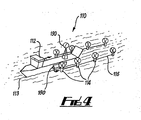
- FIG 4 there is shown a further embodiment of offshore apparatus 110 for capturing energy.
- Many of the features of the apparatus 110 are similar to those of the apparatus 10 described above, and like features are denoted with the same reference numerals incremented by one hundred.
- the ship 112 is shown during deployment of energy capture buoys 114.
- the buoys are initially stored, in a transport configuration, in slots in a hold 180 of the ship. While stored, the ship 112 can travel relatively rapidly to a high energy location where it is desirable to capture energy for generating power. In that location, the array of energy capture buoys 114 is deployed into the sea for operation, such as in the manner described with reference to the above embodiments.
- the ship when it is desired to offload the power, the ship recovers the energy capture buoys, and the power stored by the buoys 114 is transmitted through a solid electrical connections provided in individual storage slots (which receive the buoys) on the ship, and through a connection cable carried on board the ship to a subsea station.
- the ship 112 may then move to another location and re-deploy the array of buoys for energy capture.
- the ship 112 is additionally fitted with a wind turbine 190 and thereby contributes to the production of power together with energy capture buoys.
- the presently described offshore apparatus and method provides significant benefits in efficiency of capture and offloading of power or converted gas.
- the mobility of the arrangement of energy capture devices, its significant lateral extent and the number of interface points provided in the arrangement helps to reduce costs associated with energy extraction and transport to shore. Further, transport into high energy locations and orientation of individual devices assist with capture efficiency and maintaining operation at a high level of productivity.
- the energy capture devices could be connected to the ship or each other via a fibre rope or wire tether.
- the arrangement of energy capture devices is autonomous in that it may move under its own propulsion, and does riot rely on being towed by a ship. In this case, one of the energy capture devices may be propelled to move the arrangement.
Landscapes
- Engineering & Computer Science (AREA)
- Chemical & Material Sciences (AREA)
- Mechanical Engineering (AREA)
- Combustion & Propulsion (AREA)
- General Engineering & Computer Science (AREA)
- Sustainable Energy (AREA)
- Sustainable Development (AREA)
- Life Sciences & Earth Sciences (AREA)
- Power Engineering (AREA)
- Ocean & Marine Engineering (AREA)
- Architecture (AREA)
- Civil Engineering (AREA)
- Structural Engineering (AREA)
- Other Liquid Machine Or Engine Such As Wave Power Use (AREA)
- Wind Motors (AREA)
- Revetment (AREA)
Claims (16)
- Offshore-Vorrichtung (10, 110, 310) zur Gewinnung von Energie, wobei die Vorrichtung eine Anordnung von Energiegewinnungseinrichtungen (14, 114, 314) beinhaltet, die betriebsfähig sind, um Energie zu gewinnen, um ein exportierbares Produkt zu erzeugen, wobei die Anordnung eine Vielzahl von seitlich mit Abstand voneinander angeordneten Anschlusspunkten (17) beinhaltet, wobei jeder Anschlusspunkt (17) angepasst ist, um selektiv mit einer Abladeeinheit (22, 322) zum Bewegen des exportierbaren Produkts aus den Energiegewinnungseinrichtungen (14, 114, 314) weg verbunden zu werden, dadurch gekennzeichnet, dass die Anordnung eine Reihe von Energiegewinnungseinrichtungen (14, 114, 314) beinhaltet, die miteinander verbunden sind, so dass eine erste Energiegewinnungseinrichtung (14, 114, 314) in der Reihe unabhängig von einer zweiten Energiegewinnungseinrichtung (14, 114, 314) in der Reihe in Bezug auf die zweite Energiegewinnungseinrichtung (14, 114, 314) in der Reihe in einer seitlichen Richtung bewegbar ist, so dass die erste Energiegewinnungseinrichtung (14, 114, 314) in eine für die Energiegewinnung günstige Position bewegt wird, und wobei die Reihe von Energiegewinnungseinrichtungen (14, 114, 314) angepasst ist, um von einem Fahrzeug (12, 112) von einer ersten Offshore-Stelle zu einer zweiten Offshore-Stelle gezogen zu werden.
- Offshore-Vorrichtung gemäß Anspruch 1, wobei die erste Energiegewinnungseinrichtung (14, 114, 314) einen Propeller (32) zum Bewegen der ersten Energiegewinnungseinrichtung (14, 114, 314) beinhaltet.
- Offshore-Vorrichtung gemäß Anspruch 1 oder Anspruch 2, wobei jeder der Vielzahl von Anschlusspunkten (17) Teil einer separaten Energiegewinnungseinrichtung (14, 114, 314) bildet.
- Offshore-Vorrichtung gemäß einem der vorhergehenden Ansprüche, wobei die Abladeeinheit (22, 322) eine Meeresbodeninstallation beinhaltet.
- Offshore-Vorrichtung gemäß einem der vorhergehenden Ansprüche, wobei das exportierbare Produkt eines oder mehrere von Folgendem beinhaltet: elektrische Leistung; Gas; Flüssigkeiten; und einen Brennstoff.
- Offshore-Vorrichtung gemäß einem der vorhergehenden Ansprüche, wobei die Anordnung von Energiegewinnungseinrichtungen (14, 114, 314) eine Exportvorrichtung zum Erleichtern des Entfernens des Exportprodukts aus den Energiegewinnungseinrichtungen (14, 114, 314) über die Anschlusspunkte (17) beinhaltet, wobei die Exportvorrichtung eine Exportleitung (24) beinhaltet, die angepasst ist, um an einem Ende mit der Abladeeinheit (22, 322) und an einem zweiten Ende mit einem Anschlusspunkt (17) verbunden zu werden.
- Offshore-Vorrichtung gemäß einem der vorhergehenden Ansprüche, wobei die Anordnung eine erste Energiegewinnungseinrichtung (14, 114, 314) beinhaltet, die angepasst ist, um mit der Abladeeinheit (22, 322) verbunden zu werden, wobei die erste Energiegewinnungseinrichtung (14, 114, 314) mit einer zweiten Energiegewinnungseinrichtung (14, 114, 314) verbunden ist, um zu ermöglichen, dass das exportierbare Produkt unter den Energiegewinnungseinrichtungen (14, 114, 314) weitergeleitet und über die erste Energiegewinnungseinrichtung (14, 114, 314) aus der Anordnung entfernt wird.
- Offshore-Vorrichtung gemäß einem der vorhergehenden Ansprüche, wobei die Vorrichtung Lagermittel (30) zum temporären Lagern des exportierbaren Produkts beinhaltet.
- Offshore-Vorrichtung gemäß einem der vorhergehenden Ansprüche, wobei das Fahrzeug (12, 112) angepasst ist, um die Anordnung von Energiegewinnungseinrichtungen (14, 114, 314) zu stationieren und einzuholen.
- Ein Verfahren zum Gewinnen von Energie offshore, wobei das Verfahren die folgenden Schritte beinhaltet:(a) Platzieren einer mobilen Anordnung von Energiegewinnungseinrichtungen (14, 114, 314) an einer ersten Offshore-Stelle, wobei die Anordnung eine Reihe von Energiegewinnungseinrichtungen (14, 114, 314) beinhaltet, die miteinander verbunden sind, so dass eine erste Energiegewinnungseinrichtung (14, 114, 314) in der Reihe unabhängig von einer zweiten Energiegewinnungseinrichtung (14, 114, 314) in der Reihe in Bezug auf die zweite Energiegewinnungseinrichtung (14, 114, 314) in einer seitlichen Richtung bewegbar ist;(b) Ziehen der Reihe von Energiegewinnungseinrichtungen (14, 114, 314) von der ersten Offshore-Stelle zu einer zweiten Offshore-Stelle;(c) seitliches Steuern und Bewegen einer Energiegewinnungseinrichtung (14, 114, 314) innerhalb der Anordnung in eine günstige Ausrichtung zur Energiegewinnung;(d) Gewinnen von Energie, um ein exportierbares Produkt zu erzeugen, unter Verwendung der Energiegewinnungseinrichtungen (14, 114, 314);(e) Auswählen einer der Vielzahl von Anschlusspunkten (17) auf den Energiegewinnungseinrichtungen (14, 114, 314) zum Verbinden mit einer Abladeeinheit (22, 322); und(f) Verbinden des ausgewählten Anschlusspunktes (17) mit der Abladeeinheit (22, 322), um das exportierbare Produkt aus der Reihe von Energiegewinnungseinrichtungen (14, 114, 314) weg zu bewegen.
- Verfahren gemäß Anspruch 10, wobei das Verfahren den Schritt des Verbindens eines Anschlusspunktes (17) einer ersten Energiegewinnungseinrichtung (14, 114, 314) mit der Abladeeinheit (22, 322) beinhaltet.
- Verfahren gemäß Anspruch 11, wobei das Verfahren die Schritte des Erzeugens eines exportierbaren Produkts unter Verwendung einer zweiten Energiegewinnungseinrichtung (14, 114, 314) und des Bewegens des exportierbaren Produkts aus der ersten Energiegewinnungseinrichtung (14, 114, 314) über den verbundenen Anschlusspunkt der ersten Einrichtung (14, 114, 314) beinhaltet.
- Ein System zur Offshore-Gewinnung und zum Offshore-Export von Energie, wobei das System Folgendes beinhaltet:- eine Offshore-Vorrichtung gemäß einem der Ansprüche 1 bis 9; und- eine Abladeeinheit (22, 322);wobei ein ausgewählter Anschlusspunkt (17) der Anordnung mit der Abladeeinheit (22, 322) verbunden wird, um das erzeugte exportierbare Produkt aus den Energiegewinnungseinrichtungen (14, 114, 314) weg zu bewegen.
- System gemäß Anspruch 13, wobei die Abladeeinheit eines oder mehrere von Folgendem beinhaltet:- eine Meeresbodenstation oder -installation (22, 322);- einen Tanker/ein Transportschiff (12, 112);- eine Transportpipeline (22, 322);- ein elektrisches Weiterleitungskabel (28);- eine Energieweiterleitungsstation (26);- eine schwimmende Boje oder einen Ponton; und- eine Landeinrichtung.
- System gemäß Anspruch 13 oder Anspruch 14, wobei die Abladeeinheit (22, 322) Verbindungsausrüstung beinhaltet, die angepasst ist, um mit einem Anschlusspunkt (17) der Offshore-Vorrichtung verbunden zu werden.
- System gemäß einem der Ansprüche 13 bis 15, wobei die Abladeeinheit einen Teil eines vorinstallierten Meeresbodentransportsystems bildet.
Applications Claiming Priority (2)
| Application Number | Priority Date | Filing Date | Title |
|---|---|---|---|
| GBGB0607507.1A GB0607507D0 (en) | 2006-04-13 | 2006-04-13 | Method and apparatus for energy capture and transmission |
| PCT/GB2007/001356 WO2007122376A1 (en) | 2006-04-13 | 2007-04-12 | Offshore apparatus for capturing energy |
Publications (2)
| Publication Number | Publication Date |
|---|---|
| EP2018477A1 EP2018477A1 (de) | 2009-01-28 |
| EP2018477B1 true EP2018477B1 (de) | 2015-07-01 |
Family
ID=36571830
Family Applications (1)
| Application Number | Title | Priority Date | Filing Date |
|---|---|---|---|
| EP07732399.6A Active EP2018477B1 (de) | 2006-04-13 | 2007-04-12 | Offshore-vorrichtung zur gewinnung von energie |
Country Status (7)
| Country | Link |
|---|---|
| EP (1) | EP2018477B1 (de) |
| DK (1) | DK2018477T3 (de) |
| ES (1) | ES2546940T3 (de) |
| GB (2) | GB0607507D0 (de) |
| NO (1) | NO337111B1 (de) |
| PT (1) | PT2018477E (de) |
| WO (1) | WO2007122376A1 (de) |
Cited By (1)
| Publication number | Priority date | Publication date | Assignee | Title |
|---|---|---|---|---|
| GB2611369A (en) * | 2022-01-28 | 2023-04-05 | Baker Hughes Energy Technology UK Ltd | Wind turbine array |
Families Citing this family (11)
| Publication number | Priority date | Publication date | Assignee | Title |
|---|---|---|---|---|
| CH700217B1 (fr) * | 2006-07-29 | 2010-08-31 | Suisse Electronique Microtech | Plate-forme solaire |
| ES2358756T3 (es) * | 2007-11-27 | 2011-05-13 | Lm Glasfiber A/S | Transporte marítimo de palas de turbinas eólicas. |
| EP2274515B1 (de) * | 2008-02-29 | 2016-03-23 | Single Buoy Moorings Inc. | Offshore-wind- und wellenkraftwerk sowie verfahren dafür |
| CH699791A2 (it) * | 2008-10-24 | 2010-04-30 | Vittorio Perregrini | Dispositivo generatore integrato per la produzione di energia da fonti alternative rinnovabili ad emissioni zero nel rispetto e protezione ambientale. |
| DE102009051215A1 (de) * | 2009-10-29 | 2011-05-12 | Li-Tec Battery Gmbh | Windkraftanlage mit Batterieanordnung |
| KR101826366B1 (ko) | 2009-11-11 | 2018-02-06 | 프라운호퍼 유에스에이, 인크. | 저장된 에너지의 수송을 이용하는 파동 에너지 수확에 대한 시스템 |
| FR2954268B1 (fr) | 2009-12-23 | 2015-03-06 | Inst Francais Du Petrole | Barge comportant un dispositif eolien multi turbines pour la production d'energie et d'eau |
| CN102454553B (zh) * | 2011-12-26 | 2013-10-09 | 中国科学院工程热物理研究所 | 一种漂浮式风电场 |
| WO2014056049A1 (en) | 2012-10-11 | 2014-04-17 | Bilić Josip | Device using multiple renewable energy sources (dumres) |
| GB201614524D0 (en) * | 2016-08-25 | 2016-10-12 | Edwards Douglas | Platform |
| EP3936749B1 (de) * | 2020-07-06 | 2024-04-17 | Siemens Gamesa Renewable Energy A/S | Verfahren zum installieren einer gastransportanordnung |
Family Cites Families (7)
| Publication number | Priority date | Publication date | Assignee | Title |
|---|---|---|---|---|
| US3988592A (en) * | 1974-11-14 | 1976-10-26 | Porter William H | Electrical generating system |
| US4159427A (en) * | 1975-12-23 | 1979-06-26 | Messerschmitt-Boelkow-Blohm Gesellschaft Mit Beschraenkter Haftung | Apparatus for utilizing natural energies |
| US4850190A (en) * | 1988-05-09 | 1989-07-25 | Pitts Thomas H | Submerged ocean current electrical generator and method for hydrogen production |
| DE19714512C2 (de) * | 1997-04-08 | 1999-06-10 | Tassilo Dipl Ing Pflanz | Maritime Kraftwerksanlage mit Herstellungsprozeß zur Gewinnung, Speicherung und zum Verbrauch von regenerativer Energie |
| NL1013559C2 (nl) * | 1999-11-11 | 2001-05-28 | Peter Alexander Josephus Pas | Systeem voor het uit water produceren van waterstof onder gebruikmaking van een waterstroom zoals een golfstroom of getijdenstroom. |
| GB2383204A (en) * | 2001-09-26 | 2003-06-18 | Ultramarine Corp | Offshore wind driven generator |
| GB2383978B (en) * | 2002-01-11 | 2004-09-08 | Dominic Michaelis | Platform provided with renewable energy converter systems |
-
2006
- 2006-04-13 GB GBGB0607507.1A patent/GB0607507D0/en not_active Ceased
-
2007
- 2007-04-12 DK DK07732399.6T patent/DK2018477T3/da active
- 2007-04-12 ES ES07732399.6T patent/ES2546940T3/es active Active
- 2007-04-12 EP EP07732399.6A patent/EP2018477B1/de active Active
- 2007-04-12 PT PT77323996T patent/PT2018477E/pt unknown
- 2007-04-12 WO PCT/GB2007/001356 patent/WO2007122376A1/en not_active Ceased
-
2008
- 2008-11-10 GB GB0820452A patent/GB2451041A/en not_active Withdrawn
- 2008-11-10 NO NO20084721A patent/NO337111B1/no unknown
Cited By (1)
| Publication number | Priority date | Publication date | Assignee | Title |
|---|---|---|---|---|
| GB2611369A (en) * | 2022-01-28 | 2023-04-05 | Baker Hughes Energy Technology UK Ltd | Wind turbine array |
Also Published As
| Publication number | Publication date |
|---|---|
| ES2546940T3 (es) | 2015-09-30 |
| NO20084721L (no) | 2008-11-10 |
| GB0820452D0 (en) | 2008-12-17 |
| WO2007122376A1 (en) | 2007-11-01 |
| DK2018477T3 (da) | 2015-10-05 |
| GB2451041A (en) | 2009-01-14 |
| PT2018477E (pt) | 2015-10-13 |
| NO337111B1 (no) | 2016-01-25 |
| EP2018477A1 (de) | 2009-01-28 |
| GB0607507D0 (en) | 2006-05-24 |
Similar Documents
| Publication | Publication Date | Title |
|---|---|---|
| EP2018477B1 (de) | Offshore-vorrichtung zur gewinnung von energie | |
| US20220307459A1 (en) | Self-propelled buoyant energy converter and method for deploying same | |
| US11788509B2 (en) | Power generating windbags and waterbags | |
| US12215663B2 (en) | Hydrogen production and conveyance system | |
| US20240068445A1 (en) | Power generating windbags and waterbags | |
| EP3212496B1 (de) | Verbindungssystem für array-kabel von lösbaren offshore-energievorrichtungen | |
| US11242840B2 (en) | Ocean water power-generator | |
| JP7142914B2 (ja) | 再生可能なエネルギバージ船 | |
| US7525212B1 (en) | Ocean power harvester | |
| US6918350B1 (en) | Sea-based hydrogen-oxygen generation system | |
| KR20240055032A (ko) | 수소 생성, 수집 및 분배를 위한 디바이스, 시스템, 및 방법 | |
| GB2618416A (en) | Delivering power to offshore vessels | |
| GB2594310A (en) | Apparatus and method | |
| GB2618350A (en) | Delivering power to offshore vessels | |
| NO20220511A1 (en) | Delivering power to offshore vessels | |
| KR20160146175A (ko) | 전력저장장치가 탑재된 부유식 조류 발전장치와 무인 항공 연 | |
| GB2618415A (en) | Delivering power to offshore vessels |
Legal Events
| Date | Code | Title | Description |
|---|---|---|---|
| PUAI | Public reference made under article 153(3) epc to a published international application that has entered the european phase |
Free format text: ORIGINAL CODE: 0009012 |
|
| 17P | Request for examination filed |
Effective date: 20081107 |
|
| AK | Designated contracting states |
Kind code of ref document: A1 Designated state(s): AT BE BG CH CY CZ DE DK EE ES FI FR GB GR HU IE IS IT LI LT LU LV MC MT NL PL PT RO SE SI SK TR |
|
| AX | Request for extension of the european patent |
Extension state: AL BA HR MK RS |
|
| 17Q | First examination report despatched |
Effective date: 20100823 |
|
| DAX | Request for extension of the european patent (deleted) | ||
| GRAP | Despatch of communication of intention to grant a patent |
Free format text: ORIGINAL CODE: EPIDOSNIGR1 |
|
| INTG | Intention to grant announced |
Effective date: 20141017 |
|
| RAP1 | Party data changed (applicant data changed or rights of an application transferred) |
Owner name: WEST OCEAN ENERGY LIMITED |
|
| RIN1 | Information on inventor provided before grant (corrected) |
Inventor name: WEST ALAN |
|
| GRAP | Despatch of communication of intention to grant a patent |
Free format text: ORIGINAL CODE: EPIDOSNIGR1 |
|
| INTG | Intention to grant announced |
Effective date: 20150311 |
|
| GRAS | Grant fee paid |
Free format text: ORIGINAL CODE: EPIDOSNIGR3 |
|
| GRAA | (expected) grant |
Free format text: ORIGINAL CODE: 0009210 |
|
| AK | Designated contracting states |
Kind code of ref document: B1 Designated state(s): AT BE BG CH CY CZ DE DK EE ES FI FR GB GR HU IE IS IT LI LT LU LV MC MT NL PL PT RO SE SI SK TR |
|
| REG | Reference to a national code |
Ref country code: GB Ref legal event code: FG4D |
|
| REG | Reference to a national code |
Ref country code: AT Ref legal event code: REF Ref document number: 734116 Country of ref document: AT Kind code of ref document: T Effective date: 20150715 Ref country code: CH Ref legal event code: EP |
|
| REG | Reference to a national code |
Ref country code: IE Ref legal event code: FG4D |
|
| REG | Reference to a national code |
Ref country code: DE Ref legal event code: R096 Ref document number: 602007041937 Country of ref document: DE |
|
| REG | Reference to a national code |
Ref country code: ES Ref legal event code: FG2A Ref document number: 2546940 Country of ref document: ES Kind code of ref document: T3 Effective date: 20150930 |
|
| REG | Reference to a national code |
Ref country code: DK Ref legal event code: T3 Effective date: 20150930 |
|
| REG | Reference to a national code |
Ref country code: PT Ref legal event code: SC4A Free format text: AVAILABILITY OF NATIONAL TRANSLATION Effective date: 20150907 |
|
| REG | Reference to a national code |
Ref country code: NL Ref legal event code: FP |
|
| REG | Reference to a national code |
Ref country code: AT Ref legal event code: MK05 Ref document number: 734116 Country of ref document: AT Kind code of ref document: T Effective date: 20150701 |
|
| REG | Reference to a national code |
Ref country code: LT Ref legal event code: MG4D |
|
| PG25 | Lapsed in a contracting state [announced via postgrant information from national office to epo] |
Ref country code: LT Free format text: LAPSE BECAUSE OF FAILURE TO SUBMIT A TRANSLATION OF THE DESCRIPTION OR TO PAY THE FEE WITHIN THE PRESCRIBED TIME-LIMIT Effective date: 20150701 Ref country code: FI Free format text: LAPSE BECAUSE OF FAILURE TO SUBMIT A TRANSLATION OF THE DESCRIPTION OR TO PAY THE FEE WITHIN THE PRESCRIBED TIME-LIMIT Effective date: 20150701 Ref country code: GR Free format text: LAPSE BECAUSE OF FAILURE TO SUBMIT A TRANSLATION OF THE DESCRIPTION OR TO PAY THE FEE WITHIN THE PRESCRIBED TIME-LIMIT Effective date: 20151002 Ref country code: LV Free format text: LAPSE BECAUSE OF FAILURE TO SUBMIT A TRANSLATION OF THE DESCRIPTION OR TO PAY THE FEE WITHIN THE PRESCRIBED TIME-LIMIT Effective date: 20150701 |
|
| PG25 | Lapsed in a contracting state [announced via postgrant information from national office to epo] |
Ref country code: AT Free format text: LAPSE BECAUSE OF FAILURE TO SUBMIT A TRANSLATION OF THE DESCRIPTION OR TO PAY THE FEE WITHIN THE PRESCRIBED TIME-LIMIT Effective date: 20150701 Ref country code: SE Free format text: LAPSE BECAUSE OF FAILURE TO SUBMIT A TRANSLATION OF THE DESCRIPTION OR TO PAY THE FEE WITHIN THE PRESCRIBED TIME-LIMIT Effective date: 20150701 Ref country code: PL Free format text: LAPSE BECAUSE OF FAILURE TO SUBMIT A TRANSLATION OF THE DESCRIPTION OR TO PAY THE FEE WITHIN THE PRESCRIBED TIME-LIMIT Effective date: 20150701 |
|
| REG | Reference to a national code |
Ref country code: DE Ref legal event code: R097 Ref document number: 602007041937 Country of ref document: DE Ref country code: FR Ref legal event code: PLFP Year of fee payment: 10 |
|
| PG25 | Lapsed in a contracting state [announced via postgrant information from national office to epo] |
Ref country code: SK Free format text: LAPSE BECAUSE OF FAILURE TO SUBMIT A TRANSLATION OF THE DESCRIPTION OR TO PAY THE FEE WITHIN THE PRESCRIBED TIME-LIMIT Effective date: 20150701 Ref country code: IT Free format text: LAPSE BECAUSE OF FAILURE TO SUBMIT A TRANSLATION OF THE DESCRIPTION OR TO PAY THE FEE WITHIN THE PRESCRIBED TIME-LIMIT Effective date: 20150701 Ref country code: CZ Free format text: LAPSE BECAUSE OF FAILURE TO SUBMIT A TRANSLATION OF THE DESCRIPTION OR TO PAY THE FEE WITHIN THE PRESCRIBED TIME-LIMIT Effective date: 20150701 Ref country code: EE Free format text: LAPSE BECAUSE OF FAILURE TO SUBMIT A TRANSLATION OF THE DESCRIPTION OR TO PAY THE FEE WITHIN THE PRESCRIBED TIME-LIMIT Effective date: 20150701 |
|
| PLBE | No opposition filed within time limit |
Free format text: ORIGINAL CODE: 0009261 |
|
| STAA | Information on the status of an ep patent application or granted ep patent |
Free format text: STATUS: NO OPPOSITION FILED WITHIN TIME LIMIT |
|
| PG25 | Lapsed in a contracting state [announced via postgrant information from national office to epo] |
Ref country code: RO Free format text: LAPSE BECAUSE OF FAILURE TO SUBMIT A TRANSLATION OF THE DESCRIPTION OR TO PAY THE FEE WITHIN THE PRESCRIBED TIME-LIMIT Effective date: 20150701 |
|
| 26N | No opposition filed |
Effective date: 20160404 |
|
| PG25 | Lapsed in a contracting state [announced via postgrant information from national office to epo] |
Ref country code: SI Free format text: LAPSE BECAUSE OF FAILURE TO SUBMIT A TRANSLATION OF THE DESCRIPTION OR TO PAY THE FEE WITHIN THE PRESCRIBED TIME-LIMIT Effective date: 20150701 |
|
| REG | Reference to a national code |
Ref country code: CH Ref legal event code: PL |
|
| PG25 | Lapsed in a contracting state [announced via postgrant information from national office to epo] |
Ref country code: LU Free format text: LAPSE BECAUSE OF FAILURE TO SUBMIT A TRANSLATION OF THE DESCRIPTION OR TO PAY THE FEE WITHIN THE PRESCRIBED TIME-LIMIT Effective date: 20160412 |
|
| PG25 | Lapsed in a contracting state [announced via postgrant information from national office to epo] |
Ref country code: LI Free format text: LAPSE BECAUSE OF NON-PAYMENT OF DUE FEES Effective date: 20160430 Ref country code: CH Free format text: LAPSE BECAUSE OF NON-PAYMENT OF DUE FEES Effective date: 20160430 |
|
| REG | Reference to a national code |
Ref country code: FR Ref legal event code: PLFP Year of fee payment: 11 |
|
| REG | Reference to a national code |
Ref country code: FR Ref legal event code: PLFP Year of fee payment: 12 |
|
| PG25 | Lapsed in a contracting state [announced via postgrant information from national office to epo] |
Ref country code: HU Free format text: LAPSE BECAUSE OF FAILURE TO SUBMIT A TRANSLATION OF THE DESCRIPTION OR TO PAY THE FEE WITHIN THE PRESCRIBED TIME-LIMIT; INVALID AB INITIO Effective date: 20070412 Ref country code: CY Free format text: LAPSE BECAUSE OF FAILURE TO SUBMIT A TRANSLATION OF THE DESCRIPTION OR TO PAY THE FEE WITHIN THE PRESCRIBED TIME-LIMIT Effective date: 20150701 |
|
| PG25 | Lapsed in a contracting state [announced via postgrant information from national office to epo] |
Ref country code: TR Free format text: LAPSE BECAUSE OF FAILURE TO SUBMIT A TRANSLATION OF THE DESCRIPTION OR TO PAY THE FEE WITHIN THE PRESCRIBED TIME-LIMIT Effective date: 20150701 Ref country code: MC Free format text: LAPSE BECAUSE OF FAILURE TO SUBMIT A TRANSLATION OF THE DESCRIPTION OR TO PAY THE FEE WITHIN THE PRESCRIBED TIME-LIMIT Effective date: 20150701 Ref country code: MT Free format text: LAPSE BECAUSE OF NON-PAYMENT OF DUE FEES Effective date: 20160430 |
|
| PG25 | Lapsed in a contracting state [announced via postgrant information from national office to epo] |
Ref country code: BG Free format text: LAPSE BECAUSE OF FAILURE TO SUBMIT A TRANSLATION OF THE DESCRIPTION OR TO PAY THE FEE WITHIN THE PRESCRIBED TIME-LIMIT Effective date: 20150701 |
|
| PG25 | Lapsed in a contracting state [announced via postgrant information from national office to epo] |
Ref country code: PT Free format text: LAPSE BECAUSE OF NON-PAYMENT OF DUE FEES Effective date: 20181012 |
|
| PG25 | Lapsed in a contracting state [announced via postgrant information from national office to epo] |
Ref country code: PT Free format text: LAPSE BECAUSE OF NON-PAYMENT OF DUE FEES Effective date: 20181012 |
|
| PGRI | Patent reinstated in contracting state [announced from national office to epo] |
Ref country code: PT Effective date: 20190227 |
|
| PGFP | Annual fee paid to national office [announced via postgrant information from national office to epo] |
Ref country code: PT Payment date: 20210429 Year of fee payment: 15 |
|
| PGFP | Annual fee paid to national office [announced via postgrant information from national office to epo] |
Ref country code: IS Payment date: 20210429 Year of fee payment: 15 |
|
| PGFP | Annual fee paid to national office [announced via postgrant information from national office to epo] |
Ref country code: NL Payment date: 20211029 Year of fee payment: 15 |
|
| PGFP | Annual fee paid to national office [announced via postgrant information from national office to epo] |
Ref country code: BE Payment date: 20211029 Year of fee payment: 15 |
|
| PGFP | Annual fee paid to national office [announced via postgrant information from national office to epo] |
Ref country code: FR Payment date: 20220502 Year of fee payment: 16 Ref country code: DK Payment date: 20220502 Year of fee payment: 16 Ref country code: DE Payment date: 20220502 Year of fee payment: 16 |
|
| REG | Reference to a national code |
Ref country code: NL Ref legal event code: MM Effective date: 20220501 |
|
| REG | Reference to a national code |
Ref country code: BE Ref legal event code: MM Effective date: 20220430 |
|
| PG25 | Lapsed in a contracting state [announced via postgrant information from national office to epo] |
Ref country code: PT Free format text: LAPSE BECAUSE OF NON-PAYMENT OF DUE FEES Effective date: 20221012 Ref country code: NL Free format text: LAPSE BECAUSE OF NON-PAYMENT OF DUE FEES Effective date: 20220501 |
|
| PGFP | Annual fee paid to national office [announced via postgrant information from national office to epo] |
Ref country code: ES Payment date: 20221109 Year of fee payment: 16 |
|
| PG25 | Lapsed in a contracting state [announced via postgrant information from national office to epo] |
Ref country code: BE Free format text: LAPSE BECAUSE OF NON-PAYMENT OF DUE FEES Effective date: 20220430 |
|
| REG | Reference to a national code |
Ref country code: DE Ref legal event code: R119 Ref document number: 602007041937 Country of ref document: DE |
|
| REG | Reference to a national code |
Ref country code: DK Ref legal event code: EBP Effective date: 20230430 |
|
| PG25 | Lapsed in a contracting state [announced via postgrant information from national office to epo] |
Ref country code: FR Free format text: LAPSE BECAUSE OF NON-PAYMENT OF DUE FEES Effective date: 20230430 Ref country code: DE Free format text: LAPSE BECAUSE OF NON-PAYMENT OF DUE FEES Effective date: 20231103 |
|
| PG25 | Lapsed in a contracting state [announced via postgrant information from national office to epo] |
Ref country code: DK Free format text: LAPSE BECAUSE OF NON-PAYMENT OF DUE FEES Effective date: 20230430 |
|
| REG | Reference to a national code |
Ref country code: ES Ref legal event code: FD2A Effective date: 20240528 |
|
| PG25 | Lapsed in a contracting state [announced via postgrant information from national office to epo] |
Ref country code: ES Free format text: LAPSE BECAUSE OF NON-PAYMENT OF DUE FEES Effective date: 20230413 |
|
| PG25 | Lapsed in a contracting state [announced via postgrant information from national office to epo] |
Ref country code: ES Free format text: LAPSE BECAUSE OF NON-PAYMENT OF DUE FEES Effective date: 20230413 |
|
| PGFP | Annual fee paid to national office [announced via postgrant information from national office to epo] |
Ref country code: GB Payment date: 20250429 Year of fee payment: 19 |
|
| PGFP | Annual fee paid to national office [announced via postgrant information from national office to epo] |
Ref country code: IE Payment date: 20250429 Year of fee payment: 19 |
|
| PG25 | Lapsed in a contracting state [announced via postgrant information from national office to epo] |
Ref country code: IS Free format text: LAPSE BECAUSE OF NON-PAYMENT OF DUE FEES Effective date: 20221104 |