EP2018487B1 - Roulement linéaire - Google Patents
Roulement linéaire Download PDFInfo
- Publication number
- EP2018487B1 EP2018487B1 EP07728756A EP07728756A EP2018487B1 EP 2018487 B1 EP2018487 B1 EP 2018487B1 EP 07728756 A EP07728756 A EP 07728756A EP 07728756 A EP07728756 A EP 07728756A EP 2018487 B1 EP2018487 B1 EP 2018487B1
- Authority
- EP
- European Patent Office
- Prior art keywords
- head piece
- deflection means
- section
- outer deflection
- supporting part
- Prior art date
- Legal status (The legal status is an assumption and is not a legal conclusion. Google has not performed a legal analysis and makes no representation as to the accuracy of the status listed.)
- Ceased
Links
- 239000000463 material Substances 0.000 claims abstract description 39
- 239000004033 plastic Substances 0.000 claims description 29
- 229920003023 plastic Polymers 0.000 claims description 29
- 238000005096 rolling process Methods 0.000 claims description 24
- 238000001746 injection moulding Methods 0.000 claims description 9
- 238000007789 sealing Methods 0.000 description 5
- 238000002347 injection Methods 0.000 description 4
- 239000007924 injection Substances 0.000 description 4
- 229920010502 Hytrel® 5555HS Polymers 0.000 description 3
- 238000013016 damping Methods 0.000 description 3
- 238000004519 manufacturing process Methods 0.000 description 3
- 229910000831 Steel Inorganic materials 0.000 description 2
- 239000003365 glass fiber Substances 0.000 description 2
- 239000000314 lubricant Substances 0.000 description 2
- 229920000728 polyester Polymers 0.000 description 2
- 239000010959 steel Substances 0.000 description 2
- 229920001169 thermoplastic Polymers 0.000 description 2
- 239000004416 thermosoftening plastic Substances 0.000 description 2
- 230000005540 biological transmission Effects 0.000 description 1
- 238000005520 cutting process Methods 0.000 description 1
- 230000000694 effects Effects 0.000 description 1
- 239000013013 elastic material Substances 0.000 description 1
- 230000002349 favourable effect Effects 0.000 description 1
- 239000000835 fiber Substances 0.000 description 1
- 238000009413 insulation Methods 0.000 description 1
- 239000002184 metal Substances 0.000 description 1
- 238000000034 method Methods 0.000 description 1
- 230000002028 premature Effects 0.000 description 1
- 239000012858 resilient material Substances 0.000 description 1
- 239000007779 soft material Substances 0.000 description 1
- 238000005507 spraying Methods 0.000 description 1
- 230000007704 transition Effects 0.000 description 1
Images

Classifications
-
- F—MECHANICAL ENGINEERING; LIGHTING; HEATING; WEAPONS; BLASTING
- F16—ENGINEERING ELEMENTS AND UNITS; GENERAL MEASURES FOR PRODUCING AND MAINTAINING EFFECTIVE FUNCTIONING OF MACHINES OR INSTALLATIONS; THERMAL INSULATION IN GENERAL
- F16C—SHAFTS; FLEXIBLE SHAFTS; ELEMENTS OR CRANKSHAFT MECHANISMS; ROTARY BODIES OTHER THAN GEARING ELEMENTS; BEARINGS
- F16C29/00—Bearings for parts moving only linearly
- F16C29/04—Ball or roller bearings
- F16C29/06—Ball or roller bearings in which the rolling bodies circulate partly without carrying load
- F16C29/0602—Details of the bearing body or carriage or parts thereof, e.g. methods for manufacturing or assembly
- F16C29/0609—Details of the bearing body or carriage or parts thereof, e.g. methods for manufacturing or assembly of the ends of the bearing body or carriage where the rolling elements change direction, e.g. end caps
-
- F—MECHANICAL ENGINEERING; LIGHTING; HEATING; WEAPONS; BLASTING
- F16—ENGINEERING ELEMENTS AND UNITS; GENERAL MEASURES FOR PRODUCING AND MAINTAINING EFFECTIVE FUNCTIONING OF MACHINES OR INSTALLATIONS; THERMAL INSULATION IN GENERAL
- F16C—SHAFTS; FLEXIBLE SHAFTS; ELEMENTS OR CRANKSHAFT MECHANISMS; ROTARY BODIES OTHER THAN GEARING ELEMENTS; BEARINGS
- F16C29/00—Bearings for parts moving only linearly
- F16C29/04—Ball or roller bearings
- F16C29/06—Ball or roller bearings in which the rolling bodies circulate partly without carrying load
- F16C29/0633—Ball or roller bearings in which the rolling bodies circulate partly without carrying load with a bearing body defining a U-shaped carriage, i.e. surrounding a guide rail or track on three sides
- F16C29/0635—Ball or roller bearings in which the rolling bodies circulate partly without carrying load with a bearing body defining a U-shaped carriage, i.e. surrounding a guide rail or track on three sides whereby the return paths are provided as bores in a main body of the U-shaped carriage, e.g. the main body of the U-shaped carriage is a single part with end caps provided at each end
- F16C29/0638—Ball or roller bearings in which the rolling bodies circulate partly without carrying load with a bearing body defining a U-shaped carriage, i.e. surrounding a guide rail or track on three sides whereby the return paths are provided as bores in a main body of the U-shaped carriage, e.g. the main body of the U-shaped carriage is a single part with end caps provided at each end with balls
- F16C29/0642—Ball or roller bearings in which the rolling bodies circulate partly without carrying load with a bearing body defining a U-shaped carriage, i.e. surrounding a guide rail or track on three sides whereby the return paths are provided as bores in a main body of the U-shaped carriage, e.g. the main body of the U-shaped carriage is a single part with end caps provided at each end with balls with four rows of balls
- F16C29/0645—Ball or roller bearings in which the rolling bodies circulate partly without carrying load with a bearing body defining a U-shaped carriage, i.e. surrounding a guide rail or track on three sides whereby the return paths are provided as bores in a main body of the U-shaped carriage, e.g. the main body of the U-shaped carriage is a single part with end caps provided at each end with balls with four rows of balls with load directions in O-arrangement
-
- F—MECHANICAL ENGINEERING; LIGHTING; HEATING; WEAPONS; BLASTING
- F16—ENGINEERING ELEMENTS AND UNITS; GENERAL MEASURES FOR PRODUCING AND MAINTAINING EFFECTIVE FUNCTIONING OF MACHINES OR INSTALLATIONS; THERMAL INSULATION IN GENERAL
- F16C—SHAFTS; FLEXIBLE SHAFTS; ELEMENTS OR CRANKSHAFT MECHANISMS; ROTARY BODIES OTHER THAN GEARING ELEMENTS; BEARINGS
- F16C2202/00—Solid materials defined by their properties
- F16C2202/02—Mechanical properties
- F16C2202/06—Strength or rigidity
-
- F—MECHANICAL ENGINEERING; LIGHTING; HEATING; WEAPONS; BLASTING
- F16—ENGINEERING ELEMENTS AND UNITS; GENERAL MEASURES FOR PRODUCING AND MAINTAINING EFFECTIVE FUNCTIONING OF MACHINES OR INSTALLATIONS; THERMAL INSULATION IN GENERAL
- F16C—SHAFTS; FLEXIBLE SHAFTS; ELEMENTS OR CRANKSHAFT MECHANISMS; ROTARY BODIES OTHER THAN GEARING ELEMENTS; BEARINGS
- F16C2202/00—Solid materials defined by their properties
- F16C2202/02—Mechanical properties
- F16C2202/08—Resilience, elasticity, super-elasticity
Definitions
- the present invention relates to a linear roller bearing, in which a guide carriage can be guided longitudinally displaceably on a guide rail.
- a linear roller bearing has become known in which a guide carriage is arranged longitudinally displaceably on a guide rail.
- the carriage is provided for an endless circulation of rolling elements with several endless WälzSystemkanälen.
- Each rolling element channel comprises a load section, a return section and two deflection sections connecting the load section to the return section.
- the load section the rolling elements roll on tracks of the guide rail and the guide carriage.
- the return section the rolling elements are returned free of load.
- the deflecting sections the rolling elements are deflected from the load section into the return section or vice versa.
- Each deflecting section has an inner deflection provided with an inner deflecting path and an outer deflecting provided with an outer deflecting path.
- the outer deflection is integrally formed on a head piece of the guide carriage made of plastic.
- the inner deflection is formed on a separate piece of plastic, which is like the head piece attached to the front side of a support body of the carriage. Particularly at high speeds of rotation, the rotating rolling elements exert considerable centrifugal forces on the deflection sections.
- the outer deflection may be provided with a lifting ramp on which the rolling elements of the guide rail be lifted off.
- a wear-resistant hard plastic is usually selected, which can be properly attached to the support body.
- the aforementioned lifting ramp is then also formed from this wear-resistant plastic.
- this lifting lamp is at risk of breakage due to its hardness and brittleness. Especially at high speeds of the rolling elements, this risk of breakage.
- a breakage of the lifting ramp or its wear affects the running behavior of the rolling elements in the circulation channel, with the result of premature failure of the linear roller bearing.
- Object of the present invention is to provide a linear roller bearing according to the features of the preamble of claim 1, which is easy to manufacture and in which a perfect deflection of the rolling elements is ensured, especially in the deflection.
- the head piece can be properly attached to the support body. Because the support part of the head piece is then formed of a harder material with the smaller compliance. The carrier part consequently forms a skeleton which gives the headpiece its mechanical stability. Here, a commonly used plastic can be used. In contrast, the outer deflection, in particular with the lifting ramp, is formed according to the invention from the second material with a greater flexibility.
- the outer deflection of the second material have a compliance, the amount of which is greater than 0.15.
- a material is preferably provided, the flexibility of the amount of which is less than 0.15, preferably less than 0.1.
- the inventively proposed material preferably plastic is much softer or softer than the plastic materials previously used for this purpose.
- Run tests under high-speed conditions have shown that due to the comparatively rubber-like material behavior, the materials provided for the outer deflection dampen impacts of the rolling elements occurring, in particular in the deflection region, without significant wear being associated with this damping.
- a possibly reduced tensile strength of the softer material has been found that the wear is significantly reduced, especially in the deflection compared to known carriages.
- the service life of linear roller bearings according to the invention is markedly increased over known linear roller bearings in high-speed applications.
- an upper limit of compliance is determined by the absence of any plastic deformation, particularly external deflection, due to the effective centrifugal forces.
- plastics whose breaking stress is less than 60 Mpa Equally good results have been observed with plastics, whose elongation at break is greater than 10%, preferably greater than 100%.
- plastics whose breaking stress is less than 60 Mpa and whose elongation at break is greater than 100% show excellent properties to absorb the centrifugal forces of the rolling elements in the deflection, without a significant wear on the outer deflection is observed.
- a material can be provided, the flexibility of which is preferably significantly less than 0.15.
- a glass fiber reinforced PA66 can reach values of about 0.07 here.
- These rigid materials are suitable in a favorable manner as a support structure for the soft outer deflection. These support members can be easily attached to the support body of the carriage in a known manner.
- the known multi-component injection technique allows the injection of the head piece according to the invention in a common injection mold with two different plastics, which form the first and the second material.
- a linear roller bearing is formed, which ensures, in particular in high-speed applications that damage to the outer deflection are avoided when the rolling elements are lifted at high rotational speeds of the guide rail and lifted on the lifting ramp of the outer deflection in the deflection.
- the material for the external deflection is chosen so that a sufficient elasticity is ensured with sufficient dimensional stability.
- the outer deflection formed from the resilient or soft material allows cushioning of the rolling element pulse when the rolling elements are lifted at high speeds from the guide rail and displaced into the deflection path into it.
- the cushioning is made possible by the flexing of the elastic material in the deflection.
- the softer material offers the advantage of noise reduction, as well as a reduction of wear in the deflection section.
- the head piece is located with its the mounting body facing mounting side on the front side of the support body.
- the mounting side of the head piece is formed in an advantageous manner on a cover layer also formed from the second material, which is formed on the support part of the head piece.
- This cover layer can also be sprayed properly and without difficulty in multi-component injection molding together with the carrier part.
- This soft cover layer is therefore arranged between the hard component of the supporting support part of the head piece and the support body of the guide carriage. This soft cover layer thus offers the advantage of additional damping of the overall system.
- the system allows a sealing lip of the lifting ramp under bias to the guide rail also that the lubricant from the circulation channel of the rolling elements is no longer discharged from the Wälz Scheme. Optionally, thus consuming double lip seals omitted as additional elements.
- a front scraper may additionally be formed on the head piece in the usual way.
- This front scraper is then also formed from the second material with the greater compliance, which also applies here, that this front scraper can be made in a single operation together with the outer deflection and the support member by injection molding in multi-component injection molding.
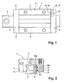
- FIGS. 1 to 4 Pictured linear roller bearing according to the invention has a carriage 1, which is guided on a guide rail 2 longitudinally displaceable.
- the guide carriage 1 comprises a support body 3 and frontally flanged to the support body 3 head pieces 4.
- the roughly U-shaped guide carriage 1 engages with its two legs 5, the guide rail 2 at its two longitudinal sides.
- Each headpiece is provided with corresponding leg portions 6 and a back 7 connecting the two leg portions 6.
- the carriage 1 is provided with four endless circulation channels 8, of which two are superimposed and formed on a leg 5 of the carriage 1.
- each circulation channel 8 formed by balls rolling elements 9 run around endlessly.
- the circulation channel 8 has a load section 10, a return section 11, and two deflection sections 12 connecting the return section 11 to the load section 10.
- the load section 10 and the return section 11 are in the FIG. 2 displayed.
- One of the deflection portions 12 of a leg 5 is shown schematically in the FIG. 1 each deflecting section has an outer deflection 13 and an inner deflection 14, wherein the outer deflection 13 is provided with an outer deflecting path 15 and the inner deflecting 14 is provided with an inner deflecting path 16.
- the head piece 4 is shown in various sections and will be explained in more detail below.
- FIG. 3 shows one of the legs 5 and a part of the cut back 7.
- This head piece 4 according to the invention is formed of plastic, wherein two plastics are used.
- the first plastic is a first material with a smaller compliance and the second plastic is a second material formed with a contrast greater compliance.
- the first plastic is shown in gray shades.
- the second plastic with the greater compliance is shown in Figures 3 to 5 bright (without shading).
- FIG. 3 shows FIG. 3 in that the head piece 4 has a support part 17 which is formed from the first material with the smaller compliance.
- the outer deflector 13 is formed of the second material with the greater compliance.
- the first plastic for the support part by glass fiber reinforced PA66 and the second plastic for external deflection by thermoplastic polyester Hytrel 5555HS is formed.
- the head piece 4 is provided with a cover layer 19 on its mounting side facing the support body 3.
- This cover layer 19 is also made of the second plastic - in the present case Hytrel 5555HS - formed.
- the cover layer 19 and the outer deflector 13 are integrally connected to each other in the present embodiment.
- the cover layer 19 is not integrally connected to the outer deflection 13. Nevertheless, it is also ensured in this case that the head piece can be sprayed in a single operation in a multi-component injection molding process.
- the cover layer 19 is in the FIG. 3 clearly recognizable as an unshaded, bright blanket.
- FIG. 4 shows a further section through the head piece 4.
- an outer deflection 13 is shown cut, which can be seen here that the outer deflection 13 is formed as part of the cover layer 19 on the support member 17.
- a lifting ramp 18 is provided. If the guide carriage is arranged on the guide rail, this lifting lamp 18 is located with a sealing lip 20 under slight bias on the track of the guide rail 2 at.
- This sealing lip 20 advantageously makes it possible that lubricant provided in the circulation channel 8 does not escape or only exits in a reduced manner, since the region of the transition from the raceway of the guide rail into the deflection section 12 is protected.
- This sealing lip 20 is also formed from the second material with the greater compliance and also produced in the common injection molding in multi-component injection molding.
- front scraper 21 which are provided on the side facing away from the support body 3 front side of the head piece 4, and bear against the guide rail 2.
- front wipers 21 are also formed of the second material with the greater compliance. This front scraper 21 can be formed in the manufacture of the head piece 4 in a single operation in the multi-component injection molding process.
- the mounting side of the head piece 4 molded cover layer 19 formed an intermediate layer which is arranged between the usual manner formed of steel support body of the carriage 1 and the support member 17 of the head piece 4. Since this cover layer 19 is formed of the soft plastic (second material with the greater compliance), a damping of the overall system is favored; the transmission of structure-borne noise between the head piece 4 and the support body 3 is significantly reduced by the cover layer 19.
- the head piece was prepared in a single-pass multicomponent spraying method
- alternative head pieces according to the invention can also be produced if the support member and the outer deflection are prepared as separate parts and then connected together.
- the outer deflection of the second material with the greater compliance and the support member are formed from the first material with the smaller compliance.
- the carrier part made of metal, for example steel, and to inject the outer deflection made of plastic onto the carrier part.
Landscapes
- Engineering & Computer Science (AREA)
- General Engineering & Computer Science (AREA)
- Mechanical Engineering (AREA)
- Bearings For Parts Moving Linearly (AREA)
Abstract
Claims (7)
- Palier à roulement linéaire, comprenant un chariot de guidage (1) supporté sur rouleaux et déplaçable sur un rail de guidage (2), qui présente un corps porteur (3) et, au niveau des deux côtés frontaux du corps porteur (3), une pièce de tête respective (4), des corps de roulement circulant sans fin dans au moins un canal périphérique sans fin (8) du chariot de guidage (1), le canal périphérique (8) présentant une section de charge (10) dans laquelle roulent sous contrainte les corps de roulement sur des pistes de roulement (10a, 10b) du rail de guidage (2) et du chariot de guidage (1), et une section de retour (11), dans laquelle les corps de roulement sont ramenés sans contrainte, et deux sections de renvoi (12) reliant sans fin la section de charge et la section de retour, les corps de roulement étant déviés entre un renvoi extérieur (13) et un renvoi intérieur (14) de la section de renvoi (12), et le renvoi extérieur (13) étant prévu au niveau de la pièce de tête (4), caractérisé en ce que la pièce de tête (4) présente une partie porteuse (17), qui est formée d'un premier matériau ayant une plus faible flexibilité et le renvoi extérieur (13) prévu sur la partie porteuse (17) est formé d'un deuxième matériau ayant une plus grande flexibilité, la flexibilité étant indiquée par un quotient déterminé à partir du rapport de l'allongement à la rupture sur la tension de rupture, l'allongement à la rupture étant indiqué en pourcentage et la tension de rupture en mégapascal, la partie porteuse (17) étant prévue sous forme de structure porteuse pour le renvoi extérieur (13).
- Palier à roulement linéaire selon la revendication 1, dans lequel le deuxième matériau prévu pour le renvoi extérieur (13) présente une flexibilité qui est supérieure en valeur absolue à 0,15.
- Palier à roulement linéaire selon la revendication 1, dans lequel le premier matériau prévu pour la partie porteuse (17) présente une flexibilité qui est inférieure à 0,15, de préférence inférieure à 0,1 en valeur absolue.
- Palier à roulement linéaire selon la revendication 1, dans lequel la pièce de tête (4) est fabriquée en plastique par un procédé de pulvérisation à plusieurs composants, l'un des composants étant constitué par le premier matériau pour la partie porteuse (17) et l'autre composant étant constitué par le deuxième matériau pour le renvoi extérieur (13).
- Palier à roulement linéaire selon la revendication 1, dans lequel la pièce de tête (4) s'applique avec son côté de montage tourné vers le corps porteur (3) contre le côté frontal du corps porteur (3), le côté de montage de la pièce de tête (4) étant formé au niveau d'une couche extérieure (19) constituée du deuxième matériau, laquelle est réalisée sur la partie porteuse (17) de la pièce de tête (4).
- Palier à roulement linéaire selon la revendication 1, dans lequel le renvoi extérieur (13) présente une rampe de levage (18) qui s'étend jusqu'à la bande de roulement (10) du rail de guidage (2).
- Palier à roulement linéaire selon la revendication 6, dans lequel le renvoi extérieur (13) est prévu sur une couche extérieure (19) constituée du deuxième matériau, laquelle est fixée sur la partie porteuse (17).
Applications Claiming Priority (2)
| Application Number | Priority Date | Filing Date | Title |
|---|---|---|---|
| DE102006021932A DE102006021932A1 (de) | 2006-05-11 | 2006-05-11 | Linearwälzlager |
| PCT/EP2007/054303 WO2007131890A1 (fr) | 2006-05-11 | 2007-05-03 | Roulement linéaire |
Publications (2)
| Publication Number | Publication Date |
|---|---|
| EP2018487A1 EP2018487A1 (fr) | 2009-01-28 |
| EP2018487B1 true EP2018487B1 (fr) | 2012-06-27 |
Family
ID=38566901
Family Applications (1)
| Application Number | Title | Priority Date | Filing Date |
|---|---|---|---|
| EP07728756A Ceased EP2018487B1 (fr) | 2006-05-11 | 2007-05-03 | Roulement linéaire |
Country Status (4)
| Country | Link |
|---|---|
| EP (1) | EP2018487B1 (fr) |
| CN (1) | CN101443566A (fr) |
| DE (1) | DE102006021932A1 (fr) |
| WO (1) | WO2007131890A1 (fr) |
Families Citing this family (1)
| Publication number | Priority date | Publication date | Assignee | Title |
|---|---|---|---|---|
| DE102013221472A1 (de) | 2013-10-23 | 2015-04-23 | Schaeffler Technologies AG & Co. KG | Kopfstück für einen an einer Führungsschiene wälzgelagert geführten Wagen |
Family Cites Families (10)
| Publication number | Priority date | Publication date | Assignee | Title |
|---|---|---|---|---|
| JPH0796893B2 (ja) * | 1987-03-12 | 1995-10-18 | 日本トムソン株式会社 | クロスローラ方式の無限直線運動用ころ軸受 |
| JP2604229Y2 (ja) * | 1992-10-14 | 2000-04-24 | 日本トムソン株式会社 | 転がり案内ユニット |
| DE4331014C2 (de) * | 1993-08-12 | 1997-09-04 | Schaeffler Waelzlager Kg | Linearwälzlagerelement |
| JP3544407B2 (ja) * | 1995-05-02 | 2004-07-21 | Thk株式会社 | 転がり案内装置 |
| JP2000161354A (ja) * | 1998-11-25 | 2000-06-13 | Nsk Ltd | リニアガイド装置 |
| DE10342841B4 (de) * | 2003-09-17 | 2010-02-25 | Tollo Linear Ab | Wälzkörperführung |
| US20050123223A1 (en) * | 2003-12-04 | 2005-06-09 | Chi-Meng Liao | Linear guide way with assembling end-cup and the method of fabricating |
| DE10356854B4 (de) * | 2003-12-05 | 2011-06-01 | Hiwin Technologies Corp. | Linearführung mit einer zusammensetzbaren Verschlusseinrichtung und Verfahren zur Einführung von Wälzkugeln |
| DE102005013320B9 (de) * | 2005-03-22 | 2013-04-11 | Hiwin Technologies Corp. | Schmiervorrichtung für eine lineare Gleitführung |
| US7891876B2 (en) * | 2005-11-15 | 2011-02-22 | Schaeffler Kg | Linear roller bearing |
-
2006
- 2006-05-11 DE DE102006021932A patent/DE102006021932A1/de not_active Withdrawn
-
2007
- 2007-05-03 WO PCT/EP2007/054303 patent/WO2007131890A1/fr not_active Ceased
- 2007-05-03 EP EP07728756A patent/EP2018487B1/fr not_active Ceased
- 2007-05-03 CN CNA2007800170142A patent/CN101443566A/zh active Pending
Also Published As
| Publication number | Publication date |
|---|---|
| EP2018487A1 (fr) | 2009-01-28 |
| CN101443566A (zh) | 2009-05-27 |
| WO2007131890A1 (fr) | 2007-11-22 |
| DE102006021932A1 (de) | 2007-11-15 |
Similar Documents
| Publication | Publication Date | Title |
|---|---|---|
| DE102008053932A1 (de) | Linearwälzlager | |
| EP3724526B1 (fr) | Rail télescopique | |
| EP1022477A1 (fr) | Guidage linéaire à éléments roulants | |
| EP2336423B1 (fr) | Elément d'amortissement pour la construction de voies ferrées ayant une couche de glissement, système de rails pour voie ferrée doté d'un élément d'amortissement et procédé de fabrication d'un élément d'amortissement | |
| DE19643737A1 (de) | Linearwälzlager | |
| DE69407011T2 (de) | Verfahren zur Herstellung einer Dichtung für Wälzlager, Dichtung für Wälzlager und mit einer solchen Dichtung versehenes Wälzlager | |
| EP1619401B1 (fr) | Unité de guidage linéaire | |
| DE202005014127U1 (de) | Schubkastenauszugsführung | |
| EP1825156B1 (fr) | Palier a roulement pour deplacements lineaires | |
| EP2018487B1 (fr) | Roulement linéaire | |
| DE10248236A1 (de) | Linearführungseinheit | |
| EP2183493A1 (fr) | Systeme de guidage lineaire | |
| DE2631808C2 (de) | Kugelbüchse für Längsführungen | |
| DE9400440U1 (de) | Linearbewegungsbahnen mit Wälzelementen für verschiebbare oder gleichartige Kupplungen | |
| DE19961571B4 (de) | Innenhülse eines Lagers für begrenzte Längsbewegung | |
| EP1952037B1 (fr) | Palier a roulement lineaire | |
| EP1954954B1 (fr) | Palier a roulement lineaire | |
| EP1387098B1 (fr) | Palier à roulement linéaire | |
| EP1124067A2 (fr) | Palier linéaire à billes | |
| DE102008060759A1 (de) | Führungsschiene einer Laufrollenführung | |
| DE19708370A1 (de) | Kugellager für Längsbewegungen zwischen einer Welle und einem Gehäuse | |
| DE10207596B4 (de) | Wälzlager | |
| DE202017100040U1 (de) | Wälzkörperkäfig für eine Teleskopschiene oder eine Linearführung | |
| DE20006286U1 (de) | Laufrolle aus Kunststoff | |
| DE4311294A1 (de) | Käfig für ein Radial-Wälzlager |
Legal Events
| Date | Code | Title | Description |
|---|---|---|---|
| PUAI | Public reference made under article 153(3) epc to a published international application that has entered the european phase |
Free format text: ORIGINAL CODE: 0009012 |
|
| 17P | Request for examination filed |
Effective date: 20081211 |
|
| AK | Designated contracting states |
Kind code of ref document: A1 Designated state(s): AT BE BG CH CY CZ DE DK EE ES FI FR GB GR HU IE IS IT LI LT LU LV MC MT NL PL PT RO SE SI SK TR |
|
| AX | Request for extension of the european patent |
Extension state: AL BA HR MK RS |
|
| DAX | Request for extension of the european patent (deleted) | ||
| RBV | Designated contracting states (corrected) |
Designated state(s): CH DE FR GB LI |
|
| 17Q | First examination report despatched |
Effective date: 20091016 |
|
| GRAP | Despatch of communication of intention to grant a patent |
Free format text: ORIGINAL CODE: EPIDOSNIGR1 |
|
| RAP1 | Party data changed (applicant data changed or rights of an application transferred) |
Owner name: SCHAEFFLER TECHNOLOGIES AG & CO. KG |
|
| GRAS | Grant fee paid |
Free format text: ORIGINAL CODE: EPIDOSNIGR3 |
|
| GRAA | (expected) grant |
Free format text: ORIGINAL CODE: 0009210 |
|
| AK | Designated contracting states |
Kind code of ref document: B1 Designated state(s): CH DE FR GB LI |
|
| REG | Reference to a national code |
Ref country code: GB Ref legal event code: FG4D Free format text: NOT ENGLISH |
|
| REG | Reference to a national code |
Ref country code: CH Ref legal event code: EP |
|
| REG | Reference to a national code |
Ref country code: DE Ref legal event code: R096 Ref document number: 502007010119 Country of ref document: DE Effective date: 20120823 |
|
| PLBE | No opposition filed within time limit |
Free format text: ORIGINAL CODE: 0009261 |
|
| STAA | Information on the status of an ep patent application or granted ep patent |
Free format text: STATUS: NO OPPOSITION FILED WITHIN TIME LIMIT |
|
| 26N | No opposition filed |
Effective date: 20130328 |
|
| REG | Reference to a national code |
Ref country code: DE Ref legal event code: R097 Ref document number: 502007010119 Country of ref document: DE Effective date: 20130328 |
|
| REG | Reference to a national code |
Ref country code: DE Ref legal event code: R081 Ref document number: 502007010119 Country of ref document: DE Owner name: SCHAEFFLER TECHNOLOGIES AG & CO. KG, DE Free format text: FORMER OWNER: SCHAEFFLER TECHNOLOGIES AG & CO. KG, 91074 HERZOGENAURACH, DE Effective date: 20140213 Ref country code: DE Ref legal event code: R081 Ref document number: 502007010119 Country of ref document: DE Owner name: SCHAEFFLER TECHNOLOGIES GMBH & CO. KG, DE Free format text: FORMER OWNER: SCHAEFFLER TECHNOLOGIES AG & CO. KG, 91074 HERZOGENAURACH, DE Effective date: 20140213 |
|
| REG | Reference to a national code |
Ref country code: CH Ref legal event code: PFUS Owner name: SCHAEFFLER TECHNOLOGIES GMBH AND CO. KG, DE Free format text: FORMER OWNER: SCHAEFFLER TECHNOLOGIES AG AND CO. KG, DE |
|
| REG | Reference to a national code |
Ref country code: CH Ref legal event code: PFA Owner name: SCHAEFFLER TECHNOLOGIES AG AND CO. KG, DE Free format text: FORMER OWNER: SCHAEFFLER TECHNOLOGIES GMBH AND CO. KG, DE |
|
| REG | Reference to a national code |
Ref country code: DE Ref legal event code: R081 Ref document number: 502007010119 Country of ref document: DE Owner name: SCHAEFFLER TECHNOLOGIES AG & CO. KG, DE Free format text: FORMER OWNER: SCHAEFFLER TECHNOLOGIES GMBH & CO. KG, 91074 HERZOGENAURACH, DE Effective date: 20150223 |
|
| REG | Reference to a national code |
Ref country code: FR Ref legal event code: PLFP Year of fee payment: 10 |
|
| REG | Reference to a national code |
Ref country code: FR Ref legal event code: PLFP Year of fee payment: 11 |
|
| REG | Reference to a national code |
Ref country code: FR Ref legal event code: PLFP Year of fee payment: 12 |
|
| PGFP | Annual fee paid to national office [announced via postgrant information from national office to epo] |
Ref country code: CH Payment date: 20180525 Year of fee payment: 12 |
|
| PGFP | Annual fee paid to national office [announced via postgrant information from national office to epo] |
Ref country code: FR Payment date: 20180529 Year of fee payment: 12 |
|
| PGFP | Annual fee paid to national office [announced via postgrant information from national office to epo] |
Ref country code: GB Payment date: 20180530 Year of fee payment: 12 Ref country code: DE Payment date: 20180731 Year of fee payment: 12 |
|
| REG | Reference to a national code |
Ref country code: DE Ref legal event code: R119 Ref document number: 502007010119 Country of ref document: DE |
|
| REG | Reference to a national code |
Ref country code: CH Ref legal event code: PL |
|
| GBPC | Gb: european patent ceased through non-payment of renewal fee |
Effective date: 20190503 |
|
| PG25 | Lapsed in a contracting state [announced via postgrant information from national office to epo] |
Ref country code: CH Free format text: LAPSE BECAUSE OF NON-PAYMENT OF DUE FEES Effective date: 20190531 Ref country code: LI Free format text: LAPSE BECAUSE OF NON-PAYMENT OF DUE FEES Effective date: 20190531 |
|
| PG25 | Lapsed in a contracting state [announced via postgrant information from national office to epo] |
Ref country code: GB Free format text: LAPSE BECAUSE OF NON-PAYMENT OF DUE FEES Effective date: 20190503 Ref country code: DE Free format text: LAPSE BECAUSE OF NON-PAYMENT OF DUE FEES Effective date: 20191203 |
|
| PG25 | Lapsed in a contracting state [announced via postgrant information from national office to epo] |
Ref country code: FR Free format text: LAPSE BECAUSE OF NON-PAYMENT OF DUE FEES Effective date: 20190531 |
|
| P01 | Opt-out of the competence of the unified patent court (upc) registered |
Effective date: 20230522 |