EP2018538B1 - Dispositif d'essai permettant l'analyse tribologique de matériaux - Google Patents
Dispositif d'essai permettant l'analyse tribologique de matériaux Download PDFInfo
- Publication number
- EP2018538B1 EP2018538B1 EP07725087.6A EP07725087A EP2018538B1 EP 2018538 B1 EP2018538 B1 EP 2018538B1 EP 07725087 A EP07725087 A EP 07725087A EP 2018538 B1 EP2018538 B1 EP 2018538B1
- Authority
- EP
- European Patent Office
- Prior art keywords
- test
- force
- drive unit
- test device
- microprocessor
- Prior art date
- Legal status (The legal status is an assumption and is not a legal conclusion. Google has not performed a legal analysis and makes no representation as to the accuracy of the status listed.)
- Active
Links
- 0 CCC*1C=CCC1 Chemical compound CCC*1C=CCC1 0.000 description 1
Images


Classifications
-
- G—PHYSICS
- G01—MEASURING; TESTING
- G01N—INVESTIGATING OR ANALYSING MATERIALS BY DETERMINING THEIR CHEMICAL OR PHYSICAL PROPERTIES
- G01N19/00—Investigating materials by mechanical methods
- G01N19/02—Measuring coefficient of friction between materials
-
- G—PHYSICS
- G01—MEASURING; TESTING
- G01N—INVESTIGATING OR ANALYSING MATERIALS BY DETERMINING THEIR CHEMICAL OR PHYSICAL PROPERTIES
- G01N2203/00—Investigating strength properties of solid materials by application of mechanical stress
- G01N2203/0014—Type of force applied
- G01N2203/0025—Shearing
Definitions
- the present invention relates to a testing device for carrying out tribological investigations of materials. Both the friction conditions of friction partners or the properties of a lubricant, which is introduced between two friction partners, can be examined. In this case, a force is applied to the friction partners to be examined and determines the, resulting from a relative movement friction force.
- friction occurs when the surfaces of two bodies are moved relative to one another under normal force action.
- the absolute magnitude of the frictional force depends on the one hand on the applied normal force and on the other hand on the surface properties and optionally on the properties of a lubricant located between the friction surfaces.
- the friction coefficient ⁇ or the friction coefficient z which indicates the ratio of normal force to the resulting friction force, is also dependent on these variables.
- test devices For tribological measurements, that is to say for investigating the friction between materials, test devices are usually used in which a first test body is moved under a predetermined normal force load relative to at least one second test body.
- the first test body is connected to a corresponding movement device which executes, for example, an oscillating or a rotating movement.
- the second specimen is mounted so that the force required to hold the second specimen during movement is detected.
- a device for the investigation of friction conditions which supports a test body on an elastic support member made of glass, which has a plurality of spring arrangements with different spring stiffness.
- the device is primarily used to determine small friction values with high accuracy. For larger friction values and higher applied forces, this device is less suitable.
- EP 1 607 733 It is proposed to apply the test force to a spherical test specimen, which is guided within a tube, pneumatically or hydraulically. The force between the ball and the second specimen is determined by the supply pressure of the fluid.
- the WO 2006/055 994 A relates to a method for investigating material properties of at least one of two mutually moved samples to which a normal force is applied.
- An increased measurement accuracy is to be achieved in that the normal force is applied contactlessly via at least one magnetic field or at least one gas or fluid flow to a sample body, its holder or a sample guide.
- the US 2002/0062678 A1 describes a testing device for investigating the frictional behavior of materials, comprising a drive unit for translational movement of a first test specimen, a measuring device for measuring the forces which are parallel to the direction of the oscillating force introduction and for detecting the test forces which exist between the first test specimen and a second test specimen act, wherein a load control device is provided, which regulates the acting between the two test specimens test force, and wherein Verspann coupleden are provided which transmit the test movement directly from the drive unit to the test arrangement, and wherein the test device is associated with a computing device, which is controlled by a program is stored in a memory.
- the DE 101 13 591 C1 describes a test device for investigating the sealing, friction and wear behavior of sealing systems with a driven shaft and a holding device for the sealing system, wherein the shaft is mounted without contact via magnetic bearings.
- the present invention has as its object to provide a testing device for tribological examinations available whose structure makes it possible to impress the test force between the friction partners to be examined so that the formation of disturbing vibrations avoided and thus a precise determination of the coefficients of friction is supported.
- the test device By the test device according to the invention, the application of a high-precision, non-vibrational force and thus an exact measurement of friction is made possible.
- the vibration-prone in known tribometers Storage of the specimen assembly decoupled.
- a test piece is connected via the machine bed to the base body to which the other test piece is fastened, without thereby providing degrees of freedom of the transmission elements perpendicular to the direction of the force flow. In this way, the two test specimens on their bearings and the machine bed form a vibratory system.
- vibration-optimized tribometer therefore a decoupled design principle is provided.
- the test device provides for the guidance and storage of the drive unit in the region of the test piece attachment to be stored mechanically decoupled from the machine bed.
- hydrodynamic, hydrostatic, aerodynamic, aerostatic or magnetic bearing types can be used.
- Magnetic bearings can be embodied both at least partially permanently magnetically or else electromagnetically or from a combination of both. It is also possible to combine different decoupled types of bearings or even, while ensuring the required degrees of freedom for the transmission of power, the strigismean angel in conjunction with other known types of bearings such as sliding or rolling bearings.
- a shielding of the magnetic effect is preferably provided in order to avoid a possible influence on the tribological friction point.
- the test device provides to initiate the test load directly by means of decoupled storage, whereby, depending on the bearing design, a largely directed introduction of force is made possible. This results in extended possibilities for test setups, such as for simplified friction measurement on existing components with complex geometries.
- the direction and magnitude of the force that must be applied by the decoupled storage depends on the intended test setup, the required test load and the resulting drive unit weight, which must also be absorbed by the storage.
- the decoupled construction principle according to the invention provides for the elimination of a precise test force and to avoid the transmission of vibrations from the machine bed to the test arrangement an elimination of the forces that are not part of the applied test movement before. This requires an interruption of the closed power flow of these forces between the at least two specimens.
- bracing devices are used, which on the one hand enable adjustment of the range of movement of at least one test specimen in the direction of educakraft introduction while compensating movements, but on the other hand, the test movement, which takes place substantially in a vertical plane for introducing the educakraft, directly from the drive to the test arrangement transfer.
- the drive unit For operation of the drive unit, to which at least one first test body is mounted, and which is decoupled in the region of the für MikroSystembefest Trent with respect to possible lateral forces of the test force, in the case of an oscillating applied movement, for example, a linear motor, a quartz motor, a rotary motor with eccentric or a Serve shakers.
- an oscillating applied movement for example, a linear motor, a quartz motor, a rotary motor with eccentric or a Serve shakers.
- a rotational movement for example, electric motors, quartz motors or planar motors are suitable.
- it is possible to use for operation of a drive unit further suitable drive systems or combinations of different drive systems.
- At least one first test specimen is fixed to the drive unit by means of a fastening device.
- this at least one test specimen are possible: geometric basic body, such as cylinders, cuboids, elements with spherical surfaces or machine components with different geometries.
- the drive unit preferably has a different number of bearing points with regard to the machine bed. These bearings can be designed according to the requirements of the test setup and the position of bracing by decoupled bearings or by bearings with one or more degrees of freedom.
- the overall storage concept must preferably ensure a statically determined storage of the drive unit, which however, as described above, precludes a transmission of disturbing vibrations from the machine bed to the test arrangement.
- several bearing points are provided in the test device according to the invention, which can be arranged for example in a row, in a plane or in space.
- At least one second specimen is fixed or movable with respect to the machine bed.
- this at least one second test body is preferably fixed by means of a fastening device on a base body.
- geometric body such as cylinder or cuboid, which z.
- a point-area, line-area, or area-area contact enable.
- specific forms of contact can be examined for existing machine components.
- the base body, to which the at least one second test specimen is attached is driven.
- a drive unit here come in addition to other suitable drive systems linear motors, quartz motors, rotary motors with or without eccentric, planar motors, shakers or combinations of these drive systems in question.
- compensating elements are preferably provided on the base body, to which the at least one second test body is fixed by means of a fastening device, which ensure an absolute parallelism of the test body surfaces.
- these compensating elements or additional devices are also used to compensate for differences in height, as they occur for example by signs of wear.
- compensating elements spring plates or similar aids can be used in a known manner.
- the test device preferably further comprises a measuring device, which is provided for detecting the required measured values.
- Fundamental is the measurement of the resulting frictional forces, which act, for example, in an oscillating movement between the specimens substantially parallel to the direction of force application of the drive unit, or in a rotating movement in the circumferential direction of the rotating specimen.
- at least one force sensor whose function can be represented, for example, piezoelectronically, by means of strain gauges or by a suitable further measuring principle, serves to measure the frictional force on the preferably stationary test body.
- the resulting frictional force is also detected at the preferably fixed test body by means of at least one force sensor in the circumferential direction of the rotation.
- the movement represents a mixed form of rotating and translatory movement
- the mentioned types of force sensors can also be used to measure rotational forces or forces with translatory and rotational components.
- the measuring device also serves to determine the test force which is applied between the friction surfaces.
- a force sensor for measuring the normal force is preferably arranged on a fastening device of a test specimen.
- the first and the second fastening device are suitable for this purpose.
- the direction and movement of the force and the accessibility of the arrangement of the force sensors is determined.
- sensors whose function can be represented, for example, piezoelectronically, by means of strain gauges (DMS) or by a suitable further measuring principle are suitable for force measurement.
- test force does not act in the direction of the normal force due to the geometric configuration of the test specimens or the test arrangement (eg four-ball arrangement)
- the test force can be measured, for example, by means of a sensor which is arranged with respect to the direction of the force.
- the test force resulting from the normal force can preferably be calculated in the computing device associated with the test device.
- the position of the stored sections is preferably also detected by the measuring device and further processed in the machine control and in particular the load control device.
- the measuring device therefore preferably comprises, in number and arrangement, the position of the decoupled bearing corresponding position sensors, which detect the position of the drive unit with sufficient accuracy.
- sensors detect the position of the drive unit, for example by means of an inductive, capacitive or optical operating principle.
- position sensors which work by means of further suitable measuring principles can also be used.
- the cross section of the section of the drive unit which is guided in the decoupled bearing for example, circular, preferably two sensors by 180 °, three sensors by 120 ° or four sensors offset by 90 ° may be arranged around the drive unit section.
- Such a type of arrangement is preferably appropriate if as many storage functional units, such as magnetic bearings, for example, electromagnets are arranged in the same way.
- a multiplicity of further process parameters are also detected by means of the measuring device.
- process parameters include, for example, the operating data of the drives of the test device or the positioning and position of the test bodies to each other.
- there is also an additional measurement of resultant forces for example in the tensioning devices, and detection of vibrations and other disturbances possibly introduced into the machine bed or drive device.
- the measuring device according to the invention comprises a plurality of sensors which detect the parameters of the test environment. Mainly the temperature, the humidity and the air pressure are to be mentioned as the characteristic values, which influence the test result. However, it may still be necessary to record further characteristic values by means of additional sensors assigned to the measuring device.
- the computing device includes at least one microprocessor controlled by a program stored in memory associated with the microprocessor. This memory can be divided into any number, even different memory areas. From the read-in data of the measuring device, the microprocessor derives the control signals for carrying out the tribological examination. In this case, the load control device as the functional unit of the microprocessor controls the test force, which is applied via the decoupled mounting of the drive unit between the test surfaces.
- All data of the measuring device ie the measured values of all sensors provided on the testing device, are preferably read into this microprocessor.
- the measured values of the force sensors which detect the force between the test specimens and / or the position values of the sections of the drive device in the decoupled bearings, serve as input variables of the Load control device.
- the load control device preferably regulates the normal force acting on the test specimens exactly to the predetermined value.
- the microprocessor preferably comprises electrical interfaces, to which an evaluation device, such as a personal computer (PC) or a device-specific operating unit, which has an input unit such as a keyboard and a display, can be connected.
- an evaluation device such as a personal computer (PC) or a device-specific operating unit, which has an input unit such as a keyboard and a display
- the connection can be made for example by means of a cable or wirelessly preferably by means of wireless LAN, infrared interface or Blue-Tooth technology.
- any suitable software which is present for example on a PC, a device-specific control unit or other evaluation device, further processed.
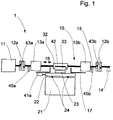
- Fig. 1 shows the schematic structure of a test device 1 according to the invention, in which a first test piece, which is attached to a drive unit, applying a frictional force to a second test piece under an oscillating motion.
- the drive unit 10 includes the drive shaft 15, which extends from the oscillation drive 11 shown on the left to the storage 14 of the drive unit shown on the right.
- the first attachment means 32 for the first Test specimen 33 fixed to the drive shaft 15.
- On both sides of this first fastening device 32 are located on the circumference of the drive shaft 15 each decoupled bearings 13a and 13b, which are designed in the embodiment in the form of magnetic bearings.
- a shield 17 is arranged between the tribological friction point and the magnetic bearings 13, which prevents a magnetic effect on the friction examination.
- bracing devices 12a and 12b are arranged on both sides of the bearings between the bearing 13a and the oscillation drive 11 and between the bearing 13b and bearing 14 of the drive unit. These bracing devices allow adjustment of the vertical degree of freedom of the drive unit with respect to the machine bed.
- a force sensor 42 At the first fastening device 32 is a force sensor 42, which detects the impressed between the two test specimens 23 and 33 normal force.
- the main body 21 is on the machine bed, which in Fig. 1 not shown, arranged.
- the main body 21 is associated with a second fastening means 22, on which the second specimen 23 is fixed.
- the basic body 21 shown here with the second fastening device 22 represents a static carrier unit without drive.
- Compensating elements 24 are arranged between the main body 21 and the second fastening device 22, which ensure the parallelism of the surfaces of the test specimens and compensate, for example, for height differences that arise during wear.
- the second fastening device 22 is associated with a force sensor 41a for detecting the frictional force resulting from the translatory movement of the oscillation drive 11.
- the position of the second specimen 23 is received via the position sensors 45a and 45b associated with the decoupled bearing and via the position sensors 43a and 43b disposed on the two clamps 12a and 12b.
- Fig. 2 the schematic structure of a further test arrangement for a tribological examination is shown.
- the second fastening device 22 is arranged on the base body 21, which is associated with a rotary drive 31, the second fastening device 22 is arranged.
- a disc-shaped second test body 23 is fixed to the illustrated fastening device 22.
- a cylindrical specimen 33 is fixed at the first Fastening device 32.
- the illustrated arrangement is known as a pin-and-space arrangement.
- the drive shaft 15, which is not driven in this embodiment, but impresses the applied by means of decoupled storage test load is in Fig. 2 Not shown.
- the measuring device of in Fig. 2 The test setup shown comprises a rotational force sensor 41b, which is arranged to detect the rotational frictional force on the first fastening device 32. To measure the normal force, which is impressed between the two test specimens, the force sensor 42 is arranged on the first fastening device 32.
- Fig. 3 shows a schematic block diagram of an exemplary computing device 50 of the test device according to the invention.
- Fig. 4 a schematic block diagram of an exemplary control circuit 60 of a load control device is shown.
- the aim of the load control device is to apply to the drive shaft 15 and thus between the two test specimens 23 and 33 in the direction and height predetermined test force.
- the control is responsible for holding the drive shaft 15 in an intended, load-bearing position perpendicular to the test surface. In this case, the sum of all forces acting on the first test body 33 in the intended direction must correspond to the amount of required test force.
- the position of the shaft section 64 is detected via the position sensors 45.
- the amount of force applied by the bearing is received by the force sensor 42.
- the controller 61 controls the current in the electromagnet 63 via the power amplifier 62 so that the desired test force is set.
- the active control achieves a stable levitation state.
Landscapes
- Engineering & Computer Science (AREA)
- Automation & Control Theory (AREA)
- Physics & Mathematics (AREA)
- Health & Medical Sciences (AREA)
- Life Sciences & Earth Sciences (AREA)
- Chemical & Material Sciences (AREA)
- Analytical Chemistry (AREA)
- Biochemistry (AREA)
- General Health & Medical Sciences (AREA)
- General Physics & Mathematics (AREA)
- Immunology (AREA)
- Pathology (AREA)
- Testing Of Devices, Machine Parts, Or Other Structures Thereof (AREA)
Claims (14)
- Dispositif d'essai (1) servant à l'analyse tribologique de matériaux, lequel présente :au moins une première éprouvette (33), qui présente une première surface d'essai,une unité d'entraînement (10) pouvant être entraînée en oscillation et en rotation, servant à déplacer par translation et par rotation l'au moins une première éprouvette (33),un dispositif de mesure (40) servantd'une part à mesurer les forces, qui agissent sensiblement de manière parallèle à la direction d'une application de force par oscillation et dans la direction périphérique d'une application de force par rotation de l'unité d'entraînement (10) d'au moins une deuxième éprouvette (23) ;d'autre part à détecter les forces d'essai, qui agissent entre l'au moins une première éprouvette (33) et l'au moins une deuxième éprouvette (23),en outre un dispositif de réglage de charges, qui règle la force d'essai agissant entre les deux éprouvettes (33, 23),dans lequel la force d'essai spécifiée est appliquée sur les éprouvettes (33, 23) à l'aide d'un support (13) désaccouplé de l'unité d'entraînement (10),dans lequel le principe d'action du support (13) désaccouplé est choisi parmi un groupe, qui comprend des effets magnétiques, hydrostatiques, hydrodynamiques, aérostatiques et aérodynamiques, etdans lequel sont prévus des dispositifs de mise sous tension (12), lesquels transmettent le mouvement d'essai directement depuis l'unité d'entraînement (10) sur l'ensemble d'essai et permettent dans ce cadre des mouvements de compensation en direction de l'application de force d'essai,dans lequel est associé au dispositif d'essai (1) un dispositif de calcul (50) avec au moins un microprocesseur (51), lequel est commandé par un programme, qui est mémorisé dans une mémoire (52) associée au microprocesseur (51).
- Dispositif d'essai (1) selon la revendication 1, caractérisé en ce qu'au moins eux emplacements d'appui sont prévus, lesquels peuvent être disposés par exemple en une rangée, dans un plan ou également dans l'espace.
- Dispositif d'essai (1) selon au moins l'une quelconque des revendications 1 à 2, caractérisé en ce qu'un corps de base (21), au niveau duquel l'au moins une deuxième éprouvette (23) est fixée, est entraîné de manière correspondante à un mouvement d'essai.
- Dispositif d'essai (1) selon au moins l'une quelconque des revendications 1 à 3, caractérisé en ce que la direction et la hauteur de la force pouvant être appliquée sur l'ensemble d'essai peuvent être réglées largement librement.
- Dispositif d'essai (1) selon au moins l'une quelconque des revendications 1 à 4, caractérisé en ce que l'emplacement de frottement tribologique est protégé par rapport à une influence possible par le support (13) désaccouplé de l'unité d'entraînement (10).
- Dispositif d'essai (1) selon au moins l'une quelconque des revendications 1 à 5, caractérisé en ce qu'un support d'éprouvette comprend des éléments de compensation (24), lesquels garantissent le parallélisme des surfaces d'essai et compensent par exemple des différences de hauteur résultantes en cas d'usure.
- Dispositif d'essai (1) selon au moins l'une quelconque des revendications 1 à 6, caractérisé en ce qu'il sert à analyser un milieu introduit à travers les éprouvettes (33, 23).
- Dispositif d'essai (1) selon au moins l'une quelconque des revendications 1 à 7, caractérisé en ce que le dispositif de mesure (40) comprend des capteurs (41a), lesquels sont disposés dans la zone d'une fixation d'éprouvette (22, 32) et servent à mesurer les forces de frottement résultantes.
- Dispositif d'essai (1) selon au moins l'une quelconque des revendications 1 à 8, caractérisé en ce que le dispositif de mesure (40) présente au moins un capteur (42), lequel sert à détecter la force normale appliquée par l'intermédiaire de l'unité d'entraînement (10) sur l'ensemble d'éprouvettes.
- Dispositif d'essai (1) selon au moins l'une quelconque des revendications 1 à 9, caractérisé en ce que le dispositif de mesure (40) détecte une pluralité de paramètres de la mise en oeuvre de l'analyse.
- Dispositif d'essai (1) selon au moins l'une quelconque des revendications 1 à 10, caractérisé en ce que le dispositif de mesure (40) présente dans la zone du support (13) désaccouplé au moins un capteur (45), qui sert à déterminer la position de l'unité d'entraînement (10) .
- Dispositif d'essai (1) selon au moins l'une quelconque des revendications 1 à 11, caractérisé en ce que des valeurs de mesure du dispositif de mesure (40) sont transférées en tant que valeurs d'entrée au microprocesseur (51).
- Dispositif d'essai (1) selon au moins l'une quelconque des revendications 1 à 12, caractérisé en ce que le microprocesseur (51) comprend un dispositif de réglage de charges, lequel règle la force d'essai.
- Dispositif d'essai (1) selon au moins l'une quelconque des revendications 1 à 13, caractérisé en ce que le microprocesseur (51) comprend des interfaces, auxquelles un dispositif d'évaluation ou une unité de commande spécifique à l'appareil peut être raccordé ou raccordée.
Applications Claiming Priority (2)
| Application Number | Priority Date | Filing Date | Title |
|---|---|---|---|
| DE102006022349.7A DE102006022349B4 (de) | 2006-05-12 | 2006-05-12 | Prüfeinrichtung zur tribologischen Untersuchung von Werkstoffen |
| PCT/EP2007/004167 WO2007131709A1 (fr) | 2006-05-12 | 2007-05-10 | Dispositif d'essai permettant l'analyse tribologique de matériaux |
Publications (2)
| Publication Number | Publication Date |
|---|---|
| EP2018538A1 EP2018538A1 (fr) | 2009-01-28 |
| EP2018538B1 true EP2018538B1 (fr) | 2019-04-03 |
Family
ID=38508937
Family Applications (1)
| Application Number | Title | Priority Date | Filing Date |
|---|---|---|---|
| EP07725087.6A Active EP2018538B1 (fr) | 2006-05-12 | 2007-05-10 | Dispositif d'essai permettant l'analyse tribologique de matériaux |
Country Status (4)
| Country | Link |
|---|---|
| US (1) | US8151625B2 (fr) |
| EP (1) | EP2018538B1 (fr) |
| DE (1) | DE102006022349B4 (fr) |
| WO (1) | WO2007131709A1 (fr) |
Families Citing this family (20)
| Publication number | Priority date | Publication date | Assignee | Title |
|---|---|---|---|---|
| LT5624B (lt) * | 2008-02-29 | 2010-01-25 | Lietuvos �em�s �kio universitetas, , | Įrenginys trinties jėgų poveikiui medžiagos paviršiaus nusidėvėjimo charakteristikoms matuoti |
| NO329070B1 (no) * | 2008-10-14 | 2010-08-16 | Nat Oilwell Norway As | Fremgangsmate og anordning for a teste tribologiske nedbrytningsegenskaper ved en overflate |
| DE102011105921A1 (de) * | 2011-06-29 | 2013-01-03 | Magna Powertrain Ag & Co. Kg | Prüfeinrichtung |
| US8887553B2 (en) * | 2012-01-12 | 2014-11-18 | Shahram Nowrouzieh | Apparatus for determining the inter-fiber frictional coefficient |
| US9541491B2 (en) | 2012-04-18 | 2017-01-10 | Phillip Nelson Rounds | Test methods and device for measuring transient resistance to movement |
| DE102013108840A1 (de) | 2013-07-10 | 2015-01-15 | Dr. Ing. H.C. F. Porsche Aktiengesellschaft | Vorrichtung und Verfahren zur tribologischen Prüfung eines Prüfkörpers |
| US9752969B2 (en) * | 2014-04-09 | 2017-09-05 | Bruker Nano Inc. | Universal mechanical tester for measuring friction and wear characteristics of materials |
| GB2534277B (en) * | 2015-12-07 | 2017-01-11 | Pcs Instr Ltd | Friction testing apparatus and method |
| US10281388B2 (en) | 2015-12-18 | 2019-05-07 | Ducom Instruments Pvt. Ltd. | Tester to estimate co-efficient of friction and determine properties of a sample lubricant |
| RU2659179C1 (ru) * | 2016-12-29 | 2018-06-28 | Федеральное государственное бюджетное образовательное учреждение высшего образования "Владимирский Государственный Университет имени Александра Григорьевича и Николая Григорьевича Столетовых" (ВлГУ) | Установка для определения коэффициента трения |
| RU173775U1 (ru) * | 2017-01-12 | 2017-09-11 | Федеральное государственное бюджетное образовательное учреждение высшего образования "Ивановский государственный университет" | Поляризационный трибометр термостатированный |
| EP3717881B1 (fr) * | 2017-11-30 | 2025-02-12 | KOC Universitesi | Capteur de force pour mesurer des coefficients de frottement statique et dynamique |
| CN108663315A (zh) * | 2018-07-24 | 2018-10-16 | 宁波东方电缆股份有限公司 | 一种摩擦测试装置 |
| DE102018128066B4 (de) * | 2018-11-09 | 2020-10-15 | Werner Stehr Tribologie | Verfahren zur Bestimmung des Ausklinkpunkts einer Stribeck-Kurve |
| CN110160905B (zh) * | 2019-06-24 | 2023-11-28 | 安徽理工大学 | 一种基于双自由度柔性铰链的变工况往复摩擦磨损试验机 |
| CN111735595B (zh) * | 2020-08-04 | 2022-06-07 | 中北大学 | 基于双向激振的滚滑实验台 |
| WO2022133454A1 (fr) | 2020-12-16 | 2022-06-23 | Southwest Research Institute | Dispositif et procédé pour mesurer la température pendant un examen tribologique de matériaux |
| CN115248611B (zh) * | 2022-02-14 | 2023-10-10 | 郑州航空工业管理学院 | 用于Rtec多功能摩擦磨损试验机的智能控制方法 |
| DE102022109786B4 (de) | 2022-04-22 | 2025-11-06 | Rolls-Royce Solutions GmbH | Tribometer-Vorrichtung zum Ermitteln mindestens einer tribologischen Größe, Regelverfahren zum Regeln einer Kontaktkraft |
| AT526992A1 (de) * | 2023-02-28 | 2024-09-15 | Ac2T Res Gmbh | Tribometrische vorrichtung, insbesondere zur untersuchung der wasserstoffgenese in einem reibkontakt bzw. der wasserstoffpermeation aus diesem |
Citations (3)
| Publication number | Priority date | Publication date | Assignee | Title |
|---|---|---|---|---|
| US20020062678A1 (en) * | 2000-11-28 | 2002-05-30 | Ahn Hyo Sok | Fine friction and wear testing apparatus |
| DE10113591C1 (de) * | 2001-03-20 | 2002-11-28 | Freudenberg Carl Kg | Prüfeinrichtung zur Untersuchung des Verhaltens von Wellendichtsystemen |
| WO2006055994A1 (fr) * | 2004-11-26 | 2006-06-01 | Johann Wassermann | Procede et dispositif permettant d'analyser les proprietes du materiau d'au moins un de deux echantillons deplaces l'un contre l'autre |
Family Cites Families (11)
| Publication number | Priority date | Publication date | Assignee | Title |
|---|---|---|---|---|
| US3041868A (en) * | 1959-02-18 | 1962-07-03 | Pure Oil Co | Apparatus for testing lubricants |
| DE3206971A1 (de) | 1982-02-25 | 1983-09-01 | Optimol-Ölwerke GmbH, 8000 München | Pruefgeraet zum pruefen von schmiermitteleigenschaften und konstruktionswerkstoffeigenschaften |
| DE3604653A1 (de) | 1986-02-14 | 1987-08-27 | Optimol Instr Gmbh | Vorrichtung zur untersuchung des verhaltens kontraformer kontakte |
| GB9218827D0 (en) * | 1992-09-05 | 1992-10-21 | Primelia Consulting Services L | Friction testing apparatus |
| US5388442A (en) | 1992-10-13 | 1995-02-14 | Tranergy Corporation | Lubrication and adhesion testing machine |
| JP3701115B2 (ja) | 1998-02-12 | 2005-09-28 | 株式会社荏原製作所 | 磁気軸受制御装置 |
| DE19921760A1 (de) * | 1999-05-11 | 2000-11-16 | Optimol Instr Prueftechnik Gmb | Vorrichtung und Verfahren zur Messung von Kräften |
| US6840082B2 (en) * | 2001-11-30 | 2005-01-11 | Paul R. Evans | Machine for testing wear, wear-preventative and friction properties of lubricants and other materials |
| DE10203070A1 (de) * | 2002-01-18 | 2003-07-24 | Bam Bundesanstalt Matforschung | Ultrahochvakuum-Tribometer |
| US6857306B2 (en) * | 2002-05-17 | 2005-02-22 | Joachim Domeier | Four-ball wear and friction test apparatus |
| DE102004047106A1 (de) * | 2004-09-29 | 2006-04-06 | Robert Bosch Gmbh | Vorrichtung zur tribologischen Prüfung eines Prüfkörpers |
-
2006
- 2006-05-12 DE DE102006022349.7A patent/DE102006022349B4/de not_active Expired - Fee Related
-
2007
- 2007-05-10 EP EP07725087.6A patent/EP2018538B1/fr active Active
- 2007-05-10 US US12/300,534 patent/US8151625B2/en not_active Expired - Fee Related
- 2007-05-10 WO PCT/EP2007/004167 patent/WO2007131709A1/fr not_active Ceased
Patent Citations (4)
| Publication number | Priority date | Publication date | Assignee | Title |
|---|---|---|---|---|
| US20020062678A1 (en) * | 2000-11-28 | 2002-05-30 | Ahn Hyo Sok | Fine friction and wear testing apparatus |
| DE10113591C1 (de) * | 2001-03-20 | 2002-11-28 | Freudenberg Carl Kg | Prüfeinrichtung zur Untersuchung des Verhaltens von Wellendichtsystemen |
| WO2006055994A1 (fr) * | 2004-11-26 | 2006-06-01 | Johann Wassermann | Procede et dispositif permettant d'analyser les proprietes du materiau d'au moins un de deux echantillons deplaces l'un contre l'autre |
| AT414302B (de) * | 2004-11-26 | 2006-12-15 | Johann Dipl Ing Dr Wassermann | Normalkrafteinkopplung bei tribologischen testmaschinen |
Also Published As
| Publication number | Publication date |
|---|---|
| EP2018538A1 (fr) | 2009-01-28 |
| DE102006022349A1 (de) | 2007-11-15 |
| WO2007131709A1 (fr) | 2007-11-22 |
| DE102006022349B4 (de) | 2016-11-17 |
| US8151625B2 (en) | 2012-04-10 |
| US20090320555A1 (en) | 2009-12-31 |
Similar Documents
| Publication | Publication Date | Title |
|---|---|---|
| EP2018538B1 (fr) | Dispositif d'essai permettant l'analyse tribologique de matériaux | |
| DE60216123T2 (de) | Vorrichtung zur Messung eines Oberflächenprofils eines zu vermessenden Objekts | |
| DE3874329T2 (de) | Positionsfuehler. | |
| DE10047793B4 (de) | Rotationsrheometer | |
| EP1429109B1 (fr) | Procédé et dispositif pour amortir les vibrations dans une machine à mesurer par coordonnées | |
| DE68922990T2 (de) | Vorrichtung und verfahren zum abtasten der oberfläche eines werkstückes. | |
| DE102015102287A1 (de) | Verfahren zur Ermittlung für Messdaten von Proben und Rheometer | |
| DE60003744T2 (de) | Gerät für Belastungs- und Dehnungsmessungen | |
| DE68914148T2 (de) | Messsonde mit Lagern, deren Rollelemente zentralisiert sind. | |
| DE102010047622A1 (de) | Verfahren zur Untersuchung von Proben mit einem Rheometer sowie Rheometer | |
| DE102018205853A1 (de) | Antriebssteuerungsverfahren einer Antriebs-Messtischvorrichtung | |
| EP2944966B1 (fr) | Capteur de vibrations | |
| DE102017106425A1 (de) | Von einem Koordinatenmessgerät verfahrbare Vorrichtung zum Positionieren eines Messinstruments bezüglich eines Werkstücks | |
| DE102014103299A1 (de) | Schwingungserreger mit Lastkompensation | |
| EP2679962B1 (fr) | Dispositif de mesure de position | |
| AT522030B1 (de) | Messantrieb mit Ultraschall-gelagerter Welle, Rheometer,, Verfahren und Verwenden | |
| DE3532654A1 (de) | Oberflaechenpruefeinrichtung mit konturnachform-fuehrungssystem | |
| DE102020108406B4 (de) | Taktiler oder/und optischer Abstandssensor, System mit einem solchen Abstandssensor und Verfahren zur Kalibrierung eines solchen Abstandssensors oder eines solchen Systems | |
| EP3534142B1 (fr) | Rhéomètre | |
| EP0082884B1 (fr) | Palier pour une machine d'équilibrage de rotors élastiques | |
| EP1820003B1 (fr) | Procede et dispositif permettant d'analyser les proprietes du materiau d'au moins un de deux echantillons deplaces l'un contre l'autre | |
| DE102007032088B4 (de) | Vorschubeinrichtung für einen Mehrkoordinaten-Messtisch eines Koordinaten-Messgeräts | |
| DE10206710B4 (de) | Vorrichtung zum Messen von Probeneigenschaften bei Dauerschwingversuchen | |
| DE10390125B4 (de) | Tribometer | |
| DE19921760A1 (de) | Vorrichtung und Verfahren zur Messung von Kräften |
Legal Events
| Date | Code | Title | Description |
|---|---|---|---|
| PUAI | Public reference made under article 153(3) epc to a published international application that has entered the european phase |
Free format text: ORIGINAL CODE: 0009012 |
|
| 17P | Request for examination filed |
Effective date: 20081105 |
|
| AK | Designated contracting states |
Kind code of ref document: A1 Designated state(s): AT BE BG CH CY CZ DE DK EE ES FI FR GB GR HU IE IS IT LI LT LU LV MC MT NL PL PT RO SE SI SK TR |
|
| AX | Request for extension of the european patent |
Extension state: AL BA HR MK RS |
|
| 17Q | First examination report despatched |
Effective date: 20090313 |
|
| DAX | Request for extension of the european patent (deleted) | ||
| RBV | Designated contracting states (corrected) |
Designated state(s): AT DE FR GB IT |
|
| RAP1 | Party data changed (applicant data changed or rights of an application transferred) |
Owner name: EMATEC CONSULTING GMBH |
|
| RAP1 | Party data changed (applicant data changed or rights of an application transferred) |
Owner name: OPTIMOL INSTRUMENTS PRUEFTECHNIK GMBH |
|
| GRAP | Despatch of communication of intention to grant a patent |
Free format text: ORIGINAL CODE: EPIDOSNIGR1 |
|
| INTG | Intention to grant announced |
Effective date: 20181116 |
|
| GRAS | Grant fee paid |
Free format text: ORIGINAL CODE: EPIDOSNIGR3 |
|
| GRAA | (expected) grant |
Free format text: ORIGINAL CODE: 0009210 |
|
| AK | Designated contracting states |
Kind code of ref document: B1 Designated state(s): AT DE FR GB IT |
|
| RAP1 | Party data changed (applicant data changed or rights of an application transferred) |
Owner name: OPTIMOL INSTRUMENTS PRUEFTECHNIK GMBH |
|
| REG | Reference to a national code |
Ref country code: GB Ref legal event code: FG4D Free format text: NOT ENGLISH |
|
| REG | Reference to a national code |
Ref country code: AT Ref legal event code: REF Ref document number: 1116343 Country of ref document: AT Kind code of ref document: T Effective date: 20190415 |
|
| REG | Reference to a national code |
Ref country code: DE Ref legal event code: R096 Ref document number: 502007016634 Country of ref document: DE |
|
| REG | Reference to a national code |
Ref country code: DE Ref legal event code: R097 Ref document number: 502007016634 Country of ref document: DE |
|
| PLBE | No opposition filed within time limit |
Free format text: ORIGINAL CODE: 0009261 |
|
| STAA | Information on the status of an ep patent application or granted ep patent |
Free format text: STATUS: NO OPPOSITION FILED WITHIN TIME LIMIT |
|
| PG25 | Lapsed in a contracting state [announced via postgrant information from national office to epo] |
Ref country code: IT Free format text: LAPSE BECAUSE OF FAILURE TO SUBMIT A TRANSLATION OF THE DESCRIPTION OR TO PAY THE FEE WITHIN THE PRESCRIBED TIME-LIMIT Effective date: 20190403 |
|
| 26N | No opposition filed |
Effective date: 20200106 |
|
| PGFP | Annual fee paid to national office [announced via postgrant information from national office to epo] |
Ref country code: AT Payment date: 20220517 Year of fee payment: 16 |
|
| P01 | Opt-out of the competence of the unified patent court (upc) registered |
Effective date: 20230505 |
|
| REG | Reference to a national code |
Ref country code: AT Ref legal event code: MM01 Ref document number: 1116343 Country of ref document: AT Kind code of ref document: T Effective date: 20230510 |
|
| PG25 | Lapsed in a contracting state [announced via postgrant information from national office to epo] |
Ref country code: AT Free format text: LAPSE BECAUSE OF NON-PAYMENT OF DUE FEES Effective date: 20230510 |
|
| PGFP | Annual fee paid to national office [announced via postgrant information from national office to epo] |
Ref country code: GB Payment date: 20240522 Year of fee payment: 18 |
|
| PGFP | Annual fee paid to national office [announced via postgrant information from national office to epo] |
Ref country code: FR Payment date: 20240522 Year of fee payment: 18 |
|
| PGFP | Annual fee paid to national office [announced via postgrant information from national office to epo] |
Ref country code: DE Payment date: 20250519 Year of fee payment: 19 |
|
| GBPC | Gb: european patent ceased through non-payment of renewal fee |
Effective date: 20250510 |
|
| PG25 | Lapsed in a contracting state [announced via postgrant information from national office to epo] |
Ref country code: GB Free format text: LAPSE BECAUSE OF NON-PAYMENT OF DUE FEES Effective date: 20250510 |
|
| PG25 | Lapsed in a contracting state [announced via postgrant information from national office to epo] |
Ref country code: FR Free format text: LAPSE BECAUSE OF NON-PAYMENT OF DUE FEES Effective date: 20250531 |